

Page 1
Troubleshooting Guide
for N1607 and N1611 Alternators
Hazard Definitions
These terms are used to bring attention to presence of
hazard(s) of various risk levels or to important information
concerning product life.
Indicates presence of hazard(s) that
CAUTION
will or can cause minor personal
injury or property damage if
ignored.
Indicates special instructions on
NOTICE
installation, operation or mainte nance that are important but not
related to personal injury hazards.
Table of Contents
Section A: Component Description ..................... 2 – 3
Section B: Basic Troubleshooting .............................4
Section C: Advanced Troubleshooting ................ 5 – 6
Battery Conditions
Until temperatures of electrical
NOTICE
system components stabilize, these
conditions may be observed during
cold-start voltage tests.
• Maintenance/Low Maintenance Battery
— Immediately after engine starts, system volts are
lower than regulator setpoint, amps are medium.
— 3–5 minutes into charge cycle, system volts
increase, amps decrease.
— 5–10 minutes into charge cycle, system volts
increase to, or near, regulator setpoint and amps
decrease to a minimum.
— Low maintenance battery has same characteristics
with slightly longer recharge times.
• Maintenance-free Battery
— Immediately after engine starts, system volts are
lower than regulator setpoint, low charging amps.
— Once charge cycle begins, low volts and low amps
are still present.
— After alternator energizes, voltage will increase
several tenths. Amps will increase gradually, then
quickly, to medium to high amps.
— Finally, volts will increase to setpoint and amps will
decrease.
The time it takes to reach optimum voltage and amperage will vary with engine speed, load, and ambient
temperature.
• High-cycle Maintenance-free Battery
These batteries respond better than standard maintenance-free. Charge acceptance of these batteries may
display characteristics similar to maintenance batteries.
• AGM (Absorbed Glass Mat) Maintenance-free Battery
These dry-cell batteries respond better than standard
maintenance-free. If battery state of charge drops to
75% or less, batteries should be recharged to 95% or
higher separately from the engine’s charging system to
avoid damaging charging system components and to
provide best overall performance. Charge acceptance of
these batteries may display
maintenance batteries.
characteristics similar to
Battery Charge Volt and Amp Values
Volt and amp levels fluctuate depending on the battery
state of charge. If batteries are in a state of discharge—as
after extended cranking time to start the engine—system
volts will measure lower than the regulator setpoint after
the
engine is restarted and system amps will measure higher.
This is a normal condition for the charging system; the
greater the battery discharge level, the lower the system
volts and the higher the system amps. The volt and amp
readings will change as batteries recover and become fully
charged: system volts will increase to regulator setpoint
and system amps will decrease to low level (depending on
other loads).
• Low Amps: Minimum or lowest charging system amp
value required to maintain battery state of charge,
obtained when testing the charging system with a fully
charged battery and no other loads applied. This value
will vary with battery type.
• Medium Amps: System amps value which can cause
the battery temperature to rise above adequate charging
temperature within 4-8 hours of charge time. To prevent
battery damage, the charge amps should be reduced
when battery temperature rises. Check battery manufacturer’s recommendations for proper charge amp rates.
• High Amps: System amps value which can cause
the battery temperature to rise above adequate charging
temperature within 2-3 hours of charge time. To prevent
battery damage, the charge amps should be reduced
when battery temperature rises. Check battery manufacturer’s recommendations for proper charge amp rates.
• Battery Voltage: Steady-state voltage value as measured
with battery in open circuit with no battery load. This
value relates to battery state of charge.
• Charge Voltage: Voltage value obtained when the
charging system is operating. This value will be higher
than battery voltage and must never exceed the regulator voltage setpoint.
• B+ Voltage: Voltage value obtained when measuring
voltage at battery positive terminal or alternator B+
terminal.
• Surface Charge: Higher than normal battery voltage
occurring when the battery is disconnected from
battery charger. The surface charge must be removed
to determine true battery voltage and state of charge.
• Significant Magnetism: Change in strength or intensity
of a magnetic field present in alternator rotor shaft
when the field coil is energized. The magnetic field
strength when the field coil is energized should feel
stronger than when the field is not energized.
• Voltage Droop or Sag: Normal condition occurring
when the load demand on alternator is greater than
rated alternator output at given rotor shaft RPM.
TG56B
Page 1
Page 2
Section A: Component Description
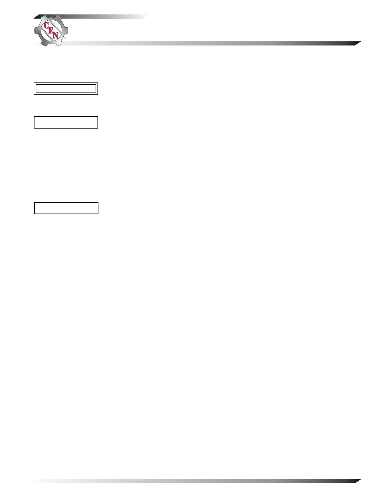
CEN N1607 and N1611
Alternator Description and Operation
N1607 500 A 28 V and N1611 570 A 28 V alternators
are internally rectified. All windings and current-transmitting components are non-moving, so there are no
brushes or slip rings to wear out. Energize switch
activates regulator. Field coil is then energized.
Alternator output current is self-limiting and will
not exceed rated capacity of alternator.
N3215B remote-mounted regulator used with these
units:
• regulates alternator voltage so that neither Battery A
signal nor Battery B signal exceeds 30.0 volts.
• is negative temperature compensated according
to switch-selected vehicle battery type. Switch is
factory-set to position 2. Customer selects position
per application
—Position 1 for 6TAGM
—Position 2 for 6TMF
B+ connections on alternator
Both positive cables must be connected together at alternator or
isolator input when alternator is installed in vehicle and during
operation. Interconnect cable is part of vehicle cabling.
Interconnect
cable
B– connections on alternator
Both ground cables must be connected to vehicle’s common
ground. An interconnect cable is required as shown if a single
cable to vehicle common ground is used.
Figure 1 — N1607 and N1611 Alternator
Interconnect
cable
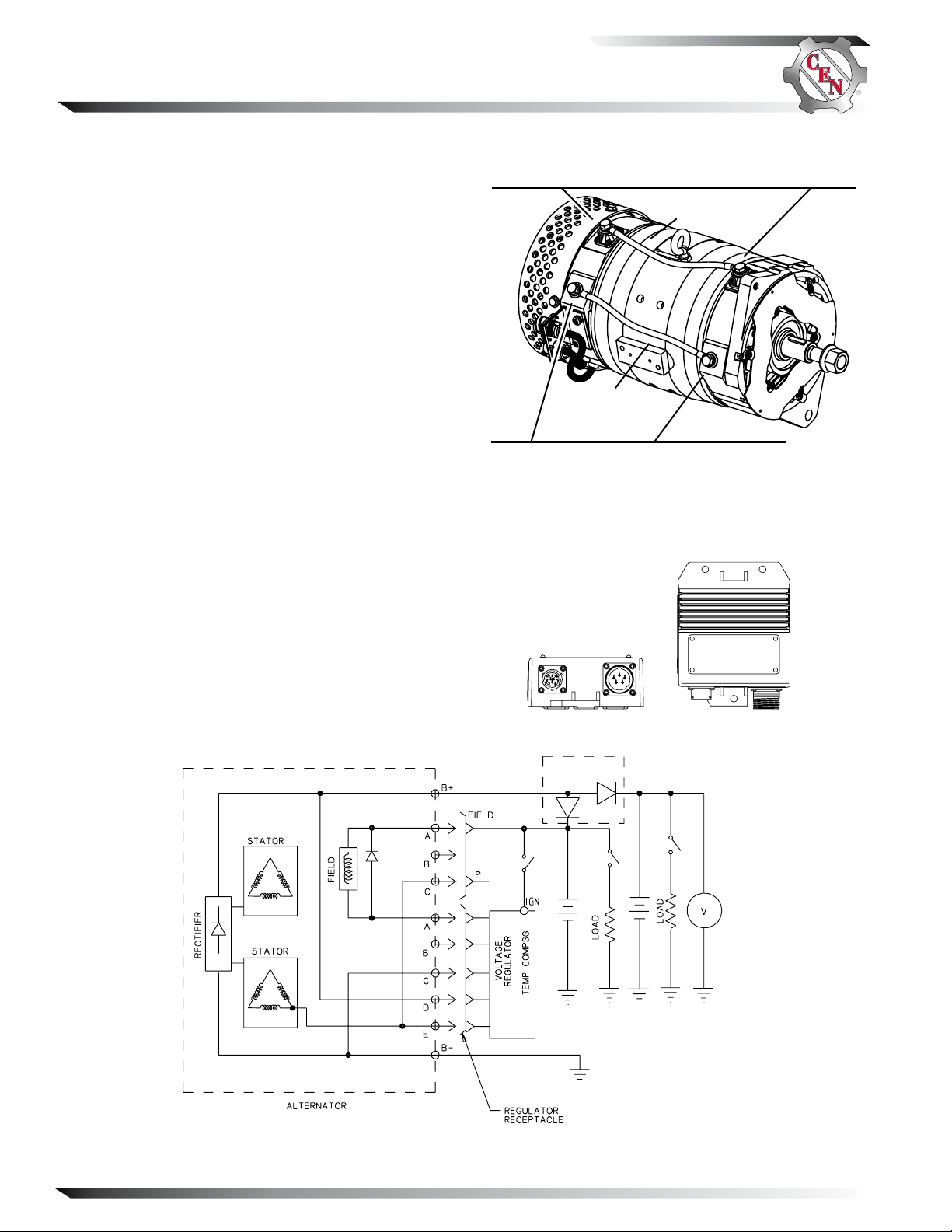
Figure 2 — N3215B Regulator Connections
BATTERY ISOLATOR
(SEE PAGE 3 FOR DETAILS)
Figure 3 — N1607 and N1611 Alternators with Regulator
Page 2
TG56B
Page 3

N2013 Battery Isolator Description
and Operation
N2013 battery isolator used with this charging system:
• allows alternator to charge two battery banks at the
same time.
• allows one battery bank to discharge without draining the other.
• is rated for 14 V or 28 V DC nominal. 600 A max.
current.
• operates optimally between -40ºC to 65ºC (-40ºF to
149ºF) ambient temperature.
• includes voltage ripple filter connected to negative
ground.
Section A: Component Description (CONT’D)
System #2 connection
Alternator connection
System #1 connection
Ground bolt
Figure 4 – N2013 Battery Isolator
TG56B
Figure 5 - Generic Wiring Schematic for Reference Only—See Vehicle Manufacturer Specications
Page 3
Page 4

Section B: Basic Troubleshooting
Tools and Equipment for Job
• Digital Multimeter (DMM)
• Ammeter (digital, inductive)
• Jumper wires
Identification Record
List the following for proper troubleshooting:
Alternator model number ________________________
Regulator model number ________________________
Setpoint listed on regulator _____________________
Battery isolator model number ___________________
Preliminary Check-out
Check symptoms in Table 1 and correct if necessary.
TABLE 1 – System Conditions
SYMPTOM ACTION
Low Voltage Output
High Voltage Output
No Voltage Output
Check: loose drive belt; low bat-
tery state of charge.
Check: current load on system
is greater than alternator
can produce.
Check: defective wiring or poor
ground path; low regu lator setpoint.
Check: defective alternator
and/or regulator.
Check: wrong regulator.
Check: high regulator setpoint.
Check: defective regulator.
Check: alternator.
Check: presence of energize
signal.
Check: battery voltage at alter-
nator output terminal.
Basic Troubleshooting
1. Inspect charging system components
Check connections at ground cables, positive
cables, and regulator harness. Repair or replace
any damaged component before troubleshooting.
2. Inspect battery isolator connections
Connections must be attached properly and
clean and tight. See Figure 4, page 3.
3. Inspect connections of vehicle batteries
Connections must be clean and tight.
4. Determine battery type, voltage and state
of charge
Batteries in each bank must be all the same type
for system operation. If batteries are discharged,
recharge or replace batteries as necessary. Electri cal system cannot be properly tested unless batter ies are charged 95% or higher. See page 1 for
details.
5. Connect meters to alternator
Connect red lead of DMM to alternator 28 V B+
terminal and black lead to alternator B– termi nal. Clamp inductive ammeter on 28 V B+ cable.
6. Operate vehicle
Observe charge voltage.
If charge voltage is above
32 volts, immediately shut
down system. Electrical
system damage may occur if
charging system is allowed
to operate at excessive
voltage. Go to Table 1 at left.
If voltage is at or below regulator setpoint, let
charging system operate for several minutes to
normalize operating temperature.
7. Observe charge volts and amps in each circuit
Charge voltage should increase and charge
amps should decrease. If charge voltage does not
increase within ten minutes, continue to next step.
8. Batteries are considered fully charged if charge
voltage is at regulator setpoint and charge amps
remain at lowest value for 10 minutes.
9. If charging system is not performing properly,
go to page 5.
CAUTION
Page 4
TG56B
Page 5

Section C: Advanced Troubleshooting
Perform on-vehicle troubleshooting
NOTICE
before attempting on-bench tests
or static tests.
Tools and Equipment for Testing
• Digital Multimeter (DMM)
• Ammeter (digital, inductive)
TABLE 2 – N3215B Regulator/Alternator Lights
on Vehicle
REG.
Off
On*
Off
On*
* If alternator light comes on within 30 seconds of regulator
light coming on, regulator has registered OVCO. If alternator
light does not come on within 30 seconds, go to Test Procedure 1.
ALT.
Off
Off
On
On
System is OK.
Go to Test Procedure 1 on page 5.
Go to Test Procedure 2 on page 5.
Go to Test Procedure 2 on page 5.
STATUS
TEST PROCEDURE 1
The following tests will determine whether regulator
and cabling is functioning. If any cabling test fails,
fix cabling, otherwise, regulator is defective.
See Figures 6 and 7.
1. First check to make sure all cabling between
vehicle and regulator is tight.
2. With engine off, at 10-pin connector on regulator
make sure there is battery voltage between pin A
and vehicle chassis ground, then pin H and
vehicle chassis ground. Then check for 10K ohms
± 4K ohms between pins C & D.
3. With engine off, check for continuity between pin
A on 5-pin connector on regulator and pin A on
5-pin connector on alternator.
4. With engine running, check for battery voltage at
pin B on 5-pin connector at regulator.
5. With engine off, check for continuity between pin
C on 5-pin connector at regulator and ground.
Then check for continuity between pin D and B+
stud on alternator.
6. With engine off, check for continuity between pin
E on 5-pin connector on regulator and the pin
that drives the instrument panel regulator
warning light on vehicle.
Connector #2
REGULATOR CONNECTOR #2
PIN CONNECTIONS
A Battery A +28V Sense
B Unused
C Temperature Sense +
D Temperature Sense –
E PGM
F PGM
G PGM
H Battery B +28V Sense
J Unused
K Unused
}
Do
Not
Use
Figure 6 — Regulator Connectors
ALTERNATOR
CONNECTOR #2
SOCKET
CONNECTIONS
A F+
B Not used
C Phase
Connector
#2
Figure 7 — Alternator Connectors (ADE)
Connector #1
REGULATOR CONNECTOR #1
PIN CONNECTIONS
A F–
B Energize
C B –
D B+
E Regulator OVCO Status
ALTERNATOR
CONNECTOR #1
SOCKET
CONNECTIONS
A F–
#1
B Not used
C B–
D B+
E Phase
Connector
TEST PROCEDURE 2
The following tests will determine whether alternator is
functioning.
During these tests, engine MUST BE running.
See Figure 7 and wiring diagram on page 2.
1. Disconnect harness at Connector #2 before start ing engine. Then, start engine. In harness plug, test
for battery voltage at socket A. If battery voltage
does not exist, vehicle wiring must be checked.
If battery voltage exists, go to Step 2.
2. All of the following tests must prove to be good:
a. Are there less than 2 ohms between socket A
in connector #2 and pin A in connector #1?
b. Does continuity exist between pin C in
connector #1 and alternator ground?
c. Using diode tester, are there 1-2 V between
pins C and D in connector #1?
d. Does continuity exist between pin D and B+
terminal on alternator?
If ALL tests are good, go to Step 3.
If ONE test is bad, alternator is defective.
3. With engine off: Connect one jumper between
socket A in connector #2 and one positive terminal
on battery pack or isolator. Connect one end of
second jumper to pin A in connector #1. Momen tarily touch the other end of the jumper to ground.
Spark will occur. Touch steel tool to alternator
shaft at drive end to detect significant magnetism.
If shaft is magnetized, regulator is defective. If
shaft is not magnetized, alternator is defective.
TG56B
Page 5
Page 6

Section C: Advanced Troubleshooting (CONT’D)
Chart 1 – No Power to System #1 or #2 with Engine Running
Before Troubleshooting, Check Batteries for Proper Charge Voltage. See Page 1.
Disconnect battery master switches.
Check for 0.1 V diode voltage drop between System 1 terminal on isolator and alternator terminal
on isolator. Then check for 0.1 V diode voltage drop between System 2 terminal on isolator and
alternator terminal on isolator.
Does the voltage drop exist at each set of tests?
Yes No
Go to page 4 to troubleshoot
alternator and regulator.
Battery isolator
is defective.
System #2 connection
Alternator connection
System #1 connection
Ground bolt
Figure 8 – N2013 Battery Isolator
If you have questions about your alternator or any of these test procedures, or if you need to locate a Factory Authorized Service Dea ler, please contact us at:
C. E. Niehoff & Co.• 2021 Lee Street • Evanston, IL 60202 USA
TEL: 800.643.4633 USA and Canada • TEL: 847.866.6030 outside USA and Canada • FAX: 847.492.1242
E-mail us at service@ CENiehoff.com
Page 6
TG56B
 Loading...