

Page 1
C.E. Niehoff & Co.
Troubleshooting Guide
for N1450 Alternators
Hazard Defi nitions
These terms are used to bring attention to presence of hazards
of various risk levels or to important information concerning
product life.
Indicates presence of hazards that
CAUTION
will or can cause minor personal
injury or property damage.
Indicates special instructions on
installation, operation or mainte-
NOTICE
nance that are important but not
related to personal injury hazards.
Table of Contents
Section A: Wiring Diagram ......................................2
Section B: Basic Troubleshooting ............................3
Section C: Advanced Troubleshooting ................ 4 – 5
Battery Conditions
Until temperatures of electrical
NOTICE
system components stabilize, these
conditions may be observed during
cold-start voltage tests.
• Maintenance/Low Maintenance Battery
— Immediately after engine starts, system volts are
lower than regulator setpoint, amps are medium.
— 3–5 minutes into charge cycle, system volts
increase, amps decrease.
— 5–10 minutes into charge cycle, system volts
increase to, or near, regulator setpoint and amps
decrease to a minimum.
— Low maintenance battery has same characteristics
with slightly longer recharge times.
• Maintenance-free Battery
— Immediately after engine starts, system volts are
lower than regulator setpoint, low charging amps.
— Once charge cycle begins, low volts and low amps
are still present.
— After alternator energizes, voltage will increase
several tenths. Amps will increase gradually, then
quickly, to medium to high amps.
— F i n a l l y , v o l t s w i l l i n c r e a s e t o s e t p o i n t a n d a m p s w i l l
decrease.
The time it takes to reach optimum voltage and amperage will vary with engine speed, load, and ambient
temperature.
• High-cycle Maintenance-free Battery
These batteries respond better than standard maintenance-free. Charge acceptance of these batteries may
display characteristics similar to maintenance batteries.
• AGM (Absorbed Glass Mat) Maintenance-free Battery
These dry-cell batteries respond better than standard
maintenance-free. If battery state of charge drops to
75% or less, batteries should be recharged to 95% or
higher separately from the engine’s charging system to
avoid damaging charging system components and to
provide best overall performance. Charge acceptance of
these batteries may display
maintenance batteries.
characteristics similar to
Battery Charge Volt and Amp Values
Volt and amp levels fluctuate depending on the battery state
of charge. If batteries are in a state of discharge—as after
extended cranking time to start the engine—system volts
will measure lower than the regulator setpoint after the
engine is restarted and system amps will measure higher.
This is a normal condition for the charging system; the
greater the battery discharge level, the lower the system
volts and the higher the system amps. The volt and amp
readings will change as batteries recover and become fully
charged: system volts will increase to regulator setpoint
and system amps will decrease to low level (depending on
other loads).
• Low Amps: Minimum or lowest charging system amp
value required to maintain battery state of charge,
obtained when testing the charging system with a fully
charged battery and no other loads applied. This value
will vary with battery type.
• Medium Amps: System amps value which can cause
the battery temperature to rise above adequate charging
temperature within 4-8 hours of charge time. To prevent battery damage, the charge amps should be reduced when battery temperature rises. Check battery
manufacturer’s recommendations for proper charge
amp rates.
• High Amps: System amps value which can cause
the battery temperature to rise above adequate charging
temperature within 2-3 hours of charge time. To prevent battery damage, the charge amps should be reduced when battery temperature rises. Check battery
manufacturer’s recommendations for proper charge
amp rates.
• Battery Voltage: Steady-state voltage value as mea-
sured with battery in open circuit with no battery load.
This value relates to battery state of charge.
• Charge Voltage: Voltage value obtained when the
charging system is operating. This value will be higher
than battery voltage and must never exceed the regulator voltage setpoint.
• B+ Voltage: Voltage value obtained when measuring
voltage at battery positive terminal or alternator B+
terminal.
• Surface Charge: Higher than normal battery voltage
occurring when the battery is disconnected from
battery charger. The surface charge must be removed
to determine true battery voltage and state of charge.
• Significant Magnetism: Change in strength or inten-
sity of a magnetic field present in alternator rotor shaft
when the field coil is energized. The magnetic field
strength when the field coil is energized should feel
stronger than when the field is not energized.
• Voltage Droop or Sag: Normal condition occurring
when the load demand on alternator is greater than
rated alternator output at given rotor shaft RPM.
TG57B
Page 1
Page 2
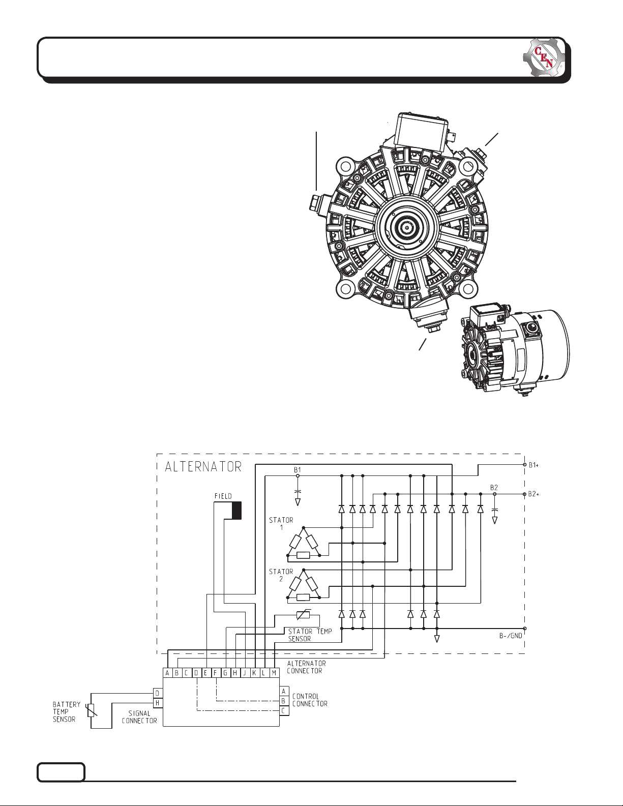
Section A: Wiring Diagram
CEN N1450 Alternator
Description and Operation
N1450 28 V (400 A) alternator is internally rectified.
There are no brushes or slip rings to wear out.
Energize switch activates regulator. Exciter stator
is then energized.
After engine is running, the regulator receives energize
signal. Regulator monitors alternator rotation and provides field current only when it detects alternator shaft
rotating at suitable speed.
N3227 or N3250 regulator used with some units:
• is negative temperature compensated.
• maintains alternator output voltage at regulated
settings as vehicle electrical loads are switched
on and off.
• provides overvoltage cutout (OVCO). Regulator will
trip OVCO when system voltage rises above 32 V for
longer than 3 seconds. OVCO feature detects high
voltage and reacts by disconnecting field and turning
off alternator. Restarting engine or waiting until
system voltage drops below 24 V will reset OVCO
circuit.
B– terminal
B+2 secondary
(low load)
output
terminal
B+1 primary
(high load)
output
terminal.
Battery must
be connected
to this terminal
for unit to be
energized.
Figure 1 — N1450 Alternator Terminals
Page 2
Figure 2 — N1450 Wiring Diagram
TG57B
Page 3

Section B: Basic Troubleshooting
Tools and Equipment for Job
• Digital Multimeter (DMM)
• Ammeter (digital, inductive)
• Jumper wires
Identifi cation Record
List the following for proper troubleshooting:
Alternator model number _________________________
Regulator model number ________________________
Setpoint listed on regulator ______________________
Preliminary Check-out
Check symptoms in Table 1 and correct if necessary.
TABLE 1 – System Conditions
SYMPTOM
Low Voltage Output
High Voltage Output
No Output
Check: low battery state of
charge.
Check: current load on system
is greater than alternator
can produce.
Check: defective wiring or poor
ground path; low regu lator setpoint.
Check: defective alternator or
regulator.
Check: wrong regulator.
Check: high regulator setpoint.
Check: defective regulator.
Check: alternator.
Check: battery voltage at alter-
nator output terminals.
Check: defective alternator
or regulator.
ACTION
4. Connect meters to alternator
Connect red lead of DMM to B+ terminal(s) and
black lead to alternator B– terminal. Clamp induc tive ammeter(s) on B+ cable(s).
5. Operate vehicle
Observe charge voltage at batteries with engine
running (nom. 27-28 V).
If charge voltage is above
32 V, immediately shut
down system. Electrical
system damage may occur if
charging system is allowed
to operate at excessive
voltage. Go to Table 1.
If voltage is at or below regulator setpoint, let
charging system operate for several minutes to
normalize operating temperature.
6. Observe charge volts and amps
Charge voltage should increase and charge amps
should decrease. If charge voltage does not in crease within ten minutes, continue to next step.
7. Batteries are considered fully charged if charge
voltage is at regulator setpoint and charge amps
remain at lowest value for 10 minutes.
8. If charging system is not performing properly,
go to Chart 1, page 4.
9. Check OVCO circuit
Shut down vehicle and restart engine. If alternator
functions normally after restart, a “no output
condition” was a normal response of voltage
regulator to “high voltage” condition. Inspect
condition of electrical system, including loose
battery cables, both positive and negative. If battery
disconnects from system, it could cause “high
voltage” condition in electrical system, causing
OVCO circuit to trip.
If you have reset alternator once, and electrical
system returns to normal charge voltage condition,
there may have been a one time, high voltage spike,
causing OVCO circuit to trip.
If OVCO circuit repeats cutout a second time in
short succession, try third restart. If OVCO
circuit repeats cutout, go to Chart 2, page 5.
CAUTION
Basic Troubleshooting
1. Inspect charging system components for damage
Check connections at B– cable, B+ cables, and
alternator-to-regulator harness. Repair or replace
any damaged component before troubleshooting.
2. Inspect all vehicle battery connections
Connections must be clean and tight.
3. Determine battery voltage and state of charge
If batteries are discharged, recharge or replace
batteries as necessary. Electrical system cannot
be properly tested unless batteries are charged
95% or higher. In addition, open circuit voltages
must be within ± 0.2 V.
TG57B
Page 3
Page 4
Section C: Advanced Troubleshooting
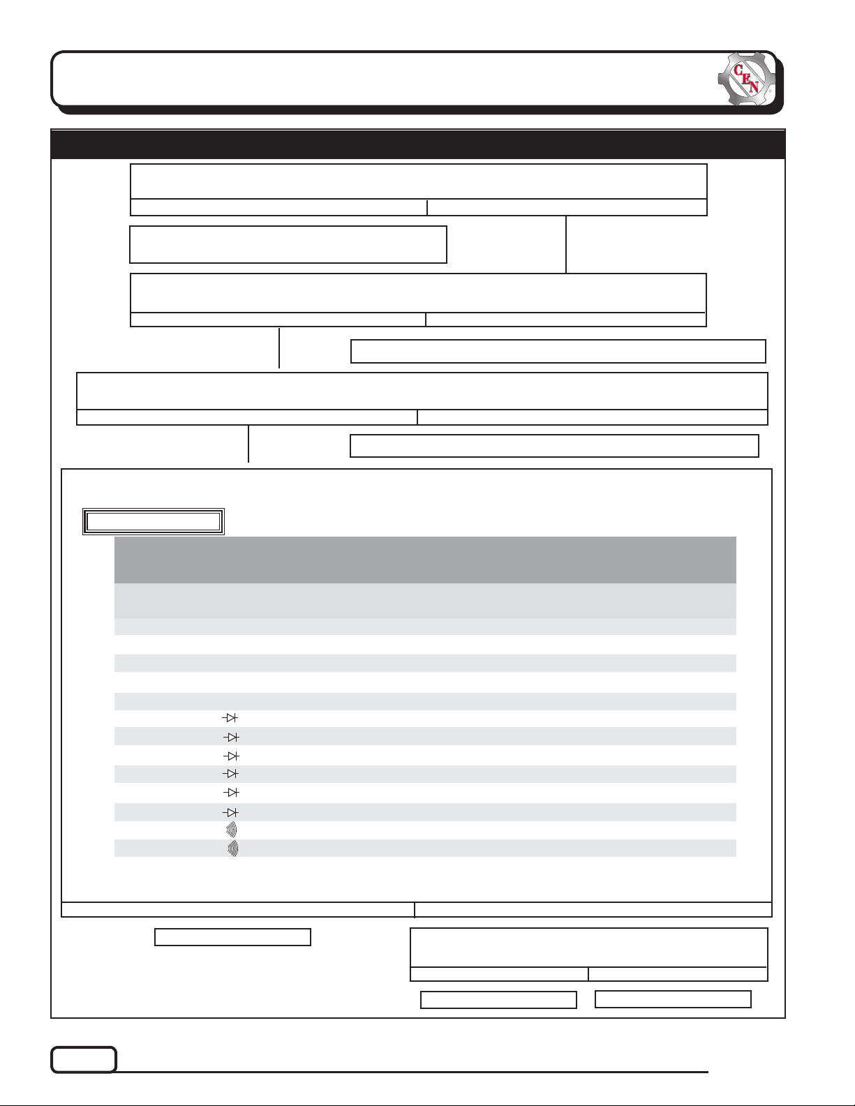
Chart 1 – No Alternator Output – Test Charging Circuit
Shut down vehicle and restart engine or wait until system voltage drops below 28 V. Does alternator function normally after restart?
Yes
No
Regulator responded to overvoltage condition.
Go to Chart 2 on page 5 to troubleshoot OVCO.
Shut off engine. With key off, engine off: Test for battery voltage at alternator B+1 terminal
connected to battery. Does battery voltage exist?
Yes
No
Repair vehicle battery circuit wiring as necessary. Continue test.
Disconnect 3-socket harness plug from regulator. With key on, engine running: Test for battery voltage between
pin B in 3-pin connector on regulator and alternator B– terminal. Does battery voltage exist?
Yes No
Repair vehicle ignition circuit wiring as necessary. Continue test.
MASTER BATTERY SWITCH OFF, KEY OFF, ENGINE OFF: Reconnect 3-socket harness to regulator. Disconnect alternator-to-regulator harness at regulator. Follow static tests in Table 2. Has any test result failed?
Alternator should not be powered during static tests. Connections required during
WARNING
testing can cause shorts and damage alternator.
TABLE 2 Pin-to-Pin Tests (See Figure 3)
DISCONNECT ALTERNATOR-TO-REGULATOR WIRING HARNESS AT REGULATOR.
TESTS MUST BE PERFORMED AT ROOM TEMPERATURE.
1
2
3
4
5
6
7
8
9
10
11
12
13
METER SCALE
& SYMBOL
Ohms Ω
Ohms Ω
Ohms Ω
Ohms Ω
Ohms Ω
Diode Test
Diode Test
Diode Test
Diode Test
Diode Test
Diode Test
Continuity
Continuity
TEST
NO.
* Meter will show OL when capacitors are fully charged and readings stabilize.
** Meter will show voltage drop of all diodes in parallel when capacitors are fully charged and readings stabilize.
NOTE 1: If PC board is present , <0.7 volt (flow). If not present, <0.3 volt (f low).
METER (+) LEAD
CONNECTION
Pin J
Pin M
Pin L
Pin E
Pin G
Alt. B– Terminal
Alt. B– Terminal
Alt. B+ 1 Termina l
Alt. B– Terminal
Alt. B+ 2 Termina l
Alt. B– Terminal
Pin A
Alt. B+ 1 Termina l
METER (–) LEAD
CONNECTION
Pin K
Alt. B– Terminal
Alt. B+ 1 Termina l
Alt. B+ 2 Termina l
Pin H
Pin A
Pin B
Alt. B– Terminal
Alt. B+ 1 Termina l
Alt. B– Terminal
Alt. B+ 2 Termina l
Pin B
Alt. B+ 2 Termina l
TESTED CIRCUIT
Field circuit
Ground circuit
Power circuit (B+ 1)
Power circuit (B+ 2)
Stator temp sensor
Phase circuit (P1)
Phase circuit (P2)
All diodes in parallel (B+ 1)
All diodes in parallel (B+ 1)
All diodes in parallel (B+ 2)
All diodes in parallel (B+ 2)
Stator-to-stator continuity
B+ 1 to B+ 2 continuity
Yes
Alternator is defective.
Replace regulator with known good regulator. Run engine.
Does no-output condition still exist?
Yes
Alternator is defective.
EXPECTED
READING
5–6 ohms
<1 oh m
<1 oh m
<1 oh m
90K to 120K ohms
See NOTE 1
See NOTE 1
OL*(blocking)
<0.7 volt**(flow)
OL*(blocking)
<0.7 volt**(flow)
OL (blocking)
OL (blocking)
No
No
Regulator is defective.
Page 4
TG57B
Page 5

Section C: Advanced Troubleshooting (CONT’D)
Chart 2 – No Alternator Output – Test OVCO Circuit
Unplug alternator-to-regulator harness from regulator. Connect red lead from DMM to pin J in plug.
Connect black lead to pin K in plug. Does resistance read 5-6 ohms?
Yes
No
Alternator is defective.
With red lead from DMM connected to pin K in plug, connect black lead to B– terminal. Does
resistance read OL (out of limits)?
Yes
Replace existing regulator with known good regulator.
Run engine. Does OVCO trip?
Yes
Alternator is defective.
ALTERNATOR CONNECTOR
A AC 1 G T+ 1
B AC 2 H T– 1
C Not used J F+
D Not used K F–
E B+ 2 L B+ 1
F Not used M B–
Original regulator is
defective.
PIN CONNECTIONS
No
Alternator is defective.
B– terminal
No
Figure 3 – Alternator-to-Regulator
Harness Plug
B+ 1 primary
(high load)
output terminal.
Battery must be
connected to this
terminal for unit
to be energized.
B+ 2
secondary
(low load) output
terminal
If you have quest ions about your a lternator or a ny of these test procedures, or if you need to locate a Factory Authorized Serv ice Dea ler, please contact us at:
C. E. Niehoff & Co.• 2021 Lee Street • Evanston, IL 60202 USA
TEL: 800.643.4633 USA and Canada • TEL: 847.866.6030 outside USA and Canada • FAX: 847.492.1242
E-mail us at service@CENiehoff.com
TG57B
Page 5
 Loading...