

Page 1
N1387 Series Troubleshooting Guide
for N1387-1 Alternators
Hazard Definitions
These terms are used to bring attention to presence of hazards
of various risk levels or to important information concerning
product life.
WARNING
injury, death or substantial property damage if ignored.
CAUTION
injury or property damage if ignored.
NOTICE
nance that are important but not related to personal injury
hazards.
Indicates the presence of hazards
that can cause severe personal
Indicates presence of hazards that
will or can cause minor personal
Indicates special instructions on
installation, operation or mainte-
Table of Contents
Section 1: Component Description .............................. 2
Section 1: Start-up/Shutdown Procedures................... 2
Section 2: Wiring .........................................................3
Section 3: CAN/J1939 Diagnostics .............................. 4
Section 4: Basic Troubleshooting ................................ 5
Section 5: Advanced Troubleshooting ...................... 6-9
Section 6: Troubleshooting the EPM ................... 10-12
Battery Conditions
NOTICE
• Maintenance or low maintenance battery:
— Immediately after engine starts, system volts are
lower than regulator setpoint with medium amps.
— 3-5 Minutes into charge cycle, system volts are
higher and amps are dropping.
— 5-10 Minutes into charge cycle, system volts are
at, or nearly at, regulator setpoint and amps are
reduced to a minimum.
— Low maintenance battery has same characteris-
tics with slightly longer recharge times.
• Maintenance-free battery:
— Immediately after engine start, system volts
are lower than regulator setpoint with low
charging amps.
— 15-30 minutes into charge cycle, volts and amps
are still low.
— 15-30 minutes into charge cycle, volts increase
several tenths. Amps increase gradually, then
quickly, to medium to high amps.
— 20-35 minutes into charge cycle, volts increase
to setpoint and amps decrease.
• High-cycle maintenance-free battery:
— These batteries respond better than standard
maintenance-free. Charge acceptance of these
batteries may display characteristics similar to
maintenance batteries.
Until temperatures of electrical
system components stabilize, these
conditions may be observed during
cold start voltage tests.
Charge Volt and Amp Values
The volt and amp levels are a function of the battery
state of charge. If batteries are in a state of discharge,
as after extended cranking time to start the engine, the
system volts, when measured after the engine is started
will be lower than the regulator setpoint and the system
amps will be high. This is a normal condition for the
charging system. The measured values of system volts
and amps will depend on the level of battery discharge.
In other words, the greater the battery discharge level,
the lower the system volts and higher the system amps
will be. The volt and amp readings will change, system
volts reading will increase up to regulator setpoint and
the system amps will decrease to low level (depending
on other loads) as the batteries recover and become
fully charged.
• Low Amps: A minimum or lowest charging system
amp value required to maintain battery state of
charge, obtained when testing the charging system
with a fully charged battery and no other loads
applied. This value will vary with battery type.
• Medium Amps: A system amps value which can
cause the battery temperature to rise above the
adequate charging temperature within 4-8 hours of
charge time. To prevent battery damage, the charge
amps should be reduced when battery temperature
rises. Check battery manufacturer’s recommendations for proper rates of charge amps.
• High Amps: A system amps value which can cause
the battery temperature to rise above adequate
charging temperature within 2-3 hours. To prevent
battery damage, the charge amps should be reduced
when the battery temperature rises. Check battery
manufacturer’s recommendations for proper rates
of charge amps.
• Battery Voltage: Steady-state voltage value as
measured with battery in open circuit with no
battery load. This value relates to battery state of
charge.
• Charge Voltage: A voltage value obtained when the
charging system is operating. This value will be
higher than battery voltage and must never exceed
the regulator voltage setpoint.
• B+ Voltage: A voltage value obtained when measur-
ing voltage at battery positive terminal or alternator
B+ terminal.
• Surface Charge: A higher than normal battery
voltage occurring when the battery is removed from
a battery charger. The surface charge must be
removed to determine true battery voltage and state
of charge.
• Significant Magnetism: A change in the strength or
intensity of a magnetic field present in the alternator
rotor shaft when the field coil is energized. The
magnetic field strength when the field coil is energized should feel stronger than when the field is not
energized.
• Voltage Droop or Sag: A normal condition which
occurs when the load demand on the alternator is
greater than rated alternator output at given rotor
shaft RPM.
TG0019A
Page 1
Page 2
Section 1: Component Description and Operation
CEN N1387-1 Dual Voltage Alternator Description and Operation
N1387-1 28 V 210 A alternator with optional 28 V/14
V (50 A maximum on 14 V) is internally rectified. All
windings and current-transmitting components are
non-moving, so there are no brushes or slip rings to
wear out.
After engine is running, N3225 regulator receives
energize signal. Regulator monitors alternator
rotation and provides field current only when it
detects alernator shaft rotating at suitable speed.
After regulator detects alternator rotation, it gradually applies field current, preventing an abrupt
mechanical load on accessory drive system. The soft
start may take up to 20 seconds.
N3225 regulator used with these units also
• is negative temperature compensated. Setpoints
are 28.0 ± 0.2 V and 14.0 ± 0.2 V at 75° F.
• provides overvoltage cutout (OVCO). Regulator
will trip OVCO when system voltage rises above
32 V in a 28 V system (16 V in a 14 V system) for
longer than 2 seconds. OVCO feature detects high
voltage and reacts by signaling relay in F– alternator circuit to open, turning off alternator. Restarting engine resets OVCO circuit. If vehicle is run in
OVCO mode OVCO will automatically reset when
system voltage drops to 22 V (11 V on 14 V side).
Regulator regains control of alternator below
output voltage.
• maintains alternator output voltage at regulated
settings as vehicle electrical loads are switched
on and off.
• can be used in single or dual voltage with this
alternator.
— Allows single-voltage operation (28 V only).
14 V is not available as a single voltage application.
— Provides optional 28 V/14 V output only from
the regulator when phase cable from alternator is connected to regulator.
• works with the EPM to provide dual voltage
output during batteryless operation. When
operating in batteryless mode, the system will
have higher ripple. LEDs might change color
more rapidly depending on loads.
EPM Electric Power Manager used with these units
• is rated for continuous current at 200 A on 28 V
side. The 14 V side is rated for continuous
current at 100 A.
• manually connects batteries after battery-connect
button on vehicle is pressed.
• automatically disconnects batteries from vehicle
loads 3 minutes after engine shuts down.
• provides 28 V auxillary output power for up to
four 20 A channels and 14 V auxillary output
power for one 20 A channel, protected by an
internal, resettable, electronic circuit breaker.
• keeps batteries connected to system when emergency flashers are used.
Normal Start-Up Procedure
1. Press the vehicle battery-connect button to connect
batteries.
2. Turn START-RUN switch to RUN.
3. Wait until glow plug light goes off.
4. Turn START-RUN switch to START and crank
engine.
5. Return switch to RUN when engine starts.
6. If engine fails to crank, turn START-RUN switch to
OFF, repeat steps 1-5 above.
7. If engine still fails to start, the EPM could be
damaged.
WARNING
a. Remove cables from “Load” side of EPM and
temporarily attach to “Battery” side of EPM.
b. Follow steps 2-5 above.
Do not leave vehicle cabling
connected as described in steps 7ab. Diagnostic and repair must be
performed as soon as possible.
Emergency Start-Up Procedure
WARNING
1. Connect slave vehicle Nato connector to vehicle.
2. Follow steps 2-5 above.
3. Disconnect slave NATO connector after engine is
running.
This procedure will bypass EPM and
batteries in system. Use this
procedure ONLY when vehicle must
be removed immediately from
location in an EMERGENCY.
Shutdown Procedure
1. Place gear shift in park or neutral and set parking
brake.
2. Turn start-run switch to OFF to stop engine.
3. Batteries will be disconnected from vehicle in 3
min. unless emergency flashers are on, then
batteries will stay connected until flashers are
turned off or battery is discharged.
Page 2
TG0019A
Page 3
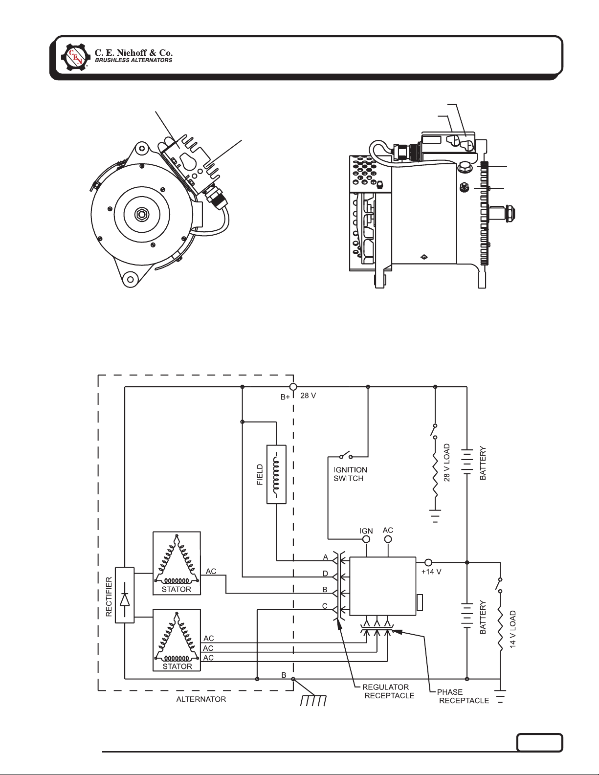
Section 2: Wiring
14 V B+ terminal
IGN terminal
Regulator
AC terminal
diagnostic
LEDs
14 V
TT
T
TT
TT
TT
T
28V
14 V
Figure 1 — N1387-1 Alternator and N3225 Regulator Terminals
TT
T
TT
TT
T
IGN
TT
T
TT
TT
T
TT
TT
28 V B+
terminal
B–
AC
terminal
TG0019A
N3225
REGULATOR
J1939
CONN
Figure 2 — N1387-1 Alternator with N3225 Regulator
Page 3
Page 4
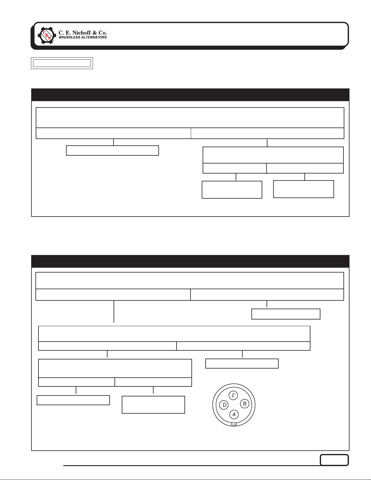
Section 3: CAN/J1939 Diagnostics
CAN/J1939 Interface
DESCRIPTION AND OPERATION
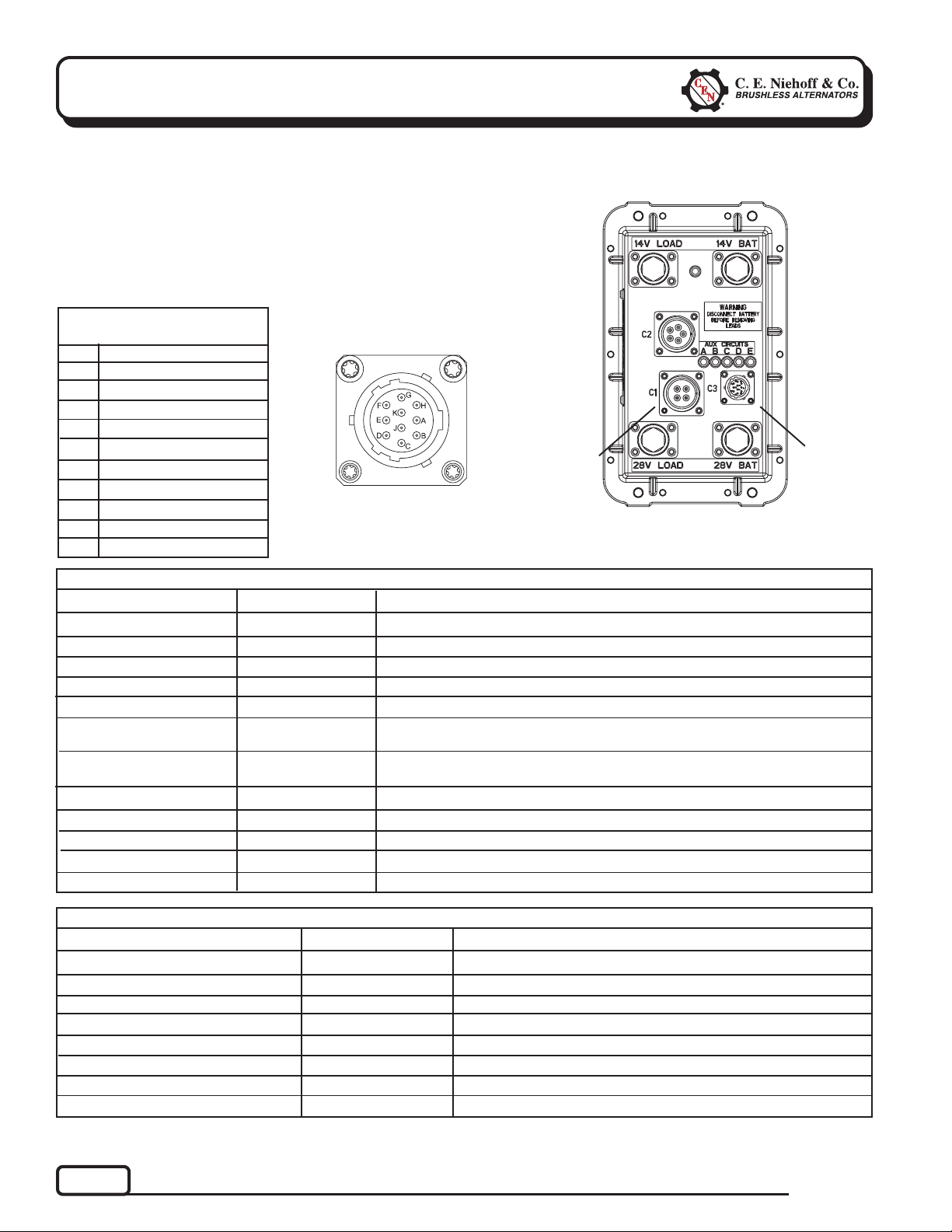
The EPM and the CEN N3225 digital regulator are compatible with the
SAE J1939 communications standard for vehicle networking.
CEN uses MIL-STD connector MS3112E12-10P to interface between the
EPM/N3225 and the DPA adapter used to monitor the broadcast
messages on the CAN bus line. The readouts of these messages are
shown in Table 2 for the EPM and Table 3 for the regulator.
TABLE 1 – J1939 Connector
Circuit Identification
Pin
A
B
C
D
E
F
G
H
J
K
Identification
CAN High
CAN Low
CAN Shield
Ground
Restricted use
Restricted use
Restricted use
unused
unused
+28V power
Figure 3 – J1939
Connector Pins
T
TT
TT
EPM
Connector
to N3225
Regulator
Figure 4 – EPM Electric Power Manager
T
TT
TT
J1939
Connector
Under Cap
TABLE 2 – EPM/J1939 Readout Diagnostics (With Engine Running)
EPM Readout
Load Voltage 28 V System
Load Voltage 14 V System
Alternator Speed
Battery Voltage 28 V System
Battery Voltage 14 V System
EPM Temperature
Charging and Discharging
Current of 28 V Battery
Batt Charging 28 V LED
Batt Charging 14 V LED
Main Switches On
Cranking Detected
Emergency Flasher Detected
Expected Reading
27–29 V
13.5–14.5 V
1200 to 6000 RPM
27–29 V
13.5–14.5 V
–50ºF (–46ºC) to
200ºF (93ºC)
10 A (varies according
to battery condition)
TABLE 3 – N3225 Regulator/J1939 Readout Diagnostics
Regulator Readout
Alternator Output Voltage 28 V System
Alternator Output Voltage 14 V System
Alternator Speed
Alternator Temperature
Battery Voltage 28 V System
Battery Voltage 14 V System
Alternator Output Capacity
Charging System Status
See Chart 1, page 7.
See Chart 2, page 8.
Check drive belt and charging system connection.
See Chart 1, page 7.
See Chart 2, page 8.
Check connections to EPM.
Observe current charges with battery and ignition on and then off.
OK
OK
OK
OK
OK
See Chart 1, page 7.
See Chart 2, page 8.
Verify “Battery Connect” indicator is lit AMBER.
See Chart 5, page 11.
Check bulbs on flashers or ICC to battery.
Expected Reading
27–29 V
13.5–14.5 V
1200 to 6000 RPM
Less than 260º F/127ºC
27–29 V
13.5–14.5 V
0–100%
OK
Action If Expected Reading Not Achieved
Action If Expected Reading Not Achieved
See Chart 1, page 7.
See Chart 2, page 8.
Check drive belt and chg system connection.
Decrease load on alternator. See Chart 4, page 9.
See Chart 1, page 7.
See Chart 2, page 8.
Varies with load.
See Chart 1, page 7, or Chart 2, page 8.
Page 4
TG0019A
Page 5

Section 4: Basic Troubleshooting
A. Tools and Equipment for Job
• Digital Multimeter (DMM)
• Ammeter (digital, inductive)
• Jumper wires
If no tools are available, monitor LED code.
B. Identification Record
List the following for proper troubleshooting:
Alternator model number ____________________
❏
Regulator model number _____________________
❏
Setpoint listed on regulator ___________________
❏
EPM model number __________________________
❏
TABLE 4 – System Conditions
SYMPTOM
Low Voltage Output
High Voltage Output
No Voltage Output
No 14 V Output
Check: loose drive belt; low
battery state of charge.
Check: current load on system
is greater than alternator
can produce.
Check: defective wiring or poor
ground path.
Check: defective alternator
and/or regulator.
Check: defective regulator.
Check: alternator.
Check: presence of energize
signal to IGN terminal on
regulator.
Check: battery voltage at alter-
nator output terminal.
Check: defective alternator
and/or regulator.
Check:defective regulator.
Check:cable from 14 V regulator
terminal to battery.
ACTION
C. Basic Troubleshooting
1. Inspect charging system components
Check connections at ground cables, positive
cables, and regulator harness. Repair or replace
any damaged component before troubleshooting.
2. Inspect EPM connections
Connections must be in proper sequence and
clean and tight. See Figure 9, page 10.
3. Inspect connections of vehicle batteries
Connections must be clean and tight.
4. Determine battery type, voltage, and state
of charge
Batteries must be all the same type for system
operation. If batteries are discharged, recharge
or replace batteries as necessary. Electrical
system cannot be properly tested unless batteries are charged 95% or higher. See page 1 for
details.
5. Connect meters to alternator
Connect red lead of DMM to alternator 28 V B+
terminal and black lead to alternator B– terminal. Clamp inductive ammeter on 28 V B+
cable.
6. Operate vehicle
Follow start-up procedure on Page 2. Observe
charge voltage.
CAUTION
or 16 V for 14 V system, immediately shut down system.
Electrical system damage may occur if charging system
is allowed to operate at excessive voltage. Go to page 9.
If voltage is at or below regulator setpoint, let
charging system operate for several minutes to
normalize operating temperature.
7. Observe charge volts and amps in each circuit
Charge voltage should increase and charge amps
should decrease. If charge voltage does not increase within ten minutes, continue to next step.
8. Batteries are considered fully charged if charge
voltage is at regulator setpoint and charge amps
remain at lowest value for 10 minutes.
9. If charging system is not performing properly,
go to Chart 1, page 7.
If charge voltage is above
33 volts for 28 V system
TG0019A
Page 5
Page 6

Section 5: Advanced Troubleshooting
N3225 Regulator
DESCRIPTION AND OPERATION
N3225 Regulator with OVCO is attached directly to
the outside of the alternator. Regulator setpoint has
negative temperature compensation. At 75ºF, the
setting is 28.2 V for 28 V system and 14.1 V for 14 V
system.
Main diagnostic feature of N3225 regulator consists
of two bicolored (amber, green) LEDs located on the
side of the regulator. One LED indicates 28 V system
performance, the other LED indicates 14 V system
performance. The two LEDs work independently of
each other. See Table 5 for diagnostic features and
LED explanations.
OVCO (overvoltage cutout) will trip at any of the
following conditions:
• 14 V side trips at voltage higher than regulator
setpoint that exists longer than 2 seconds of
reading voltage above 16 V. OVCO feature detects
overvoltage and reacts by signaling relay in F–
alternator circuit to open. This turns off alternator (14 V LED is flashing AMBER /28 V LED is
off). OVCO circuit will reset by restarting engine
(regulator regains control ofalternator output
voltage and resets OVCO).
• 28 V side trips at voltage higher than regulator
setpoint that exists longer than 2 seconds of
reading voltage above 32 V. OVCO feature detects
overvoltage and reacts by signaling relay in F–
alternator circuit to open. This turns off alternator (28 V LED is flashing AMBER / 14 V LED is
off). OVCO circuit will reset by restarting engine
(regulator regains control of alternator output
voltage and resets OVCO).
TROUBLESHOOTING
Shut down vehicle and restart engine per start-up
procedure on page 2. If alternator functions normally
after restart, a “no output condition” was normal
response of voltage regulator to overvoltage condition. Inspect condition of electrical system.
If you have reset alternator once, and electrical
system returns to normal charge voltage condition,
there may have been a one time, overvoltage spike
that caused OVCO circuit to trip.
If OVCO circuit repeats cutout a second time in short
succession and shuts off alternator F– circuit, try
third restart. If OVCO circuit repeats cutout a third
time, check color of LEDs while engine is running.
28 V LED flashing AMBER / 14 V LED off—go to
Chart 4, page 9.
14 V LED flashing AMBER /28 V LED off—go to
Chart 3, page 9.
Page 6
TABLE 5 – N3225 Regulator LEDs Diagnostics
N3225 LEDs COLOR N3225 STATUS
Off (Clear)
Flashing AMBER
(either 28 V or 14 V)
AMBER
(either 28 V or 14 V
with the other LED
off)
GREEN
(both flashing once
every 5 sec.)
Steady AMBER
GREEN
Regulator is not energized. Measure IGN terminal voltage.
If voltage is above 21 V, regulator is defective.
Respective system voltage is reading high voltage.
Alternator is shut down and is not producing power for either
voltage. 28 V side trips after 2 seconds of reading voltage
above 32 V. 14 V side trips after 2 seconds of reading voltage
above 16 V. Regulator remains in this mode until reset by
restarting engine or if system voltage drops below 22 V or 11
V, respectively. See Chart 3 on page 9 of Troubleshooting
Guide for 28V systems, Chart 4 for 14 V systems.
Regulator is energized, but waiting for AC signal from alternator.
Respective system voltage is below regulated setting or is
processing soft start (20-second delay).
Normal operation (respective system voltage is at regulated setting)
TG0019A
Page 7

Section 5: Advanced Troubleshooting
Chart 1 – 28 V LED Steady AMBER – No 28V Alternator Output – Test Charging Circuit
(CONT’D)
CAUTION
Start engine. Wait 20 seconds. Is 28 V LED steady GREEN on regulator?
Regulator responded to overvoltage condition. Go to Chart 4
on page 9 to troubleshoot OVCO.
Shut off engine. With key off, engine off: Test for battery voltage at alternator 28 V B+
terminal. Does battery voltage exist?
With key on, engine running: Test for battery voltage between IGN terminal on regulator and alternator
B– terminal. Does 28 V battery voltage exist?
Troubleshooting sequences must be performed during 3-minute delay after battery-connect button on
vehicle is pressed. If main LED on EPM is not flashing GREEN, press button to reactivate system. LED on
EPM must be flashing GREEN while performing tests.
Ye s
Ye s
TT
T
TT
Ye s
TT
T
TT
Check and repair EPM wiring and battery cables as necessary.
Continue test.
Repair vehicle ignition circuit wiring as necessary.
No
TT
T
TT
TT
T
TT
No
No
TT
T
TT
TT
T
TT
With key off, engine off: Remove alternator-to-regulator 4-pin harness from regulator. Test for battery
voltage across sockets D and C in harness plug. Does 28 V battery voltage exist?
Ye s
Alternator is defective.
TT
T
Ye s
TT
T
TT
TT
Ye s
TT
T
TT
No
TT
T
Alternator is defective.
TT
No
With DMM, check resistance across field coil. Connect red lead of DMM to socket A in alternator-to-regulator
harness plug. Connect black lead to B+ terminal on alternator. Does meter show 2.0 ± 0.2 ohms?
Connect jumper wire from socket A in regulator harness plug to B– terminal on alternator.
Spark will occur. Touch steel tool to shaft to detect significant magnetism. Is shaft magnetized?
Test phase signal into regulator (AC). Set meter to diode tester:
Connect red lead of DMM to socket C of regulator harness and black
lead to socket B. Meter should show voltage drop value.
Then reverse meter lead connections. Meter should show OL (blocking).
Ye s
TT
T
Regulator is defective.
TT
No
TT
T
TT
No
TT
T
TT
Alternator is defective.
SOCKET CONNECTIONS
AF–
B Phase Signal AC
CB–
D 28 V B+
Figure 5 – Alternator-to-Regulator
4-Socket Harness Plug
TT
T
TT
TG0019A
Page 7
Page 8

Section 5: Advanced Troubleshooting
(CONT’D)
Chart 2 – 14 V LED Solid AMBER – No 14 V Alternator Output – Test Circuit
CAUTION
Troubleshooting sequences must be performed during 3-minute delay after battery-connect button on
vehicle is pressed. If main LED on EPM is not flashing GREEN, press switch to reactivate system. LED on
EPM must be flashing GREEN while performing tests.
With key off, engine off: Test for battery voltage of 14 V output terminal on regulator.
Does +14 V battery voltage exist?
Ye s
No
TT
T
TT
Check and repair EPM wiring and battery cables as necessary.
Continue test.
TT
T
TT
Set DMM to diode tester. Connect red lead of DMM to socket C of regulator harness plug and black lead to each phase pin in phase harness
plug. Meter should show voltage drop value.
Then reverse meter lead connections. Meter should show OL (blocking).
Ye s
TT
T
TT
Regulator is defective.
Alternator is defective.
No
TT
T
TT
Page 8
SOCKET
Figure 6 – Alternator-to-Regulator 4-Socket Harness
Plug
Figure 7 – Phase Connection 3-Pin Harness Plug
CONNECTIONS
AF–
B Phase Signal AC
CB–
D 28 V B+
PIN CONNECTIONS
A Phase P1
B Phase P2
C Phase P3
TG0019A
Page 9
Section 5: Advanced Troubleshooting
(CONT’D)
CAUTION
Chart 3 – 14 V LED Flashing AMBER/ 28V LED Off – No Alternator Output – Test OVCO Circuit
Unplug alternator-to-regulator 4-socket harness from regulator. At receptacle on regulator, connect red lead
from DMM to pin C. Connect black lead to B– terminal. Does resistance read OL (out of limits)?
Alternator is defective.
Troubleshooting sequences must be performed during 3-minute delay after push-button switch on vehicle is
pressed. If main LED on EPM is not flashing GREEN, press switch to reactivate system. LED on EPM must be
flashing GREEN while performing tests.
Ye s
TT
T
TT
Replace regulator with known good regulator.
Run engine. Does OVCO trip?
Ye s
TT
T
TT
Alternator
is defective.
No
TT
T
TT
Original regulator
is defective.
No
TT
T
TT
Chart 4 – 28 V LED Flashing AMBER/ 14V LED Off – No Alternator Output – Test OVCO Circuit
Unplug alternator-to-regulator 4-socket harness from regulator. Connect red lead from DMM to pin A in
plug. Connect black lead to pin D in plug. Does resistance read 2.0 ± 0.2 ohms?
Ye s
TT
T
TT
With red lead from DMM connected to pin A in plug, connect black lead to B– terminal. Does
resistance read OL (out of limits)?
Ye s
TT
T
TT
Replace existing regulator with known good regulator.
Run engine. Does OVCO trip?
Ye s
TT
T
TT
Alternator is defective.
Original regulator
is defective.
No
TT
T
TT
Alternator is defective.
Figure 8 – Alternator-to-Regulator 4-Socket Harness Plug
No
TT
T
TT
No
TT
T
TT
Alternator is defective.
SOCKET
CONNECTIONS
AF–
B Phase Signal AC
CB–
D 28 V B+
TG0019A
Page 9
Page 10

Section 6: Troubleshooting the EPM
EPM Electric Power Manager
DESCRIPTION AND OPERATION
Main diagnostic feature of the EPM is a bicolored
(amber, green) LED located on the side of the device.
The EPM manually connects and automatically
disconnects batteries after 3 minutes unless emergency flashers are on.
EPM also allows batteryless operation until vehicle is
shut off.
TABLE 6 – EPM LED Diagnostics
EPM LED COLOR
Off (Clear)
Flashing GREEN
Steady GREEN
EPM is not energized or EPM is
defective.
EPM has connected the batteries
during start-up and has prevented
automatic disconnection for 3
minutes after vehicle shuts down
when only vehicle battery-connect
button is pressed.
Normal operation (batteries are
connected to the system and
engine is running)
TABLE 7 – EPM Harness Plug
Socket Functions
Pin
Battery Ground
A
Alternator Phase In Signal
B
Energize (Active Low) Signal
C
Ignition Signal
D
Function
EPM STATUS
TABLE 8 – AUX Circuit and LED Functions
Pin
(Max. 30 A)
A
B
C
D
E
EPM LED
AUX
Circuits
Connector
EPM
Connector
Function
14 V
28 V
28 V
28 V
28 V
LED Color
Normally On
GREEN
GREEN
GREEN
GREEN
GREEN
TT
TT
T
TT
TT
T
TT
TT
T
If LED
OFF:
A short or overcurrent
may have occurred.
Check AUX load wiring
and reset EPM by
pressing Low Battery
Indicator.
Aux. Load
Diagnostic
LEDs
TT
TT
T
T
TT
TT
J1939
Connector
Under Cap
(see p. 4 for
details)
EPM
EPM
EPM
Figure 9 – EPM Electric Power Manager
N3225
N1387-1
Figure 10 – EPM System Schematic
Page 10
TG0019A
Page 11

Section 6: Troubleshooting the EPM
(CONT’D)
CAUTION
Troubleshooting sequences must be performed during 3-minute delay after battery-connect button on
vehicle is pressed. If main LED on EPM is not flashing GREEN, press switch to reactivate system. LED on
EPM must be flashing GREEN while performing tests.
Chart 5 – Engine Will Not Crank at Start-Up
Before Troubleshooting, Check Batteries for Proper Charge Voltage. See Page 1.
Turn START-RUN switch to OFF. Press vehicle battery-connect button. Check LED on EPM.
Ye s
TT
T
TT
Check for continuity across 28 V and 14 V
terminals on EPM. Does continuity exist?
Ye s
TT
T
TT
Check and repair
starter and starter
wiring as necessary.
Re-test.
No
TT
T
TT
EPM is
defective.
Is LED flashing GREEN?
Disconnect 4-socket harness at EPM. While
pressing vehicle battery-connect button, check
for continuity between socket C on EPM harness
plug and ground. Does continuity exist?
Yes
TT
T
TT
EPM is
defective.
No
TT
T
TT
Check and repair
vehicle batteryconnect button and
wiring as necessary.
Re-test.
No
TT
T
TT
Chart 6 – No Power to Aux. Loads –One or More LEDs are OFF
Before Troubleshooting, Check Batteries for Proper Charge Voltage. See Page 1.
Disconnect Aux. Load harness from EPM. Turn start-run switch to OFF.
Press vehicle battery-connect button. Is LED on EPM flashing GREEN?
Ye s
TT
T
TT
Are all five Aux diagnostic LEDs lit on EPM?
Ye s
TT
T
TT
Check and repair
load and load wiring
as necessary.
Re-test.
No
TT
T
TT
EPM is
defective.
No
TT
T
TT
EPM is
defective.
TG0019A
Page 11
Page 12

Section 6: Troubleshooting the EPM
(CONT’D)
Chart 7 – 28V Only – EPM Sequence of Operation
Vehicle battery-connect button
is pressed.
3-Minute counter in EPM starts.
Batteries are connected
Flashing GREEN
START-RUN Switch operated to start vehicle
Batteries will stay connected as long as vehicle is running
or emergency flashers are on
TT
T
TT
TT
T
TT
TT
T
TT
TT
T
TT
If emergency flashers are the
TT
TT
T
only load required, engine
does not need to be started to
keep batteries connected. After
flashers are switched on, EPM
will keep power to loads until
batteries are discharged.
TT
TT
T
TT
T
TT
TT
T
TT
3-Minute delay in EPM ends
TT
T
TT
AUX LEDs Steady GREEN
AUX Current available
TT
T
TT
Normal operation
TT
T
TT
Shut down vehicle
TT
T
TT
Flashing GREEN
TT
T
TT
3-Minute Delay
TT
T
TT
3-Minute Delay Ends and EPM disconnects batteries
TT
T
TT
EPM and AUX Diagnostic LEDs OFF.
AUX Channels still available.
TT
TT
T
If you have questions about your alternator or any of these test procedures, or if you need to locate a Factory Authorized Service Distributor, please contact us at:
TEL: 800.643.4633 USA and Canada • TEL: 847.866.6030 outside USA and Canada • FAX: 847.492.1242
Page 12
C. E. Niehoff & Co.• 2021 Lee Street • Evanston, IL 60202 USA
TG0019A
 Loading...