

Page 1

N7289 Drive End Housing Assembly
.
C. E. Niehoff & Co
BRUSHLESS ALTERNATORS
for N1375 Alternators
Installation Instructions
DANGER
1. Make sure three envelopes were supplied with the new housing assembly. Each envelope contains hardware necessary to correctly assemble housing assembly onto unit.
2. On new DE housing assembly, remove and discard ALL washers and nuts affixed to
positive-negative diode pairs—SEE PAGE 2 for SPECIFIC DIODES. Do not reuse
existing hardware.
DANGER
3. Install new housing assembly on shell/stator/field coil assembly, making sure to guide
all leads through openings in housing.
This symbol is used in these instructions to indicate the presence of hazards that will cause severe personal
injury, death, or substantial property damage if ignored.
Removing hardware from other diodes will cause severe damage to equipment.
4. See pages 2 and 3 to install phase leads and fuse links on housing. Torque all new
brass nuts to 2.8–3.0 Nm/25–27 lb. in. Allow 16 hours to set, then retorque brass nuts
to 2.9–3.1 Nm/26–28 lb. in.
5. Make sure to clean all leads to be attached to terminal strip in control unit. See page 4
to attach leads to terminal strip. Torque screws to 0.9–1.1 Nm/8–10 lb. in.
6. Install lock washer and bolt provided in kit to ground terminal on housing assembly.
7. Coat diodes with fuse links with Dow Corning® 1-2577 Low VOC RTV coating or
equivalent. Do not use coating containing acetic acid (vinegar smell) on electrical
components.
II0073A
Page 1
Page 2
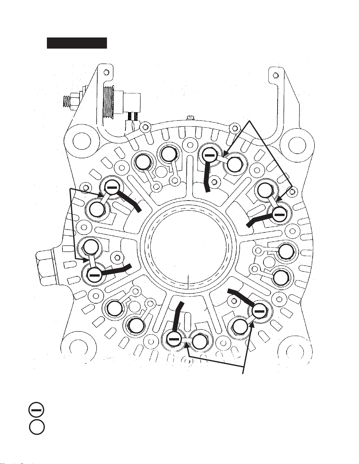
FUSE LINK INSTALLATION
Fuse links must be installed in locations shown below. Connect phase leads to negative diodes as indicated.
DANGER
Failure to install fuse links where shown below or to follow fuse link stacking order on
page 3 will cause severe damage to equipment.
FUSE LINK
(1 per pair)
+
+
FUSE LINK
(1 per pair)
+
+
P5
LEGEND:
P1
PHASE LEAD
+
+
+
P6
P1
+
P4
+
+
P3
P2
+
+
FUSE LINK
(1 per pair)
NEGATIVE DIODE
POSITIVE DIODE
+
II0073APage 2
Page 3

DANGER
FUSE LINK STACKING ORDER
Fuse links must be installed in stacking order shown below.
Failure to follow fuse link stacking order below or to install fuse links where shown on
page 2 will cause severe damage to equipment.
BRASS NUT
BELLEVILLE WASHER
9/16” FLAT WASHER
FUSE LINK
5/8” FLAT WASHER
BELLEVILLE WASHER
5/8” FLAT WASHER
TWO 3/4” dia.
GRAY INSULATORS
5/8” FLAT WASHER
5/8” WHITE INSULATOR
.25 x .3 x .9 INSULATOR
TWO 3/4” dia.
GRAY INSULATORS
+
FUSE LINK PAIR PARTS LIST
Part Qty. Req’d for Each Diode
Item Number Description POS NEG
1
N9351 3/4” dia. GRAY INSULATOR 2 2
2
N9338 5/8” FLAT WASHER 2 1
3
N9062 9/16” FLAT WASHER 1 N/A
4
N9346 BRASS NUT 1 1
5
N9347 BELLEVILLE WASHER 1 1
6
N9333 FUSE LINK 1 spans both diodes
7
N9352 .25 x .3 x .9 INSULATOR N/A 1
N9349 5/8” WHITE INSULATOR N/A 1
8
II0073A
Page 3
Page 4

TERMINAL STRIP IN CONTROL UNIT
F+
C. E. Niehoff & Co. • 2021 Lee Street • Evanston, IL 60202 Tech Services Hotline 800-643-4633
II0073APage 4
 Loading...