

Page 1
Troubleshooting Guide
for N1246-1 Alternator
Hazard Defi nitions
These terms are used to bring attention to presence of hazards
of various risk levels or to important information concerning
product life.
Indicates presence of hazards that
CAUTION
will or can cause minor personal
injury or property damage if ignored.
Indicates special instructions on
NOTICE
installation, operation or mainte nance that are important but not
related to personal injury hazards.
Table of Contents
Section 1: Wiring Diagram .......................................2
Section 2: Basic Troubleshooting .............................3
Section 3: Advanced Troubleshooting ................ 4 – 6
Battery Conditions
Until temperatures of electrical
NOTICE
system components stabilize, these
conditions may be observed during
cold start voltage tests.
• Maintenance/low maintenance battery:
— Immediately after engine starts, system volts
are lower than regulator setpoint with medium
amps.
— 3-5 minutes into charge cycle, higher system
volts and reduced amps.
— 5-10 minutes into charge cycle, system volts
are at, or nearly at, regulator setpoint, and
amps are reduced to a minimum.
— Low maintenance battery has same charac teristics with slightly longer recharge times.
• Maintenance-free battery:
— Immediately after engine start, system volts
are lower than regulator setpoint with low
charging amps.
— 15-30 minutes into charge cycle, still low volts
and low amps.
— 15-30 minutes into charge cycle, volts increase
several tenths. Amps increase gradually, then
quickly to medium to high amps.
— 20-35 minutes into charge cycle, volts increase
to setpoint and amps decrease.
• High-cycle maintenance-free battery:
— These batteries respond better than standard
maintenance-free. Charge acceptance of these
batteries may display characteristics similar
to maintenance batteries.
Charge Volt and Amp Values
The volt and amp levels are a function of the battery
state of charge. If batteries are in a state of discharge, as
after extended cranking time to start the engine, the system volts, when measured after the engine is started will
be lower than the regulator setpoint and the system
amps will be high. This is a normal condition for the
charging system. The measured values of system volts
and amps will depend on the level of battery discharge.
In other words, the greater the battery discharge level,
the lower the system volts and higher the system amps
will be. The volt and amp readings will change, system
volts reading will increase up to regulator setpoint and
the system amps will decrease to low level (depending on
other loads) as the batteries recover and become fully
charged.
• Low Amps: A minimum or lowest charging system
amp value required to maintain battery state of
charge, obtained when testing the charging system
with a fully charged battery and no other loads
applied. This value will vary with battery type.
• Medium Amps: A system amps value which can
cause the battery temperature to rise above the
adequate charging temperature within 4-8 hours of
charge time. To prevent battery damage, the charge
amps should be reduced when battery temperature
rises. Check battery manufacturer’s recommendations for proper rates of charge amps.
• High Amps: A system amps value which can cause
the battery temperature to rise above adequate
charging temperature within 2-3 hours. To prevent
battery damage the charge amps should be reduced
when the battery temperature rises. Check battery
manufacturer’s recommendations for proper rates
of charge amps.
• Battery Voltage: Steady-state voltage value as mea-
sured with battery in open circuit with no battery
load. This value relates to battery state of charge.
• Charge Voltage: A voltage value obtained when the
charging system is operating. This value will be
higher than battery voltage and must never exceed
the regulator voltage setpoint.
• B+ Volt age: A voltage value obtained when measuring voltage at battery positive terminal or alternator
B+ terminal.
• Surface Charge: A higher than normal battery voltage occurring when the battery is removed from a
battery charger. The surface charge must be removed
to determine true battery voltage and state of charge.
• Significant Magnetism: A change in the strength or
intensity of a magnetic field present in the alternator
rotor shaft when the field coil is energized. The magnetic field strength when the field coil is energized
should feel stronger than when the field is not energized.
• Voltage Droop or Sag: A normal condition which
occurs when the load demand on the alternator is
greater than rated alternator output at given rotor
shaft RPM.
TG0049A
Page 1
Page 2
Section 1: Wiring Diagram
CEN N1246-1 Dual Voltage Alternator
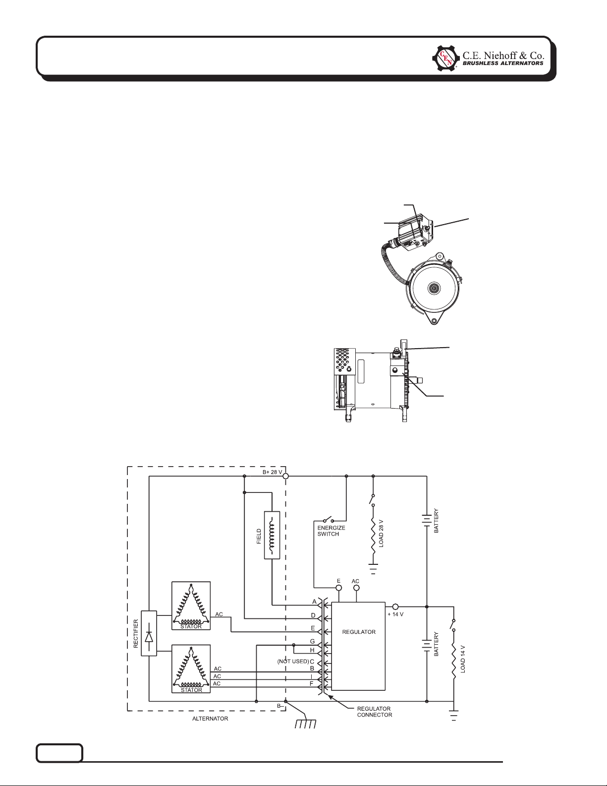
Description and Operation
N1246-1 28 V 200 A alternator with optional 28 V/
14 V (50 A maximum on 14 V) is internally rectified.
All windings and current-transmitting components
are non-moving, so there are no brushes or slip rings
to wear out.
After engine is running, remote-mounted N3231
regulator receives energize signal. Regulator
monitors alternator rotation and provides field
current only when it detects alternator shaft rotating
at suitable speed.
After regulator detects alternator rotation, it gradually
applies field current, preventing an abrupt mechanical load on accessory drive system. The soft start
may take up to 10 seconds at full electrical load.
N3231 regulator used with these units also
• is negative temperature compensated. Setpoints
are 28.0 ± 0.2 V and 14.0 ± 0.2 V at 75° F.
• provides overvoltage cutout (OVCO). Regulator will
trip OVCO when system voltage rises above 32 V
in a 28 V system (16 V in a 14 V system) for longer
than 2 seconds. OVCO feature detects high voltage
and reacts by signaling relay in F– alternator
circuit to open, turning off alternator. Restarting
engine resets OVCO circuit.
• maintains alternator output voltage at regulated
settings as vehicle electrical loads are switched
on and off.
• can be used in single or dual voltage with these
alternators.
— Allows single-voltage operation (28 V only).
14 V is not available as a single voltage appli cation with this regulator.
IGN terminal
D+ terminal
T
T
T
T
T
14 V B+ terminal
(ADE shown)
28 V B+ terminal
B– terminal
Figure 1 — N1246-1 Alternator and
N3231 Regulator Terminals
Page 2
Figure 2 — N1246-1 Alternator with N3231 Regulator Wiring Diagram
TG0049A
Page 3
Section 2: Basic Troubleshooting
A. Tools and Equipment for Job
• Digital Multimeter (DMM)
• Ammeter (digital, inductive)
• Jumper wires
B. Identifi cation Record
List the following for proper troubleshooting:
Alternator model number ______________________
T
Regulator model number _____________________
T
Setpoint listed on regulator ____________________
T
C. Preliminary Check-out
Check symptoms in Table 1 and correct if necessary.
TABLE 1 – System Conditions
SYMPTOM
Low Voltage Output
High Voltage Output
No 28 V Output
No 14 V Output
Check: loose drive belt; low bat-
tery state of charge.
Check: current load on system
is greater than alternator
can produce.
Check: defective alternator
and/or regulator.
Check: wrong regulator.
Check: defective regulator.
Check: alternator.
Check: presence of energize
signal.
Check: battery voltage at alter-
nator output terminal.
Check: defective alternator
and/or regulator.
Go to Chart 2, page 5.
ACTION
D . Basic Troubleshooting
1. Inspect charging system components
Check connections at ground cables, positive
cables, and regulator harness. Repair or replace
any damaged component before troubleshooting.
2. Inspect connections of vehicle batteries
Connections must be clean and tight.
3. Determine battery type, voltage and state
of charge
Batteries must be all the same type for system
operation. If batteries are discharged, recharge
or replace batteries as necessary. Electrical
system cannot be properly tested unless batter ies are charged 95% or higher. See page 1 for
details. Nominal battery voltage for 28 V systems
is 25.2 ± 0.2 V; for 14 V systems is 12.6 ± 0.2 V.
Less than 25 V or 12.4 V indicates no charge
condition when engine is running.
4. Connect meters to alternator
Connect red lead of DMM to alternator 28 V
B+ terminal and black lead to alternator B–
terminal. Clamp inductive ammeter on 28 V
B+ cable.
5. Operate vehicle
Observe charge voltage at batteries with engine
running (nom. 27-28 V or 13.5-14.0 V).
If charge voltage is above
32 V for 28 V system or
16 V for 14 V system,
immediately shut down
system. Electrical system
damage may occur if charg ing system is allowed to
operate at excessive volt age. Go to Table 1 at left.
If voltage is at or below regulator setpoint, let
charging system operate for several minutes to
normalize operating temperature.
6. Observe charge volts and amps in each circuit
Charge voltage should increase and charge amps
should decrease. If charge voltage does not in-
crease within ten minutes, continue to next step.
7. Batteries are considered fully charged if charge
voltage is at regulator setpoint and charge amps
remain at lowest value for 10 minutes.
8. If charging system is not performing properly,
go to Chart 1, page 4.
9. Check OVCO (overvoltage cutout) circuit
Shut down vehicle and restart engine. If the
alternator functions normally after restart, a
“no output condition” was normal response of
voltage regulator to overvoltage condition.
Inspect condition of electrical system, including
loose battery cables, both positive and negative.
If battery disconnects from system, it could
cause overvoltage condition in electrical system,
causing OVCO circuit to trip.
If you have reset alternator once, and electrical
system returns to normal charge voltage condi tion, there may have been a one-time overvoltage
spike that caused OVCO circuit to trip.
If OVCO circuit repeats cutout a second time in
short succession and shuts off alternator F–
circuit, try third restart. If OVCO circuit repeats
cutout go to Chart 3, page 6.
CAUTION
TG0049A
Page 3
Page 4

Section 3: Advanced Troubleshooting
Chart 1 – No 28V Alternator Output – Test Charging Circuit
STATIC TEST – KEY ON, ENGINE OFF
Shut down vehicle and restart engine. Does alternator function normally after restart?
Yes
No
T
Regulator responded to overvoltage condition.
Go to Chart 3 on page 6 to troubleshoot OVCO.
T
Shut off engine. With key off, engine off: Test for battery voltage at alternator 28 V B+
terminal. Does battery voltage exist?
Yes
No
T
Repair vehicle ignition circuit wiring as necessary. Continue test.
T
With key on, engine running: Test for battery voltage between IGN terminal on regulator and alternator
B– terminal. Does 28 V battery voltage exist?
Yes
T
No
T
Repair vehicle ignition circuit wiring as necessary. Continue test.
T
With key off, engine off: Disconnect alternator-to-regulator harness from regulator. Test for battery voltage
across sockets D and G in harness plug. Does 28 V battery voltage exist?
Yes
T
No
T
T
Alternator is defective.
With DMM, check resistance across field coil. Connect red lead of DMM to socket A in alternator-to-regulator
harness plug. Connect black lead to B+ terminal on alternator. Does meter show 1.8 to 2.2 ohms?
Yes
No
T
Connect jumper wire from socket A in regulator harness plug to B– terminal
on alternator. Spark will occur. Touch steel tool to shaft to detect significant
magnetism. Is shaft magnetized?
Yes
No
T
Test phase signal into regulator (AC). Set meter to diode tester:
Connect red lead of DMM to socket G of regulator harness and
black lead to socket E. Meter should show voltage drop value.
Then reverse meter lead connections. Meter should show OL
(blocking).
Yes
T
Regulator is defective.
Alternator is defective.
No
T
Alternator is defective.
T
SOCKET CONNECTIONS
A ° F–
B ° AC1
C ° Not used
D ° B+
E ° P
F ° AC2
G ° B–
H ° B–
I ° AC3
Figure 3 – Alternator-to-Regulator
Harness Plug
T
Page 4
TG0049A
Page 5

Section 3: Advanced Troubleshooting
Chart 2 – No 14 V Alternator Output – Test Circuit
Shut off engine. With key off, engine off: Test for battery voltage of 14 V output terminal
on regulator. Does +14 V battery voltage exist?
(CONT’D)
Yes
T
Set DMM to diode tester. Connect red lead of DMM
to socket G of regulator harness plug and black
lead to each phase pin (B, F, and I) in same plug.
Meter should show voltage drop value.
Then reverse meter lead connections. Meter should
show OL (blocking).
Yes
T
Regulator is defective.
Alternator is defective.
No
T
SOCKET CONNECTIONS
A ° F–
B ° AC1
C ° Not used
D ° B+
E ° P
F ° AC2
G ° B–
H ° B–
I ° AC3
No
T
Repair vehicle wiring as necessary.
TG0049A
Figure 4 – Alternator-to-Regulator Harness Plug
Page 5
Page 6

Section 3: Advanced Troubleshooting
(CONT’D)
Chart 3 – OVCO Trip – Determine 28 V or 14 V
With meter red lead on 28 V B+ at battery and black lead on chassis ground, start engine.
Watch meter dial: Does meter read charge voltage above 29 V?
Yes No
T
28 V side tripped OVCO circuit.
Go to Chart 3b.
T
14 V side tripped OVCO circuit.
Go to Chart 3a.
Chart 3a – No 14 V Alternator Output – Test OVCO Circuit
Unplug alternator-to-regulator harness from regulator. At receptacle on regulator, connect red lead from DMM
to socket G. Connect black lead to B– terminal. Does resistance read OL (out of limits)?
Yes
T
Alternator is defective.
Replace regulator with known good regulator.
No
T
Run engine. Does OVCO trip?
Yes No
T
Alternator
is defective.
Original regulator
T
is defective.
Chart 3b – No 28 V Alternator Output – Test OVCO Circuit
Unplug alternator-to-regulator harness from regulator. Connect red lead from DMM to socket A in plug.
Connect black lead to socket D in plug. Does resistance read 1.8 ± 2.2 ohms?
Yes No
T
Alternator is defective.
T
With red lead from DMM connected to socket A in plug, connect black lead to B– terminal. Does
resistance read OL (out of limits)?
Yes
T
Replace existing regulator with known good regulator.
Run engine. Does OVCO trip?
Yes
T
Alternator is defective.
Original regulator
No
T
is defective.
Alternator is defective.
Figure 5 – Alternator-to-Regulator Harness Plug
No
T
SOCKET CONNECTIONS
A ° F–
B ° AC1
C ° Not used
D ° B+
E ° P
F ° AC2
G ° B–
H ° B–
I ° AC3
Page 6
TG0049A
Page 7

Notes
TG0049A
Page 7
Page 8

Notes
If you have questions about your alternator or a ny of these test procedures, or if you need to locate a Factory Aut horized Service Dealer, please contact us at:
TEL: 800.643.4633 USA and Canada • TEL: 847.866.6030 outside USA and Canada • FAX: 847.492.1242
Page 8
C. E. Niehoff & Co.• 2021 Lee Street • Evanston, IL 60202 USA
support@CENiehoff.com
www.CENiehoff.com
TG0049A
 Loading...