

Page 1
N1233 Series Troubleshooting Guide
for N1233-2 Alternator
Hazard Definitions
These terms are used to bring attention to presence of hazards
of various risk levels or to important information concerning
product life.
CAUTION
NOTICE
Indicates presence of hazards that
will or can cause minor personal
injury or property damage.
Indicates special instructions on
installation, operation or maintenance that are important but not
related to personal injury hazards.
Table of Contents
Section 1: Wiring Diagram...................................... 2
Section 2: Basic Troubleshooting ........................... 3
Section 3: Advanced Troubleshooting............... 4 – 5
Battery Conditions
NOTICE
conditions may be observed during cold start voltage tests.
• Maintenance/low maintenance battery:
— Immediately after engine starts, system volts are
lower than regulator setpoint with medium amps.
— 3-5 minutes into charge cycle, higher system volts
and reduced amps.
— 5-10 minutes into charge cycle, system volts are
at, or nearly at, regulator setpoint, and amps are
reduced to a minimum.
— Low maintenance battery has same characteris-
tics with slightly longer recharge times.
Until temperatures of electrical
system components stabilize, these
volts and amps will depend on the level of battery discharge. In other words, the greater the battery discharge
level the lower the system volts and higher the system
amps will be. The volt and amp readings will change,
system volts reading will increase up to regulator set
point and the system amps will decrease to low level
(depending on other loads) as the batteries recover and
become fully charged.
• Low Amps: A minimum or lowest charging system
amp value required to maintain battery state of
charge, obtained when testing the charging system
with a fully charged battery and no other loads
applied. This value will vary with battery type.
• Medium Amps: A system amps value which can
cause the battery temperature to rise above the
adequate charging temperature within 4-8 hours of
charge time. To prevent battery damage the charge
amps should be reduced when battery temperature
rises. Check battery manufacturer’s recommendations for proper rates of charge amps.
• High Amps: A system amps value which can cause
the battery temperature to rise above adequate
charging temperature within 2-3 hours. To prevent
battery damage the charge amps should be reduced
when the battery temperature rises. Check battery
manufacturer’s recommendations for proper rates of
charge amps.
• Battery Voltage: Steady-state voltage value as measured with battery in open circuit with no battery
load. This value relates to battery state of charge.
• Maintenance-free battery:
— Immediately after engine start, system volts are
lower than regulator setpoint with low amps.
— 15-30 minutes into charge cycle, still low volts
and low amps.
— 15-30 minutes into charge cycle, volts increase
several tenths. Amps increase gradually, then
quickly to medium to high amps.
— 20-35 minutes into charge cycle, volts increase
to setpoint and amps decrease.
• High-cycle maintenance-free battery:
— These batteries respond better than standard
maintenance-free. Charge acceptance of these
batteries may display characteristics similar to
maintenance batteries.
Charge V olt and Amp Values
The volt and amp levels are a function of the batterystate of charge. If batteries are in a state of discharge,
as after extended cranking time to start the engine,
the system volts, when measured after the engine is
started will be lower than the regulator set point and the
system amps will be high. This is a normal condition for
the charging system. The measured values of system
• Charge Voltage: A voltage value obtained when the
charging system is operating. This value will be
higher than battery voltage and must never exceed
the regulator voltage set point.
• B+ Voltage: A voltage value obtained when measuring voltage at battery positive terminal or alternator
B+ terminal.
• Surface Charge: A higher than normal battery voltage occurring when the battery is removed from
a battery charger. The surface charge must be
removed to determine true battery voltage and state
of charge.
• Significant Magnetism: A change in the strength or
intensity of a magnetic field present in the alternator
rotor shaft when the field coil is energized. The
magnetic field strength when the field coil is energized should feel stronger than when the field is not
energized.
• Voltage Droop or Sag: A normal condition which
occurs when the load demand on the alternator is
greater than rated alternator output at given rotor
shaft RPM.
TG0021A
Page 1
Page 2
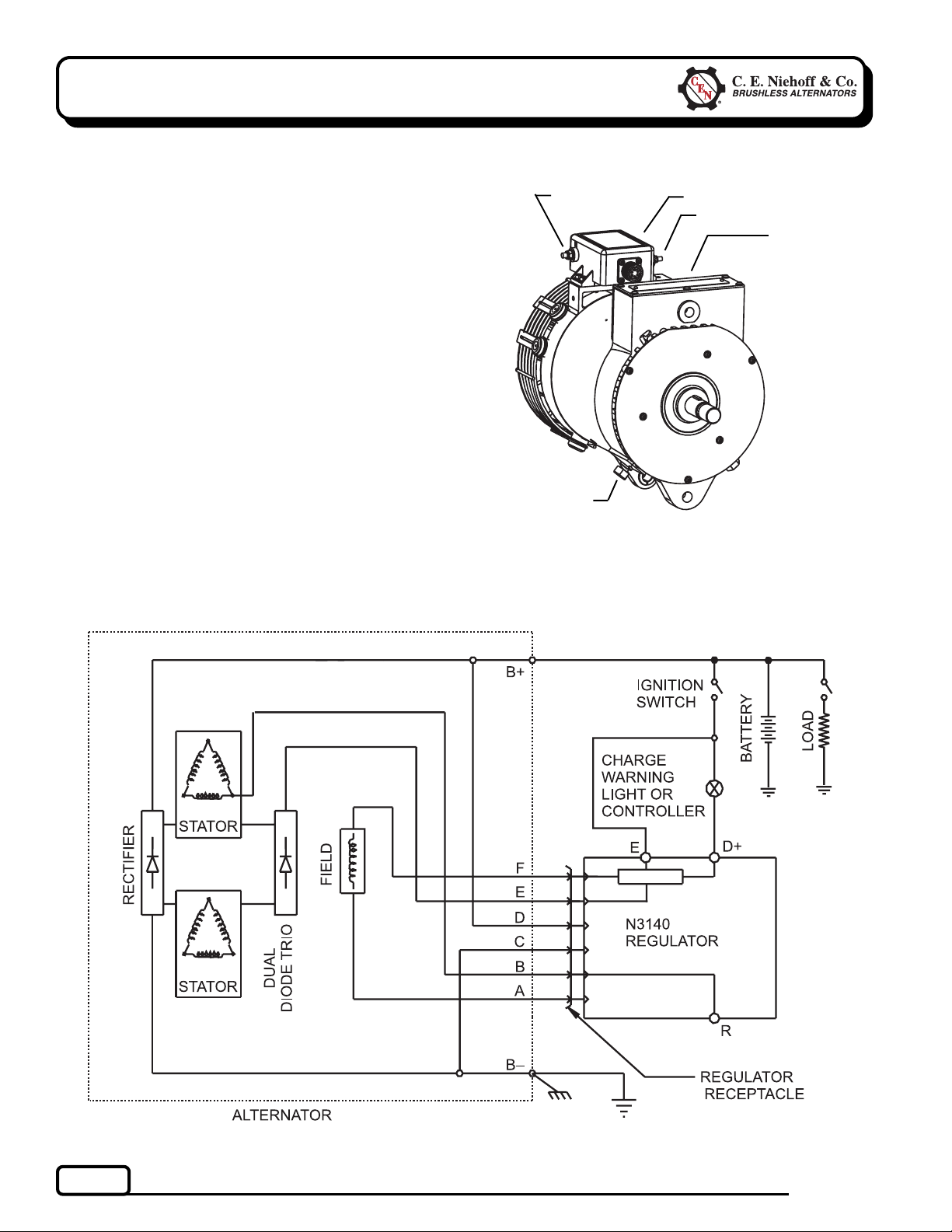
Section 1: Wiring Diagrams
CEN N1233-2 Alternator
Description and Operation
N1233-2 28 V (260 A) alternator is self-rectifying.
All windings and current-transmitting components
are non-moving, so there are no brushes or slip rings
to wear out.
When controlled by the N3140 regulator, this alternator becomes externally energized through the E
terminal, connected to a switched power source to
turn on regulator. See wiring diagram. N3140 regulator has:
• D+ terminal to provide signal to vehicle electrical
system, confirming alternator operation.
• R terminal to provide an optional AC voltage tap.
• overvoltage cutout (OVCO). Regulators with OVCO
(overvoltage cutout) will trip at vehicle electrical
system voltages above 33 volts that exist longer
than 3 seconds. OVCO feature detects high
voltage and reacts by signaling relay in F+
alternator circuit to open. This turns off alternator. Restarting engine resets OVCO circuit.
Regulator regains control of alternator output
voltage.
R terminal
!!
!
!!
!!
!
!!
!!
!
!!
B– terminal
stud
Figure 1 — N1233-2 Alternator Terminals
(N3140 Regulator Attached to Alternator)
!!
!
!!
!!
!
!!
D+ terminal
E terminal
B+ terminal stud
(on rear of
control unit)
Page 2
Figure 2 — N1233-2 Alternator with N3140 Regulator
TG0021A
Page 3
Section 2: Basic Troubleshooting
A . Tools and Equipment for J ob
• Digital Multimeter (DMM)
• Ammeter (digital, inductive)
• Jumper wires
B. Identification Record
List the following for proper troubleshooting:
Alternator model number ____________________
❏
Regulator model number _____________________
❏
Setpoints listed on regulator__________________
❏
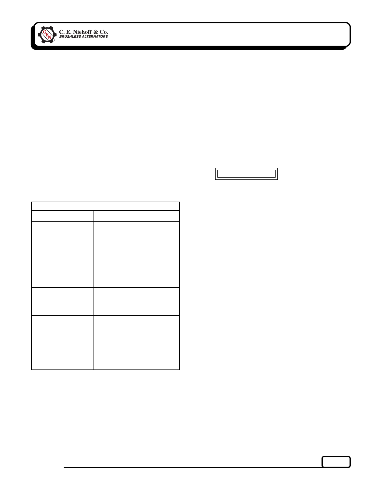
C. Preliminary Check-out
Check symptoms in Table 1 and correct if necessary.
TABLE 1 – System Conditions
SYMPTOM
Low V oltage Output
High V oltage Output
No V oltage Output
Check:loose drive belt; low
battery state of charge.
Check:current load on system
is greater than alternator can
produce.
Check:defective wiring or poor
ground path; low regulator
setpoint.
Check:defective alternator and/
or regulator.
Check:wrong regulator.
Check:high regulator setpoint.
Check:defective regulator.
Check:alternator.
Check:broken drive belt.
Check:battery voltage at alter-
nator output terminal.
Check:defective alternator
and/or regulator.
Check:lost residual magnetism
in self-energizing alternator.
Go to Chart 1, page 4.
ACTION
2. Inspect all vehicle battery connections
Connections must be clean and tight.
3. Determine battery voltage and state of charge
If batteries are discharged, recharge or replace
batteries as necessary. Electrical system cannot
be properly tested unless batteries are charged
95% or higher. In addition, open circuit voltages
must be within ± 0.2 V.
4. Connect meters to alternator
Connect red lead of DMM to alternator B+ terminal and black lead to alternator B– terminal.
Clamp inductive ammeter on B+ cable.
5. Operate vehicle
Observe charge voltage.
CAUTION
shut down system. Electrical system damage may occur if
charging system is allowed to operate at high voltage. Go to
Table 1 at left.
If charge voltage is above
33 volts, immediately
If voltage is at or below regulator setpoint, let
charging system operate for several minutes to
normalize operating temperature.
6. Observe charge volts and amps
Charge voltage should increase and chargeamps
should decrease. If charge voltage does not increase within ten minutes, continue to next step.
7. Batteries are considered fully charged if charge
voltage is at regulator setpoint and charge amps
remain at lowest value for 10 minutes.
8. If charging system is not performing properly,
go to Chart 1, page 4.
9. Check OVCO circuit
Shut down vehicle and restart engine. If alternator functions normally after restart, a “no output
condition” was a normal response of voltage
regulator to “high voltage” condition. Inspect
condition of electrical system, including loose
battery cables, both positive and negative. If
battery disconnects from system, it could cause
“high voltage” condition in electrical system,
causing OVCO circuit to trip.
D. Basic T roubleshooting
1. Inspect charging system components for
damage
Check connections at B– cable, B+ cable, and
alternator-to-regulator harness. Repair or
replace any damaged component before troubleshooting.
TG0021A
If you have reset alternator once, and electrical
system returns to normal charge voltage condition, there may have been a one time, high voltage spike, causing OVCO circuit to trip.
If OVCO circuit repeats cutout a second time in
short succession and shuts off alternator F+
circuit, try third restart. If OVCO circuit repeats
cutout, go to Chart 2, page 5.
Page 3
Page 4

Section 3: Advanced Troubleshooting
Chart 1 – No Output
Self-energized alternator may have lost magnetism. Touch steel tool to shaft to detect
any magnetism. Is shaft magnetized?
Yes
!!
!
!!
Install a jumper from B+ terminal on alternator to
E terminal on regulator. Momentarily (1 sec.) jumper
E terminal on regulator to D+ terminal on regulator.
Touch shaft with steel tool to detect significant magnetism. Is shaft magnetized?
Yes
!!
!
!!
Unplug alternator-to-regulator harness.
Connect DMM across pin D and pin C in
harness plug. Does battery voltage exist?
Yes
Alternator is defective.
!!
!
!!
Set DMM to diode test. Connect black lead
of DMM to pin E in harness plug. Connect
red lead to B-terminal or alternator. DMM
should read voltage drop. Reverse leads.
DMM should read OL.
Yes
Alternator is defective.
!!
!
!!
Repair vehicle circuit to E terminal. Vehicle
charging circuit test is complete.
Unplug alternator-to-regulator harness. Connect
DMM across pin D and pin C in harness plug.
Does battery voltage exist?
Yes
!!
!
!!
Install a jumper from pin F in harness plug to B+
terminal on alternator. Momentarily (1 sec.)
jumper pin A in harness plug to alternator B–
terminal. Touch shaft with steel tool to detect
significant magnetism. Is shaft magnetized?
Yes
!!
!
!!
Regulator is defective.
No
!!
!
!!
No
!!
!
!!
Alternator is defective.
Alternator is defective.
No
!!
!
!!
No
!!
!
!!
No
!!
!
!!
No
!!
!
!!
Install a jumper from B+ terminal on alternator to
E terminal on regulator. Momentarily (1 sec.) jumper
E terminal on regulator to D+ terminal on regulator.
Touch shaft with steel tool to detect significant magnetism. Is shaft magnetized?
Yes
!!
!
!!
Retest alternator.
Unplug alternator-to-regulator harness. Connect
DMM across pin D and pin C in harness plug.
Does battery voltage exist?
Yes
Alternator is defective.
!!
!
!!
Set DMM to diode test. Connect black lead of DMM
to pin E in harness plug. Connect red lead to Bterminal or alternator. DMM should read voltage
drop. Reverse leads. DMM should read OL.
Yes
Alternator is defective.
!!
!
!!
Install a jumper from pin F in harness plug to B+
terminal on alternator. Momentarily (1 sec.) jumper
pin A in harness plug to alternator B– terminal.
Touch shaft with steel tool to detect significant
magnetism. Is shaft magnetized?
Yes
!!
!
!!
Regulator is defective.
PIN CONNECTIONS
Figure 3 – Alternator-to-Regulator Harness Plug
Alternator is defective.
Pin A F–
Pin B Phase
Pin C B–
Pin D B+
Pin E D+
Pin F F+
No
!!
!
!!
No
!!
!
!!
No
!!
!
!!
No
!!
!
!!
Page 4
TG0021A
Page 5

Section 3: Advanced Troubleshooting
Chart 2 – No Alternator Output – Test OVCO Circuit
With engine off, unplug alternator-to-regulator harness. Connect DMM red lead to pin A on harness plug.
Connect black lead to pin F on same plug. Does resistance measure about 1.2 (± 0.2) ohms?
(CONT’D)
Yes
!!
!
!!
Connect DMM red lead to pin A on alternator-toregulator harness plug. Connect black lead to
alternator B– terminal. Does continuity exist?
Yes
!!
!
!!
Alternator is defective.
Regulator is defective.
No
!!
!
!!
Figure 4 – Alternator-to-Regulator Harness Plug
Alternator is defective.
PIN CONNECTIONS
Pin A F–
Pin B Phase
Pin C B–
Pin D B+
Pin E D+
Pin F F+
No
!!
!
!!
TG0021A
Page 5
Page 6

Notes
Page 6
TG0021A
Page 7

Notes
TG0021A
Page 7
Page 8

Notes
If you have questions about your alternator or any of these test procedures, or if you need to locate a Factory Authorized Service Distributor, please contact us at:
TEL: 800.643.4633 USA and Canada • TEL: 847.866.6030 outside USA and Canada • FAX: 847.492.1242
Page 8
C. E. Niehoff & Co.• 2021 Lee Street • Evanston, IL 60202 USA
E-mail us at support@ceniehoff.com
TG0021A
 Loading...