

Page 1
N1128-1 Alternator
.
C. E. Niehoff & Co
BRUSHLESS ALTERNATORS
w/Red B+ Link or w/ Wire Assembly
Replacement Instructions
For N1128-1 with serial numbers 0010 through 0059:
If red B+ link needs to be replaced (see Figure 1):
Red B+ link is no longer available as a replacement part. Install new B+ wire assembly as described below:
1. Remove ADE cover plate and save hardware for reassembly.
2. Disconnect regulator harness wiring connections from diode modules. Leave field coil F– lead connection intact
and disconnect field coil F+ lead from diode module.
3. Remove and discard red B+ link.
4. Remove and save the hardware attaching the diode module marked with an "X" in Figure 1 and the ground link
connected to it. Discard the metal thermally conductive strip between the diode module and the black heat sink
and replace with a new one. Rotate the diode module so the printed diode schematic side is on top. Reinstall the
ground link in the position shown in Figure 2 on page 2.Torque diode module mounting screws to 12.5-13.6 Nm/
9-10 lb. ft.
5. Go to "If B+ wire assembly needs to be replaced" on page 2, starting with step 4.
If diode module needs to be replaced (see Figure 1):
Red B+ link should be replaced with new B+ wire assembly when replacing any diode module.
Replace diode module and install new B+ wire assembly as described below:
1. Follow steps 1-3 in "If red B+ link needs to be replaced" above.
2. If replacing diode module marked with an "X" in Figure 1, follow step 4 in "If red B+ link needs to be replaced"
above to install the new diode module on the existing black heat sink.
If replacing one of the other two diode modules, the diode module marked with an "X" in Figure 1 must still be
changed as described in step 4, since the new B+ wire assembly will be replacing the existing B+ link. Then follow
the same steps to replace the other defective diode module, but don't rotate the new diode module.
3. Go to "If B+ wire assembly needs to be replaced" on page 2, starting with step 4.
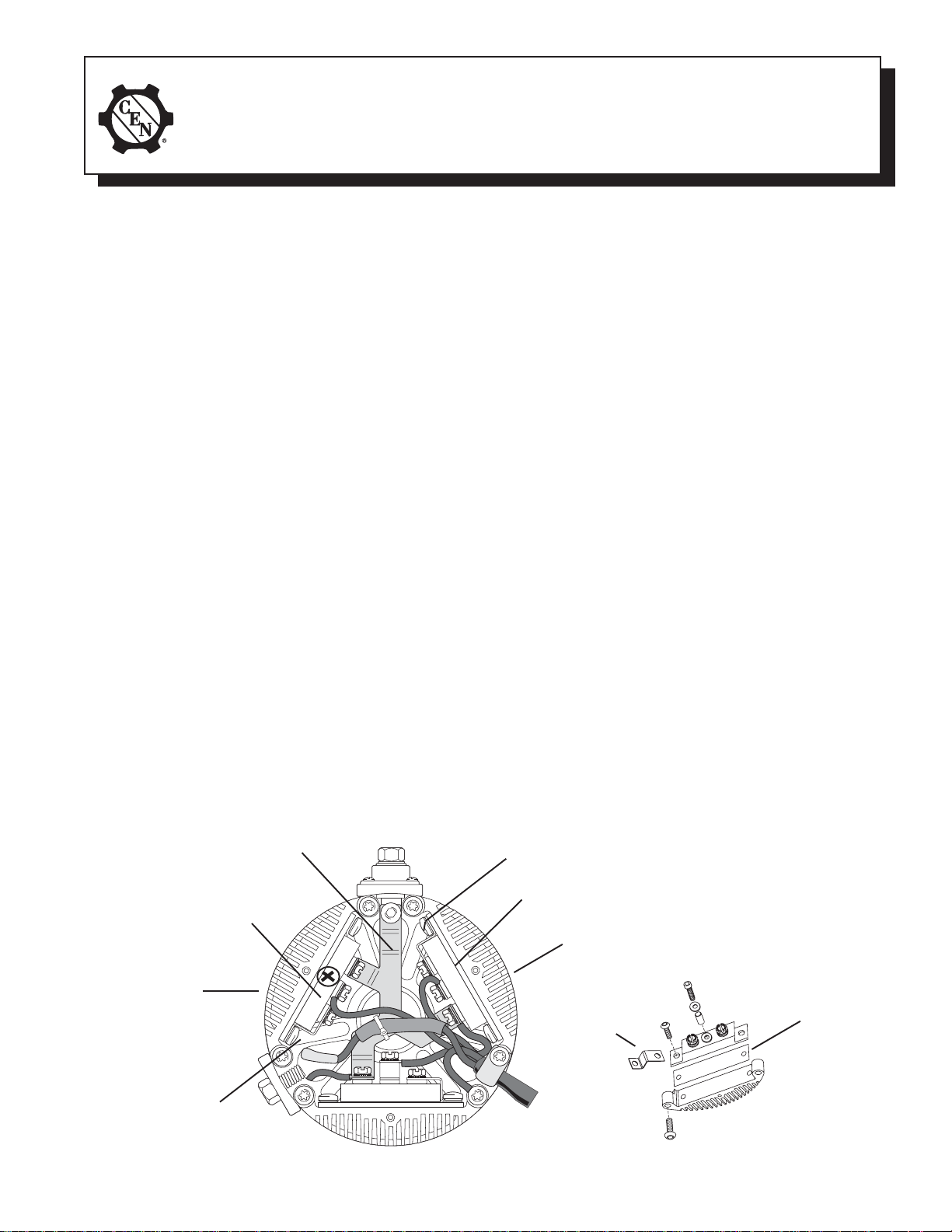
Diode module
Black heat sink
Red B+ link
➛
➛
➛
➛
➛
➛
Ground link
Diode module
Black heat sink
➛
Ground link
➛
➛
Metal
thermally
conductive
strip
Ground link
Figure 1 – N1 128-1 Alternator with Red B+ Link
II0084APage 1 of 2
Page 2
For N1128-1 with serial numbers higher than 0059:
If B+ wire assembly needs to be replaced (see Figure 2):
Install new B+ wire assembly as described below:
1. Remove ADE cover plate and save hardware for reassembly.
2. Disconnect regulator harness wiring connections from diode modules. Leave field coil F– lead connection intact
and disconnect field coil F+ lead from diode module.
3. Remove and discard defective B+ wire assembly.
4. Connect new B+ wire assembly:
a. To B+ stud and torque screw to 28-29 Nm/21-22 lb. ft.
b. To diode modules and torque all screws to 4 Nm/35 lb. in.
5. Connect regulator harness to module screws and torque screws to 4 Nm/35 lb. in. Connect green ground wire to
heat sink and torque screw to 13.5 Nm/10 lb. ft.
6. Affix wire tie to field coil lead and one phase lead.
7. Using DMM (digital multimeter) set on diode test, connect red lead to B+ teminal on alternator and connect black
lead to B– terminal on alternator. Meter should read OL (blocking). Reverse leads, meter should read less than
0.8 V (flow). If meter reads zero in either direction, recheck wiring connections and diode orientation.
If diode module needs to be replaced (see Figure 2):
Replace diode module and install wire assembly as described below:
1. Follow steps 1-2 in "If B+ wire assembly needs to be replaced" above.
2. Remove and save B+ wire assembly.
3. Remove and save the hardware attaching the defective diode module and the ground link connected to it. Discard
the metal thermally conductive strip between the diode module and the black heat sink and replace with a new one.
Reinstall the ground link in the position shown in Figure 2 below. Torque diode module mounting screws to
12.5-13.6 Nm/ 9-10 lb. ft.
4. Continue with step 4 in "If B+ wire assembly needs to be replaced" above.
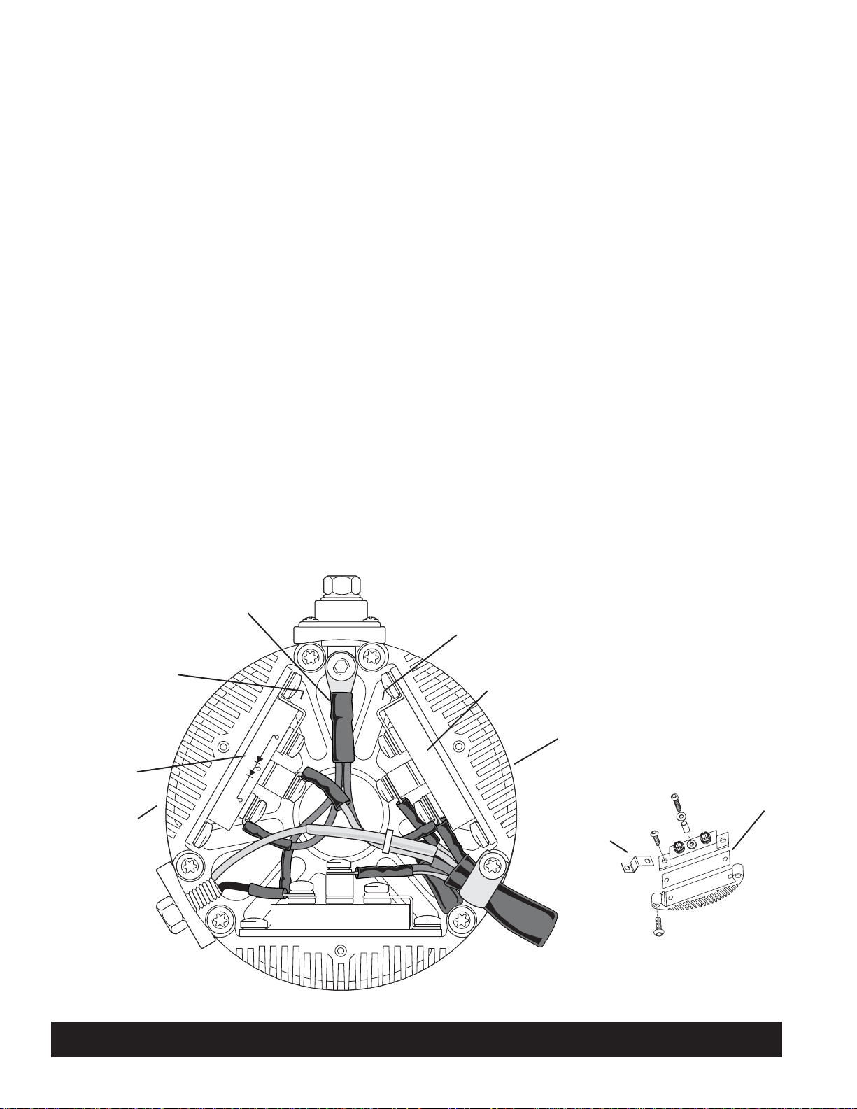
Ground link
Diode module
Black heat sink
B+ wire assembly
➛
Ground link
➛
➛
➛
Diode module
➛
➛
Figure 2 – N1 128-1 Alternator with B+ Wire Assembly
➛
Black heat sink
Ground link
➛
Metal
thermally
conductive
strip
➛
C. E. Niehoff & Co. • 2021 Lee Street • Evanston, IL 60202 Tech Services Hotline 800-643-4633
II0084APage 2 of 2
 Loading...