

Page 1
Troubleshooting Guide
for EPM Electric Power Manager
Hazard Defi nitions
These terms are used to bring attention to presence of hazards
of various risk levels or to important information concerning
product life.
Indicates presence of hazard(s) that
WARNING
can cause severe personal injury,
death or substantial property damage
if ignored.
Indicates presence of hazard(s) that
CAUTION
can cause minor personal injury or
property damage if ignored.
Indicates special instructions on
NOTICE
installation, operation or mainte nance that are important but not
related to personal injury hazards.
Table of Contents
Section A: Component Description ............................... 2
Section A: Start-up/Shutdown Procedures .................... 2
Section B: CAN/J1939 Diagnostics ............................... 3
Section C: Basic Troubleshooting ................................. 4
Section D: Troubleshooting the EPM ......................... 5-7
Battery Conditions
Until temperatures of electrical
NOTICE
system components stabilize, these
conditions may be observed during
cold start voltage tests.
• Maintenance/Low Maintenance Battery:
— Immediately after engine starts, system volts
measure lower than regulator setpoint and
system amps measure at a medium level.
— 3-5 minutes into charge cycle, volts increase and
amps decrease.
— 5-10 minutes into charge cycle, volts reach
regulator setpoint or very close, and amps
decrease to a minimum.
— Low maintenance battery has same characteris tics with slightly longer recharge times.
• Maintenance-free Battery:
— Immediately after engine starts, system volts
measure lower than regulator setpoint with low
charging amps.
— Once the charge cycle begins, low volts and low
amps are still present.
— After the alternator energizes, voltage will
increase several tenths. Amps will increase
gradually, then quickly, to medium to high amps.
— Finally, volts will increase to setpoint and amps
will decrease.
The time it takes to reach optimum voltage and
amperage will vary with engine speed, load, and
ambient temperature.
• High-cycle Maintenance-free Battery:
— These batteries respond better than standard
maintenance-free. Charge acceptance of these
batteries may display characteristics similar to
maintenance batteries.
Battery Charge Volt and Amp Values
Volt and amp levels fluctuate depending on the battery
state of charge. If batteries are in a state of discharge—
as after extended cranking time to start the engine—
system volts will measure lower than the regulator setpoint after the engine is restarted and system amps will
measure higher. This is a normal condition for the
charging system; the greater the battery discharge level,
the lower the system volts and the higher the system
amps. The volt and amp readings will change as batteries recover and become fully charged: system volts will
increase to regulator setpoint and system amps will
decrease to low level (depending on other loads).
• Low Amps: Minimum or lowest charging system
amp value required to maintain battery state of
charge, obtained when testing the charging system
with a fully charged battery and no other loads
applied. This value will vary with battery type.
• Medium Amps: System amps value which can cause
the battery temperature to rise above adequate
charging temperature within 4-8 hours of charge
time. To prevent battery damage, the charge amps
should be reduced when battery temperature rises.
Check battery manufacturer’s recommendations for
proper charge amp rates.
• High Amps: System amps value which can cause
the battery temperature to rise above adequate
charging temperature within 2-3 hours of charge
time. To prevent battery damage, the charge amps
should be reduced when battery temperature rises.
Check battery manufacturer’s recommendations for
proper charge amp rates.
• Battery Voltage: Steady-state voltage value as measured with battery in open circuit with no battery
load. This value relates to battery state of charge.
• Charge Voltage: Voltage value obtained when the
charging system is operating. This value will be
higher than battery voltage and must never exceed
the regulator voltage setpoint.
• B+ Voltage: Voltage value obtained when measuring
voltage at battery positive terminal or alternator B+
terminal.
• Surface Charge: Higher than normal battery voltage
occurring when the battery is disconnected from
battery charger. The surface charge must be removed
to determine true battery voltage and state of charge.
• Significant Magnetism: Change in strength or
intensity of a magnetic field present in alternator
rotor shaft when the field coil is energized. The
magnetic field strength when the field coil is energized should feel stronger than when the field is not
energized.
• Voltage Droop or Sag: Normal condition occurring
when the load demand on alternator is greater than
rated alternator output at given rotor shaft RPM.
TG0051A
Page 1
Page 2

Section A: Component Description and Operation
EPM Description and Operation
EPM Electric Power Manager used with these units
• is rated for continuous current at 200 A on 28 V
side. The 14 V side is rated for continuous current
at 100 A.
• manually connects batteries after battery connect
switch on vehicle is pressed.
• automatically disconnects batteries from vehicle
loads 3 minutes after engine shuts down.
• provides 28 V auxillary output power for up to four
20 A channels and 14 V auxillary output power for
one 20 A channel, protected by an internal, resettable, electronic circuit breaker.
• keeps batteries connected to system when emergency
flashers are activated.
Normal Start-Up Procedure
1. Press the vehicle battery-connect switch for about
one second to connect batteries to electrical system.
2. Turn START-RUN switch to RUN.
3. Wait until glow plug light goes off.
4. Turn START-RUN switch to START and crank
engine.
5. Return switch to RUN when engine starts.
6. If engine fails to crank, turn START-RUN switch to
OFF, repeat steps 1-5 above.
Emergency Start-Up Procedure
WARNING
1. Connect slave vehicle Nato connector to vehicle.
2. Follow steps 2-5 under “Normal Start-Up Procedure.”
3. Disconnect slave NATO connector after engine is
running.
This procedure will bypass EPM
and batteries in system. Use this
procedure ONLY when vehicle
must be removed immediately from
location in an EMERGENCY.
Shutdown Procedure
1. Place gear shift in park or neutral and set parking
brake.
2. Turn start-run switch to OFF to stop engine.
3. Batteries will be disconnected from vehicle in 3 min.
unless emergency flashers are on, then batteries
will stay connected until f lashers are turned off
or battery is discharged.
Page 2
Figure 1 – Battery Connect Switch
TG0051A
Page 3
Section B: CAN/J1939 Diagnostics
CAN/J1939 Interface
DESCRIPTION AND OPERATION
The EPM is compatible with CAN bus standard for digital
networks and uses the SAE J1939 communications protocol.
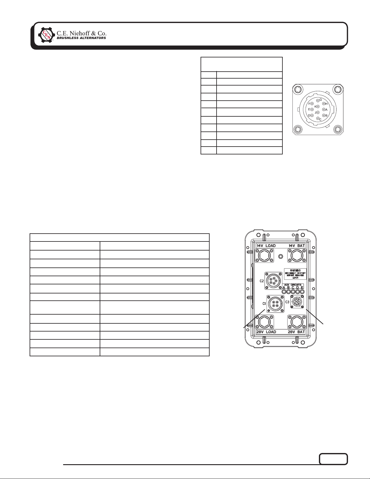
CEN uses MIL-STD connector MS3112E12-10P to interface
between the EPM and the DPA adapter used to monitor the
broadcast messages on the CAN bus line. The readouts of
these messages are shown in Table 2 for the EPM.
TABLE 1 – J1939 Connector
Circuit Identifi cation
Pin
A
B
C
D
E
F
G
H
J
K
Identifi cation
CAN High
CAN Low
CAN Shield
Ground
Restricted use
Restricted use
Restricted use
unused
unused
+28V p o wer
Figure 2 – J1939
Connector Pins
TABLE 2 – EPM/J1939 Readout Diagnostics (With Engine Running)
EPM Readout
Load Voltage 28 V System
Load Voltage 14 V System
Alternator Speed
Battery Voltage 28 V System
Battery Voltage 14 V System
EPM Temperature
Charging and Discha rging
Current of 28 V Battery
Batt Charging 28 V LED
Batt Charging 14 V LED
Main Switches On
Cranking Detected
Emergency Flasher Detected
10 A (varies according to battery condition)
Expected Reading
27–29 V
13.5–14.5 V
1200 to 6000 RPM
27–29 V
13.5–14.5 V
–50ºF (–46ºC) to 200ºF (93ºC)
OK
OK
OK
OK
OK
T
EPM
Connector
to
Regulator
Figure 3 – EPM Electric Power Manager
T
J1939
Connector
Under Cap
TG0051A
Page 3
Page 4

Section C: Basic Troubleshooting
Tools and Equipment for Job
• Digital Multimeter (DMM)
• Ammeter (digital, inductive)
• Jumper wires
If no tools are available, monitor LED code.
Basic Troubleshooting
1. Inspect charging system components
Check connections at ground cables, positive
cables, and regulator harness. Repair or replace
any damaged component before troubleshooting.
2. Inspect EPM connections
Connections must be in proper sequence and
clean and tight. See Figure 4, page 5.
3. Inspect connections of vehicle batteries
Connections must be clean and tight.
4. Determine battery type, voltage, and state
of charge
Batteries must be all the same type for system
operation. If batteries are discharged, recharge or
replace batteries as necessary. Electrical system
cannot be properly tested unless batteries are
charged 95% or higher. See page 1 for details.
Page 4
TG0051A
Page 5

Section D: Troubleshooting the EPM
EPM Electric Power Manager
DESCRIPTION AND OPERATION
Main diagnostic feature of the EPM is a green LED
located on the top of the device. The EPM connects and
disconnects batteries based on operational requirements.
EPM also allows batteryless operation until vehicle is
shut off.
TABLE 3 – EPM LED Diagnostics
EPM LED COLOR EPM STATUS
Off (Clear)
Flashing GREEN
Steady GREEN
TABLE 4 – EPM Harness Plug
Pin
Battery Ground
A
Alternator Phase Signal
B
Energize (Active Low) Signal
C
Ignition Signal
D
EPM is not energized or EPM is
defective.
Batteries connected for 3 minutes
for engine starting after battery
connect switch pressed.
Normal operation (batteries are
connected to the system and
engine is running)
Socket Functions
Function
TABLE 5 – AUX Circuit and LED Functions
(Max. 30 A)
Pin
A
B
C
D
E
EPM LED
AUX
Circuits
Connector
EPM
Connector
Function
14 V
28 V
28 V
28 V
28 V
LED Color
Normally On
GREEN
GREEN
GREEN
GREEN
GREEN
T
T
T
If LED
OFF:
A short or overcurrent
may have occurred.
Check AUX load wiring
and reset EPM by
pressing battery
connect switch
T
T
Figure 4 – EPM Electric Power Manager
Aux. Load
Diagnostic
LEDs
J1939
Connector
Under Cap
(see p. 3 for
details)
TG0051A
BATTERY CONNECT SWITCH
EPM
EPM
EPM
Figure 5 – EPM System Schematic
Page 5
Page 6

Section D: Troubleshooting the EPM
(CONT’D)
CAUTION
Troubleshooting sequences must be performed during 3-minute delay after battery connect switch on vehicle
is pressed. If main LED on EPM is not fl ashing GREEN, press switch to reactivate system. LED on EPM must be
fl ashing GREEN while performing tests.
Chart 1 – Engine Will Not Crank at Start-Up
Before Troubleshooting, Check Batteries for Proper Charge Voltage. See Page 1.
Turn START-RUN switch to OFF. Press vehicle battery connect switch. Check LED on EPM.
Yes No
T
Check for continuity across 28 V and 14 V terminals
on EPM. Does continuity exist?
Yes
T
Check and repair
starter and starter
wiring as necessary.
Re-test.
No
T
EPM is
defective.
Is LED flashing GREEN?
T
Disconnect 4-socket harness at EPM. While pressing vehicle battery connect switch, check for continuity between socket C on EPM harness plug and
ground. Does continuity exist?
Yes No
T
EPM is
defective.
Check and repair
vehicle battery
connect switch and
wiring as necessary.
Re-test.
T
Chart 2 – No Power to Aux. Loads –One or More LEDs are OFF
Before Troubleshooting, Check Batteries for Proper Charge Voltage. See Page 1.
Disconnect Aux. Load harness from EPM. Turn start-run switch to OFF.
Press vehicle battery connect switch. Is LED on EPM flashing GREEN?
Yes
T
Are all five Aux diagnostic LEDs lit on EPM?
Yes
T
Check and repair
load and load wiring
as necessary.
Re-test.
No
T
EPM is
defective.
No
T
EPM is
defective.
Page 6
TG0051A
Page 7

Section D: Troubleshooting the EPM
Chart 3 – 28V Only – EPM Sequence of Operation
If emergency flashers are the
Vehicle battery connect switch
is pressed.
3-Minute counter in EPM starts.
T
Batteries are connected
T
Flashing GREEN
T
START-RUN Switch operated to start vehicle
T
Batteries will stay connected as long as vehicle is running or
emergency flashers are on
T
only load required, engine does
not need to be started to keep
batteries connected.
After f lashers are switched on,
EPM will keep power to loads
until batteries are discharged.
(CONT’D)
T
T
T
3-Minute delay in EPM ends
T
AUX LEDs Steady GREEN
AUX Current available
T
Normal operation
T
Shut down vehicle
T
Flashing GREEN
T
3-Minute Delay
T
3-Minute Delay Ends and EPM disconnects batteries
T
EPM and AUX Diagnostic LEDs OFF.
AUX Channels still available.
T
If you have questions about your alternator or a ny of these test proce dures, or if you need to locate a Factory Authorized Service Dealer, please contact us at:
C. E. Niehoff & Co.• 2021 Lee Street • Evanston, IL 60202 USA
TEL: 800.643.4633 USA and Canada • TEL: 847.866.6030 outside USA and Canada • FAX: 847.492.1242
E-mail us at support@CENiehoff.com
TG0051A
Page 7
 Loading...