

Page 1
C810 Alternator
with External Rectifi er Assembly
Installation Instructions
This symbol is used to indicate
CAUTION
presence of hazards that can cause
minor property damage.
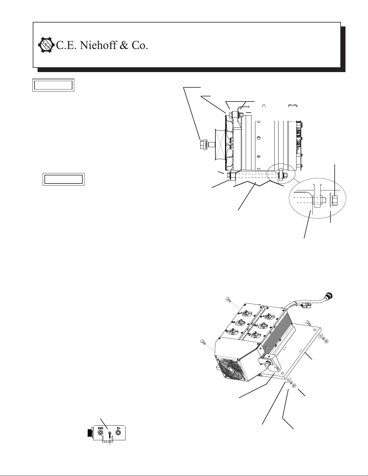
C810 Alternator
1. C810 alternator has 7” hinge mount.
2. Units are shipped with shaft collar, hardened
washer and locknut. Remove and discard shaft
collar. Install pulley and furnished hardened
washer. Torque locknut to 163 Nm/ 120 lb. ft.
3. Use hardened washers between aluminum surfaces and bolt heads and nuts. See Figure 1 for
torque.
Slip bushing in lower rear
CAUTION
mounting lug must be securely
tightened against mounting
bracket on engine. Failure to
do so can result in broken
mounting lugs or broken upper
mounting bracket.
External Rectifier Assembly
1. Mounting location of external rectifier assembly
should provide proper cooling and protect rectifier from direct water, road debris, or chemicals.
It can be mounted horizontally or vertically.
2. Using the standard A9-4026 wiring harness, the
external rectifier assembly can be mounted up to
7 feet away from the alternator.
3. Use hardened washers between aluminum
surfaces and bolt heads and nuts. See Figure 2
for torque values.
4. Use a suitable adhesive such as Loctite
or equivalent on bolts. Follow manufacturer’s
instructions.
Regulator
1. Regulator is located on the bracket that supports
the external rectifier assembly (see Figures 2 and
4).
2. If P terminal is used (located on opposite side of
D+ and IGN terminals), regulator will need to be
removed and electrical connection to P terminal
installed. See step 7 in “Electrical Connections.”
3. See Figure 3 for torque values.
4. Make sure regulator harness is securely plugged
into regulator receptacle. See Figure 4.
M5 x .80 screw (4 places) – torque to 8.5 Nm/75 lb. in.
®
222
M20x1.5 nut and disk spring washer—
torque to 163 Nm/120 lb.ft.
M10/0.3750 in. Mounting bolt (2 plcs)
Hardened washers
M10/0.3750 in. Locknut (2 plcs)–
torque to 38 Nm/29 lb. ft.
M12/0.50 in.
Mounting bolt
Hardened
washer
Alternator mounting
bracket on engine
Slip bushing must be tightened against bracket —
see “CAUTION” at left
Bracket
on engine
Figure 1 - C810 Alternator Installation
13 mm/0.5 in.
Mounting bolt
grade 5 or better
(4 places)
M12/0.50
lock nut –
torque to
88 Nm/65 lb. ft.
Regulator
mounting holes
Locknut –
torque to
54 Nm/40 lb.ft.
Hardened
washer
Page 1 of 2
Figure 3 - Regulator Installation
Flat
washer
Lockwasher
Figure 2 - External Rectifi er Assembly Installation
II170A
Page 2
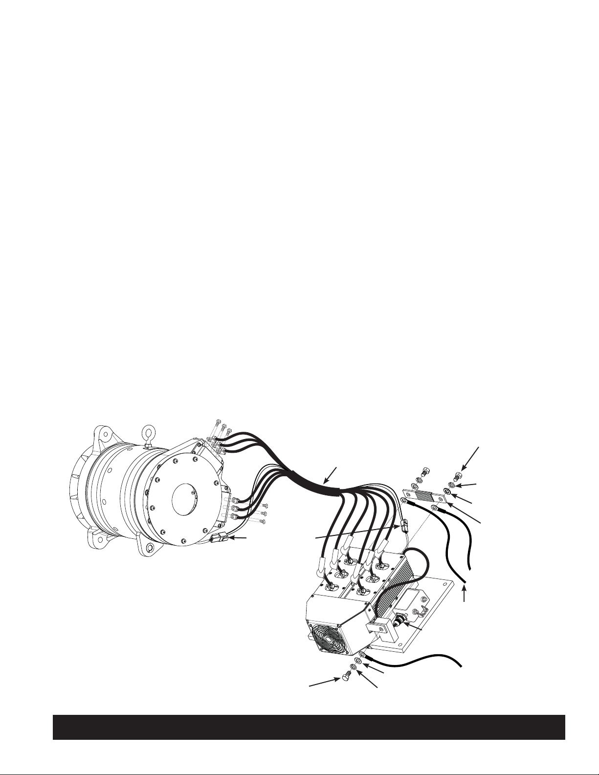
Electrical Connections
1. Connect phase harness between alternator and
rectifier as shown in Figure 4: P1 to P1, P2 to P2,
and P3 to P3 for each set of three cables. Do not
cross the connections between sets of three.
Secure with hardware and use torque values
shown.
2. Securely connect gray field receptacles at
alternator and at external rectifier assembly.
3. Connect B+ and B- terminals. See Figure 4.
Make sure insulated sleeve is in place on busbar.
Choose wire gauge for B+ and B– cables capable
of handling maximum alternator output with
minimum voltage drop.
4. If an additional cable connection is necessary,
connect where/as shown. See Figure 4.
5. All output leads must be supported within
305 mm/12 in. of termination and cabling,
wiring, or conduit run supported at 406 mm/
16 in. maximum intervals. Strain relief must be
provided and cable ties used.
6. Connect IGN terminal on regulator to ignition
source. Torque M5 terminal nut to 4.5 Nm/
40 lb. in.
7. Connect optional P terminal to tachometer or relay.
See step 2 in “Regulator.” Torque M6 terminal nut
to 4.5 Nm/40 lb.in.
8. Connect optional D+ terminal (provides 28 VDC
sense voltage) to multiplex controller. When
connecting D+ terminal to controller through a
relay, the relay coil must be diode protected and
rated for proper voltage. Torque M6 terminal nut
to 4.5 Nm/40 lb. in.
Sealing Wiring Connections
On ALL metallic electrical connections to external
rectifier assembly (including B+ and B– connections),
alternator, regulator, and their harness connectors,
apply Dow Corning® 1-2577 Low VOC RTV coating or
equivalent. Do not use coating containing acetic acid
(vinegar smell) on electrical components.
Phase terminal bolts connected to alternator (6 places) –
torque to 9 Nm/80 lb. in.
P3
P2
P1
P3
P2
P1
Field receptacles
Phase terminal bolts connected
to rectifi er (6 places) –
torque to 8 Nm/70 lb. in.
1/2-13 x 1.75 B- bolt
torqued to 30 Nm/22 lb. ft.
Phase
harness
P1
P2
P3
P1
P2
P3
Flat washer
Lockwasher
1/2-13 x 1 B+ bolt torqued
to 30 Nm/22 lb. ft. (2 plcs)
Lockwasher (2 plcs)
Flat washer (2 plcs)
Busbar with
insulated sleeve
Battery B+ cable
primary location
Additional cable
location, as needed
Regulator harness
Battery B- cable location
Figure 4 - Electrical Connections
C. E. Niehoff & Co. • 2021 Lee Street • Evanston, IL 60202 Tech Services Hotline 800-643-4633
Page 2 of 2
II170A
 Loading...