

Page 1
C802/C802D/C802TD/C820 Alternators
Troubleshooting Guide
Hazard Defi nitions
These terms are used to bring attention to presence of hazards
of various risk levels or to important information concerning
product life.
Indicates presence of hazard(s)
CAUTION
that will or can cause minor personal
injury or property damage if ignored.
Indicates special instructions on
NOTICE
installation, operation or mainte nance that are important but not
related to personal injury hazards.
Table of Contents
Section A: Wiring Diagram ......................................2 – 3
Section B: Basic Troubleshooting ................................. 4
Section C: Advanced Troubleshooting ...................5 – 10
Battery Conditions
Until temperatures of electrical
NOTICE
system components stabilize, these
conditions may be observed during
cold start voltage tests.
• Maintenance/Low Maintenance Battery:
— Immediately after engine starts, system volts
measure lower than regulator setpoint and
system amps measure at a medium level.
— 3-5 minutes into charge cycle, volts increase and
amps decrease.
— 5-10 minutes into charge cycle, volts reach
regulator setpoint or very close, and amps
decrease to a minimum.
— Low maintenance battery has same characteris tics with slightly longer recharge times.
• Maintenance-free Battery:
— Immediately after engine starts, system volts
measure lower than regulator setpoint with low
charging amps.
— Once the charge cycle begins, low volts and low
amps are still present.
— After the alternator energizes, voltage will
increase several tenths. Amps will increase
gradually, then quickly, to medium to high amps.
— Finally, volts will increase to setpoint and amps
will decrease.
The time it takes to reach optimum voltage and amperage will vary with engine speed, load, and ambient
temperature.
• High-cycle Maintenance-free Battery:
— These batteries respond better than standard
maintenance-free. Charge acceptance of these
batteries may display characteristics similar to
maintenance batteries.
Charge Volt and Amp Values
Volt and amp levels fluctuate depending on the battery
state of charge. If batteries are in a state of discharge—
as after extended cranking time to start the engine—
system volts will measure lower than the regulator setpoint after the engine is restarted and system amps will
measure higher. This is a normal condition for the
charging system; the greater the battery discharge level,
the lower the system volts and the higher the system
amps. The volt and amp readings will change as batteries recover and become fully charged: system volts will
increase to regulator setpoint and system amps will
decrease to low level (depending on other loads).
• Low Amps: Minimum or lowest charging system
amp value required to maintain battery state of
charge, obtained when testing the charging system
with a fully charged battery and no other loads
applied. This value will vary with battery type.
• Medium Amps: System amps value which can cause
the battery temperature to rise above adequate
charging temperature within 4-8 hours of charge
time. To prevent battery damage, the charge amps
should be reduced when battery temperature rises.
Check battery manufacturer’s recommendations for
proper charge amp rates.
• High Amps: System amps value which can cause
the battery temperature to rise above adequate
charging temperature within 2-3 hours of charge
time. To prevent battery damage, the charge amps
should be reduced when battery temperature rises.
Check battery manufacturer’s recommendations for
proper charge amp rates.
• Battery Voltage: Steady-state voltage value as measured with battery in open circuit with no battery
load. This value relates to battery state of charge.
• Charge Voltage: Voltage value obtained when the
charging system is operating. This value will be
higher than battery voltage and must never exceed
the regulator voltage setpoint.
• B+ Voltage: Voltage value obtained when measuring
voltage at battery positive terminal or alternator B+
terminal.
• Surface Charge: Higher than normal battery voltage
occurring when the battery is disconnected from
battery charger. The surface charge must be removed
to determine true battery voltage and state of charge.
• Significant Magnetism: Change in strength or
intensity of a magnetic field present in alternator
rotor shaft when the field coil is energized. The
magnetic field strength when the field coil is energized should feel stronger than when the field is not
energized.
• Voltage Droop or Sag: Normal condition occurring
when the load demand on alternator is greater than
rated alternator output at given rotor shaft RPM.
TG0004E
Page 1
Page 2
Section A: Wiring Diagram
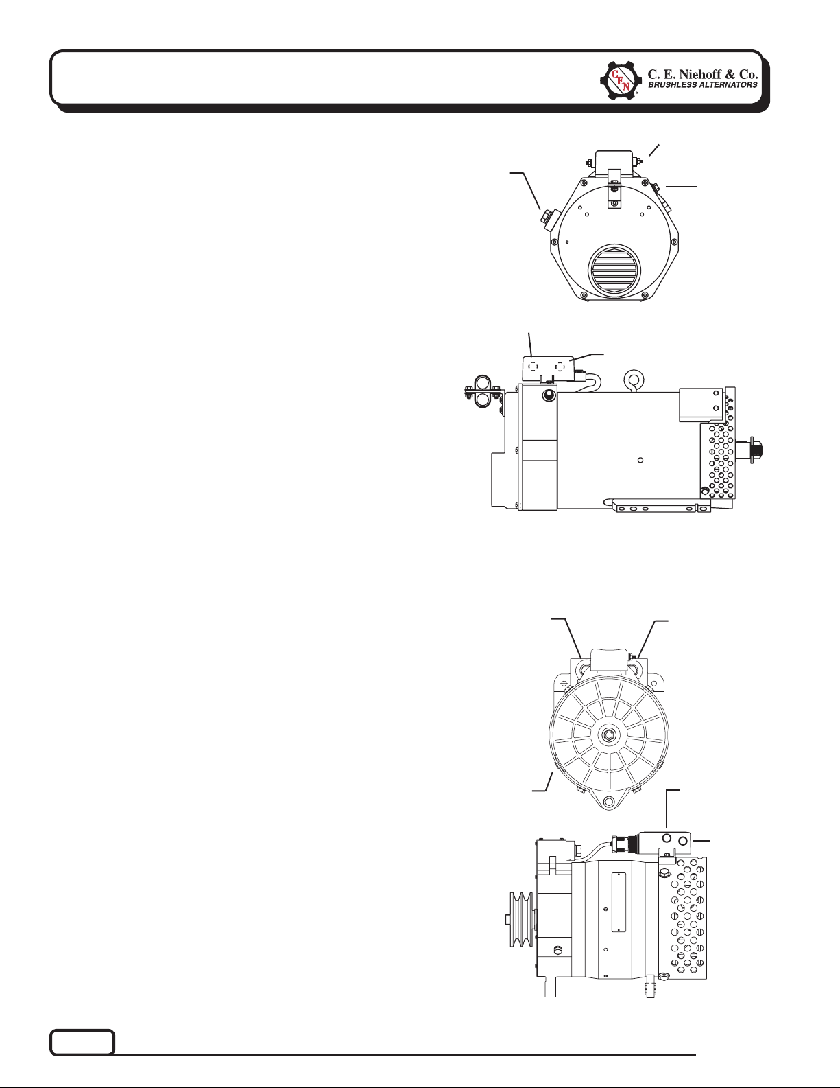
CEN C802, C802D, and C802TD Alternators
Description and Operation
C802, C802D, and C802TD 28 V, 450 A alternators are
internally rectified. All windings and current-transmitting
components are non-moving, so there are no brushes or
slip rings to wear out. Energize switch activates regulator.
Field coil is then energized. Regulator maintains alternator output voltage at regulated setting as vehicle electrical
loads are switched on and off. Alternator output current
is self-limiting and will not exceed rated capacity of alternator.
A2-213 regulator furnished with these units has a D+
terminal that can provide signal to vehicle electrical
system, confirming alternator operation. Regulator also
provide overvoltage cutout (OVCO). Regulator also has a
P terminal that can provide an optional AC voltage tap
and an IGN terminal. See page 5 for description and
operation of LED on this regulator.
B+ Terminal
D+ Terminal
P Terminal
T
T
T
T
Figure 1 — C802/C802D/C802TD
IGN Terminal
T
B– Terminal
CEN C820 Alternator
Description and Operation
C820 28 V/14 V, 150 A/150 A alternator is internally
rectified. All windings and current-transmitting
components are non-moving, so there are no brushes
or slip rings to wear out. Energize switch activates
regulator. Field coil then ramps up to full power within
30 seconds (as a function of the regulator). Upper voltage
(28 V) is rectified with standard diodes. Lower voltage
(14 V) circuit output current is controlled by SCRs in
the drive end housing.
A2-303 regulator furnished with this unit maintains
alternator output voltage at regulated setting as vehicle
electrical loads are switched on and off. Alternator
output current is self-limiting and will not exceed
rated capacity of alternator.
14 V
B+ Terminal
B– Terminal
(either side)
28 V
B+ Terminal
T
T
T
F– Sense
Terminal
(Optional)
T
T
IGN
Terminal
Page 2
Figure 2 — C820
TG0004E
Page 3
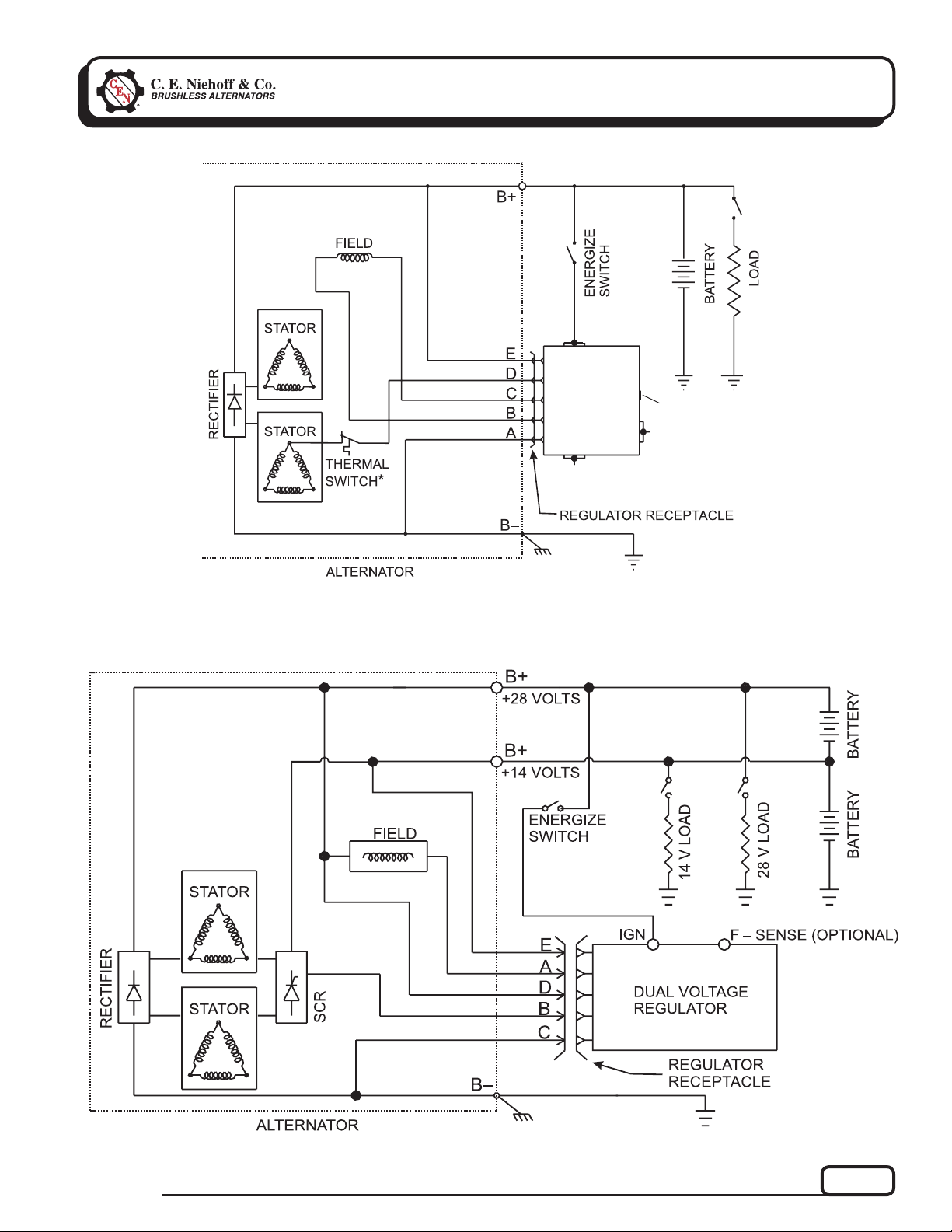
Section A: Wiring Diagram
IGN
(CONT’D)
*Thermal switch is not
factory-installed on all models.
Figure 3 — C802/C802D/C802TD Alternator with Regulator
A2-213
REGULATOR
D+
W
GREEN LENS LED
P
TG0004E
Figure 4 — C820 Alternator with Regulator
Page 3
Page 4

Section B: Basic Troubleshooting
Tools and Equipment for Job
• Digital Multimeter (DMM)
• Ammeter (digital, inductive)
• CEN Regulator Bypass Adapter A10-129
• Jumper wire
Identifi cation Record
List the following for proper troubleshooting:
Alternator model number _________________________
T
Regulator model number ________________________
T
Setpoints listed on regulator _____________________
T
Preliminary Check-out
Check symptoms in Table 1 and correct if necessary.
TABLE 1 – System Conditions
SYMPTOM ACTION
Low Voltage Output
High Voltage Output
No Voltage Output
No Air-Conditioning/
Alt. Warning Light On
(C802 only)
No 14 V Output
(C820 only)
Check: loose drive belt; low bat-
tery state of charge.
Check: current load on system
is greater than alternator can
produce.
Check: defective wiring or poor
ground path; low regulator
setpoint.
Check: defective or damaged
alternator and/or regulator.
Check: wrong regulator.
Check: high regulator setpoint.
Check: C802 only—OVCO
tripped.
Check: defective regulator.
Check: alternator.
Check: broken drive belt.
Check: battery voltage at alter-
nator output terminal.
Check: defective alternator
and/or regulator.
CAUTION
If alternator warning light on
vehicle is ON, do not operate
vehicle until troubleshooting
resolves the condition.
Check: defective alternator or
regulator. Go to Chart 2,
page 7.
Check: defective regulator.
Go to Chart 5, page 10.
Failure to check for the following
NOTICE
conditions will result in erroneous
test results in the troubleshooting
charts.
Basic Troubleshooting
1. Inspect charging system components for damage
Check connections at B– cable, B+ cable, and
regulator harness. Also check connections at
regulator terminal wiring from regulator to vehicle
components. Repair or replace any damaged
component before electrical troubleshooting.
2. Inspect vehicle battery connections
Connections must be clean and tight.
3. Check drive belt
Repair or replace as necessary.
4. Determine battery voltage and state of charge
If batteries are discharged, recharge or replace
batteries as necessary. Electrical system cannot be
properly tested unless batteries are charged 95% or
higher.
5. Connect meters to alternator
Connect red lead of DMM to alternator B+
terminal and black lead to alternator B– terminal.
Clamp inductive ammeter on B+ cable.
6. Operate vehicle
Observe charge voltage.
If charge voltage is above
32 volts, immediately shut
down system. Electrical
system damage may occur if
charging system is allowed to
operate at high voltage.
Go to Table 1.
If voltage is at or below regulator setpoint, let
charging system operate for several minutes to
normalize operating temperature.
7. Observe charge volts and amps
Charge voltage should increase and charge amps
should decrease. If charge voltage does not
increase within ten minutes, continue to next step.
8. Battery is considered fully charged if charge
voltage is at regulator setpoint and charge amps
remain at lowest value for 10 minutes.
9. If charging system is not performing properly,
go to:
• C802 — Chart 2, page 7.
• C820 — Chart 4, page 9.
CAUTION
Page 4
TG0004E
Page 5

Section C: Advanced Troubleshooting
A2-213 Regulator on C802 Alternator
DESCRIPTION AND OPERATION
A2-213 regulator is either attached directly to the outside of C802 alternator or remote-mounted.
Main diagnostic feature of regulator is a green lens LED
located on the front of the regulator. LED indicates
whether regulator has been energized. See Table 2 for
LED indication and status.
Regulators with OVCO (overvoltage cutout) will trip at
vehicle electrical system voltages above 32 volts that
exist longer than 3 seconds. OVCO feature detects high
voltage and reacts by signaling the F+ alternator circuit
to open. This turns off alternator. Restarting engine
resets OVCO circuit. Regulator regains control of alternator output voltage.
TABLE 2—A2-213 Regulator
LED Indications and Status
INDICATION STATUS
ON steady Normal regulator operation.
Alternator is producing output.
FLASHING Regulator is receiving energize
signal. LED will flash until
alternator produces output.
OFF Regulator is not receiving ener-
gize signal or OVCO has tripped.
Troubleshooting
Shut down vehicle and restart engine. If alternator functions normally after restart, a “no output condition” was
normal response of voltage regulator to “high voltage”
condition. Inspect condition of electrical system, including loose battery cables, both positive and negative. If
battery disconnects from system, it could cause “high
voltage” condition in electrical system, causing OVCO
circuit to trip.
If you have reset alternator once and electrical system
returns to normal charge voltage condition, there may
have been a one time, high voltage spike, causing OVCO
circuit to trip.
If OVCO circuit repeats cutout a second time in short
succession and shuts off alternator F+ circuit, try third
restart. If OVCO circuit repeats cutout, go to page 7.
REMOTE-MOUNTED REGULATORS: CHECK
CONDITION OF FUSE IN WIRING HARNESS
BEFORE TROUBLESHOOTING
TG0004E
Page 5
Page 6

Section 3: Advanced Troubleshooting
Chart 1 – C802 – No Air-Conditioning /NO ALT OUTPUT Light On
With engine running, verify operation of charging system. Is regulator setpoint voltage present?
(CONT’D)
Yes
Go to Chart 2, page 7.
T
Connect DMM red lead to D+ (or P) terminal on regulator. Connect black lead
to alternator B– terminal.
At D+ terminal – is regulator setpoint voltage present?
At P terminal – is 12 V to 18 V present?
Yes
No
T
Stop engine. Alternator is good.
Check vehicle wiring.
T
Stop engine. Unplug alternator-to-regulator harness. Set DMM to Diode Test.
Connect DMM red lead to socket D on alternator-to-regulator harness plug.
Connect red lead to alternator B+ terminal. Does continuity exist?
Yes
T
Regulator is defective.
Go to Chart 3, page 8.
No
T
No
T
SOCKET CONNECTIONS
Socket A B–
Socket B Field +
Socket C Field –
Socket D AC
Socket E B+
Figure 5 – Alternator-to-Regulator Harness Plug
Page 6
TG0004E
Page 7

Section 3: Advanced Troubleshooting
(CONT’D)
Chart 2 – C802 – No Alternator Output – Test Charging Circuit
STATIC TEST – ENGINE OFF, BATTERY SWITCH ON, KEY ON.
REMOTE-MOUNTED REGULATORS: CHECK CONDITION OF FUSE IN WIRING HARNESS
BEFORE TROUBLESHOOTING
Test for battery voltage at alternator B+ terminal. Does battery voltage exist?
Yes
No
T
With engine running: Test for battery voltage at
regulator IGN terminal. Does battery voltage exist?
Yes
No
T
T
Stop engine. Unplug alternator-to-regulator harness. Connect DMM red lead to socket E in harness plug.
Connect black lead to socket A in same plug. Does battery voltage exist?
Yes
T
Connect DMM red lead to socket D in harness plug. Connect
black lead to alternator B+ terminal. Does continuity exist?
Yes
No
Alternator is defective.
T
Repair vehicle wiring as necessary.
Continue test.
Repair vehicle wiring as necessary.
T
Continue test.
T
No
T
T
Go to Chart 3, page 8.
T
Connect DMM red lead to socket B on alternator-to-regulator harness plug. Connect black lead to socket C
on same plug. Does resistance measure about 1.2 ohms?
Yes
No
T
Alternator is defective.
T
Unplug alternator-to-regulator harness. Plug CEN Regulator Bypass Adapter A10-129 into harness plug.
Make sure black lead does not touch ground. Clip red lead to B+ terminal on alternator. (If Adapter is not
available, connect jumper wire from pin B on harness to alternator B+ terminal.) Does spark occur at
alternator B+ terminal?
Yes
T
Disconnect Adapter or jumper
wire. Alternator is defective.
SOCKET CONNECTIONS
Socket A B–
Socket B Field +
Socket C Field –
Socket D AC
Socket E B+
Figure 6 – Alternator-to-Regulator Harness Plug
TG0004E
No
T
Momentarily (1 sec) touch black lead to ground on alternator
case. [If Adapter is not available, momentarily (1 sec.)
connect jumper wire from pin C on harness to ground.]
Spark will occur at ground. Touch steel tool to shaft to detect
significant magnetism. Is shaft magnetized?
Yes
T
Disconnect Adapter or
jumper wire. Regulator
is defective.
Disconnect Adapter or
jumper wire. Alternator
is defective.
No
T
Page 7
Page 8

Section 3: Advanced Troubleshooting
(CONT’D)
Chart 3 – C802 – Continuation of Chart 1 or 2 as Noted
Set DMM to diode test. Connect black lead of DMM to B+ terminal on alternator. Connect
red lead to socket D on harness plug. DMM should read voltage drop. Reverse leads. DMM
should read OL.
Yes
T
Repair vehicle circuit to IGN terminal. Vehicle
charging circuit test is complete.
SOCKET CONNECTIONS
Socket A B–
Socket B Field +
Socket C Field –
Socket D AC
Socket E B+
Figure 7 – Alternator-to-Regulator Harness Plug
No
T
Check continuity of thermal switch inside rectifier
housing assembly: Remove anti-drive end duct
housing on alternator. With DMM, check continuity
between socket D on harness plug and diode
shown in Figure 8 below. Does continuity exist?
Yes
T
Alternator is
defective.
Thermal switch
in control unit
is defective.
No
T
USE THIS DIODE
T
Figure 8 – Diode Arrangement inside Anti-Drive End Housing
Page 8
TG0004E
Page 9

Section 3: Advanced Troubleshooting
Chart 4 – C820 – No Alternator Output – Test Charging Circuit
STATIC TEST – ENGINE OFF, BATTERY SWITCH ON, KEY ON
Test for battery voltage at both alternator 28 V and 14 V B+ terminals. Does battery voltage exist at both terminals?
(CONT’D)
Yes
No
T
Repair vehicle wiring as necessary. Continue test.
T
Jumper 28 V B+ terminal on alternator to IGN terminal on regulator. Field coil may take 30 seconds to reach full
power. Touch shaft with steel tool to detect significant magnetism. Is shaft magnetized?
Yes
T
Unplug alternator-to-regulator harness. Touch shaft with
steel tool to detect significant magnetism.
Is shaft magnetized?
Yes
No
T
Alternator is defective.
T
Reconnect harness. Go to energize switch on engine
in IGN circuit. Test for battery voltage going into energize
switch from battery. Does battery voltage exist?
Yes
Repair vehicle circuit to
energize switch. Continue test.
No
T
Disconnect jumper wire. Connect DMM red lead
to pin D in alternator-to-regulator harness plug.
Connect black lead to pin C in same plug. Does
battery voltage exist?
TT
Make sure jumper wire from alternator 28 V B+ terminal
to regulator IGN terminal is still attached.
Test for battery voltage at energize switch IGN terminal connection. Does battery voltage exist at energize switch?
Yes
T
IGN circuit from regulator
to energize switch is good.
Energize switch is defective.
Repair vehicle circuit
from IGN terminal on
regulator to energize
switch on engine.
T
Vehicle charging circuit test is complete. Remove jumper
wire used in testing. Run engine and
re-test charging circuit for operation.
No
T
T
Disconnect jumper wire. Connect DMM red lead
to pin E in alternator-to-regulator harness plug.
Connect black lead to pin C in same plug. Does
battery voltage exist?
Regulator is defective.
Figure 9 – Alternator-to-Regulator Harness Plug
T
No
T
Momentarily (1 sec.) connect jumper wire
from pin A in harness plug to B– terminal
on alternator. Spark will occur. Touch steel
tool to shaft to detect significant magnetism.
Is shaft magnetized?
Yes
No
T
Disconnect jumper
wire. Alternator is
defective.
T
Yes
No
T
Alternator is defective.
T
Yes
T
PIN CONNECTIONS
Pin A F–
Pin B SCR Gate
Pin C B–
Pin D 28 V B+
Pin E 14V B+
No
T
Alternator is
defective.
TG0004E
Page 9
Page 10

Section 3: Advanced Troubleshooting
(CONT’D)
Chart 5 – A2-303 Regulator – No 14 V Alternator Output – Test Circuit
With engine off, is battery voltage present at alternator 14 V B+ terminal?
Yes
No
Connect DMM red lead to pin E on alternator-to-regulator harness plug.
Connect black lead to pin C on same plug.
Does battery voltage exist? See Figure 9, page 9.
Yes
No
T
T
Substitute a known good regulator. Run engine. Is regulator setpoint voltage present?
Yes
T
Original regulator was defective.
Alternator is defective.
T
Repair vehicle wiring as necessary.
T
Continue test.
Alternator is defective.
T
No
T
If you have questions about you r alternator or any of these test procedures, or if you need to locate a Factory Author ized Service Dist ributor, please contact us at:
C. E. Niehoff & Co.• 2021 Lee Street • Evanston, IL 60202 USA
TEL: 800.643.4633 USA and Canada • TEL: 847.866.6030 outside USA and Canada • FAX: 847.492.1242
E-mail us: support@CENiehoff.com OR Visit our Web site: www.CENiehoff.com
Page 10
TG0004E
 Loading...