

Page 1
C. E. Niehoff & Co
.
BRUSHLESS ALTERNATORS
C722/C722-1 Alternators
Installation Instructions
CAUTION
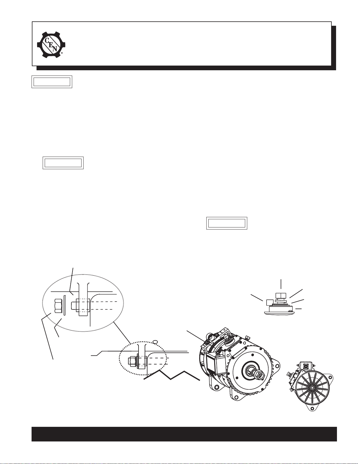
1. Install alternator as shown in Figure 1. Alternator
has two pairs of mounting lugs, so it can be
either right or left mounted. One of the oppo-
site mounting lugs can be used for tensioner.
When adjusting belt tension, mounting foot
hardware must be loosened. After belt tension is
adjusted or when mounting alternator, tighten
drive end mounting hardware before anti-drive
end hardware.
CAUTION
a. Use hardened washers between aluminum
surfaces and bolt heads and nuts.
b. OEM units are shipped with pulley, hardened
washer and locknut installed.
c. Aftermarket units are shipped with shaft
collar, hardened washer and locknut. Remove
and discard shaft collar. Install pulley and
furnished hardened washer.Torque locknut to
163 Nm/120 lb. ft.
Slip bushing must be tightened against
bracket — see “CAUTION” above
This symbol is used to indicate
presence of hazards that can cause
minor property damage.
Slip bushing located in anti-drive
end mounting lug must be
securely tightened against
alternator mounting bracket
on engine. Failure to do so can
result in broken mounting lugs.
d. Follow vehicle manufacturer’s recommendations
for belt tension.
2. All cabling, wiring or conduit must be supported
within 305 mm/12 in. of termination on alternator.
Mounting screws on cable clamp should be torqued
to 15 Nm/130 lb. in.
3. Choose wire gauge capable of handling maximum
alternator output with no more than 0.4 V drop on
each leg from alternator to battery.
4. Regulator is furnished on OEM units and is supplied
separately by request with aftermarket units. Mounting screws on regulator should be torqued to 8.5
Nm/75 lb. in.
5. Regulator electrical connections:
a. Make sure alternator-to-regulator harness
plug is secure in regulator receptacle.
b. A2-212 regulator has R (or W) and D+ 6mm
stud terminals, and an E 5mm stud terminal.
Torque terminal nuts to 4.5 Nm/40 lb. in.
CAUTION
Make sure regulator wiring is
connected to the correct terminals
otherwise permanent damage will
occur. R (or W) terminal has voltage
limiter that limits output voltage to
8V peak. Output voltage frequency
(Hz) = alternator rpm/10.
12mm x1.75 bolt –
torque to 32 Nm/24 lb. ft.
TT
T
TT
TT
TT
T
TT
T
TT
Hardened washer
12mm/0.50 Locknut –
torque to
88 Nm/65 lb. ft.
Alternator has two pairs of mounting lugs, so it
can be either right or left mounted. One of the
opposite mounting lugs can be used for
tensioner.
Battery output
cable terminal
(AWG 0000)
Regulator mounting screws –
torque to
8.5 Nm/75 lb. in.
T
TT
TT
Bracket
on engine
Figure 1 - C722 Alternator Installation Details
T
TT
TT
Alternator B+
Terminal Stud
B– terminal 10mm locknut –
torque to 15 Nm/11 lb. ft.
TT
T
TT
Lockwasher
Washer
TT
TT
T
TT
TT
T
Insulator
TT
TT
T
ADE View
C722
C. E. Niehoff & Co. • 2021 Lee Street • Evanston, IL 60202 Tech Services Hotline 800-643-4633
Page 1 of 1
II0062B
 Loading...