

Page 1
C. E. Niehoff & Co.
BRUSHLESS ALTERNATORS
700 Series Troubleshooting Guide
for C715 and C716 Alternators
Hazard Definitions
These terms are used to bring attention to presence of hazards
of various risk levels or to important information concerning
product life.
CAUTION
personal injury or property damage if ignored.
NOTICE
maintenance that are important but not related to
personal injury hazards.
Indicates presence of hazards
that will or can cause minor
Indicates special instructions
on installation, operation or
Table of Contents
Section 1: Wiring Diagram ...................................... 2
Section 2: Basic Troubleshooting ............................ 3
Section 3: Advanced Troubleshooting ................4 – 6
Battery Conditions
NOTICE
conditions may be observed during cold start voltage tests.
• Maintenance/low maintenance battery:
— Immediately after engine starts, system volts
are lower than regulator setpoint with medium
amps.
— 3-5 minutes into charge cycle, higher system
volts and reduced amps.
— 5-10 minutes into charge cycle, system volts
are at, or nearly at, regulator setpoint, and
amps are reduced to a minimum.
— Low maintenance battery has same charac-
teristics with slightly longer recharge times.
• Maintenance-free battery:
— Immediately after engine start, system volts are
lower than regulator setpoint with low amps.
— 15-30 minutes into charge cycle, still low volts
and low amps.
— 15-30 minutes into charge cycle, volts increase
several tenths. Amps increase gradually, then
quickly to medium to high amps.
— 20-35 minutes into charge cycle, volts increase
to setpoint and amps decrease.
• High-cycle maintenance-free battery:
— These batteries respond better than standard
maintenance-free. Charge acceptance of these
batteries may display characteristics similar to
maintenance batteries.
Until temperatures of electrical
system components stabilize, these
Charge Volt and Amp Values
The volt and amp levels are a function of the batterystate of charge. If batteries are in a state of discharge,
as after extended cranking time to start the engine,
the system volts, when measured after the engine is
started will be lower than the regulator set point and
the system amps will be high. This is a normal
condition for the charging system. The measured
values of system volts and amps will depend on the
level of battery discharge, in other words, the greater
the battery discharge level the lower the system volts
and higher the system amps will be. The volt and
amp readings will change and system volts reading
will increase up to regulator set point and the system
amps will decrease to low level (depending on other
loads) as the batteries recover and become fully
charged.
Low Amps:Low Amps:
•
Low Amps: A minimum or lowest charging system
Low Amps:Low Amps:
amp value required to maintain battery state of
charge, obtained when testing the charging system
with a fully charged battery and no other loads
applied. This value will vary with battery type.
Medium Amps:Medium Amps:
•
Medium Amps: A system amps value which can
Medium Amps:Medium Amps:
cause the battery temperature to rise above the
adequate charging temperature within 4-8 hours
of charge time. To prevent battery damage the
charge amps should be reduced when battery
temperature rises. Check battery manufacturer’s
recommendations for proper charge amps rates.
High Amps:High Amps:
•
High Amps: A system amps value which can cause
High Amps:High Amps:
the battery temperature to rise above adequate
charging temperature within 2-3 hours. To prevent
battery damage the charge amps should be
reduced when the battery temperature rises.
Check battery manufacturer’s recommendations
for proper charge amp rates.
Battery Voltage:Battery Voltage:
•
Battery Voltage: Steady-state voltage value as
Battery Voltage:Battery Voltage:
measured with battery in open circuit with no
battery load. This value relates to battery-state of
charge.
Charge Voltage:Charge Voltage:
•
Charge Voltage: A voltage value obtained when
Charge Voltage:Charge Voltage:
the charging system is operating. This value will
be higher than battery voltage and must never
exceed the regulator voltage set point.
B+ Voltage:B+ Voltage:
•
B+ Voltage: A voltage value obtained when mea-
B+ Voltage:B+ Voltage:
suring voltage at battery positive terminal or
alternator B+ terminal.
Surface Charge:Surface Charge:
•
Surface Charge: A higher than normal battery
Surface Charge:Surface Charge:
voltage occurring when the battery is removed
from a battery charger. The surface charge must
be removed to determine true battery voltage and
state of charge.
Significant Magnetism:Significant Magnetism:
•
Significant Magnetism: A change in the strength
Significant Magnetism:Significant Magnetism:
or intensity of a magnetic field present in the
alternator rotor shaft when the field coil is energized. The magnetic field strength when the field
coil is energized should feel stronger than when
the field is not energized.
Voltage Droop or Sag: Voltage Droop or Sag:
•
Voltage Droop or Sag: A normal condition which
Voltage Droop or Sag: Voltage Droop or Sag:
occurs when the load demand on the alternator is
greater than rated alternator output at given rotor
shaft RPM.
TG0007A
Page 1
Page 2
Section 1: Wiring Diagram
C. E. Niehoff & Co.
BRUSHLESS ALTERNATORS
CEN C715 and C716 Alternators
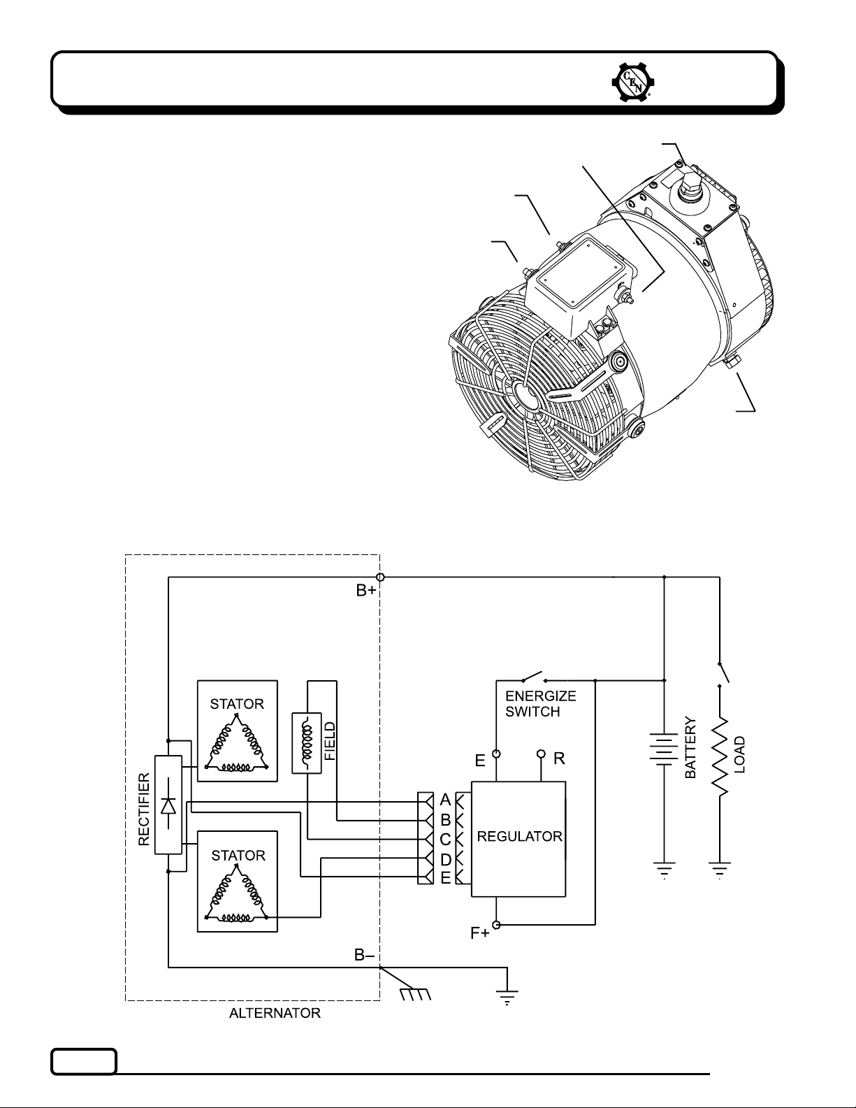
Description and Operation
C715C715
The
C715 alternator (14 V, 360 A) and
C715C715
tor (14 V, 400 A) are internally rectified. All windings
and current-transmitting components are nonmoving, so there are no brushes or slip rings to wear
out. This unit is externally energized through either
an ignition switch or an energize switch (commonly
an oil pressure switch), which activates regulator.
Field coil is then energized. Regulator maintains
alternator output voltage at regulated setting as
vehicle electrical loads are switched on and off.
Alternator output current is self-limiting and will not
exceed rated capacity of alternator.
A2-128 regulator used with all units has R terminal
for optional AC voltage tap. A 15.5 V regulator setpoint is available for battery isolator applications.
Electromagnetic interference (EMI) is suppressed with
internal filters to acceptable levels defined by the
Society of Automotive Engineers (SAE) specification
J1113/41. A2-128 regulator will not reduce EMI from
sources such as antennas, poor cable routing practice, or other electronic devices that cause EMI. If EMI
continues, consult an electromagnetic compliance
(EMC) specialist to determine EMI source.
C716C716
C716 alterna-
C716C716
B+ Terminal
E Terminal
R Terminal
F+ Terminal
G
G
G
G
G
B Terminal
Figure 1 C715/C716 Alternator with A2-128 Regulator
Page 2
Figure 2 C715/C716 Wiring Diagram
TG0007A
Page 3
C. E. Niehoff & Co.
BRUSHLESS ALTERNATORS
Section 2: Basic Troubleshooting
A. Tools and Equipment for Job
• Digital Multimeter (DMM)
• Ammeter (digital, inductive)
• CEN Regulator Bypass Adapter A10-129
• Jumper wire
• 12 V test light
B. Identification Record
Complete the following for proper troubleshooting:
Alternator model number ______________________
o
Regulator model number _______________________
o
Setpoints listed on regulator ___________________
o
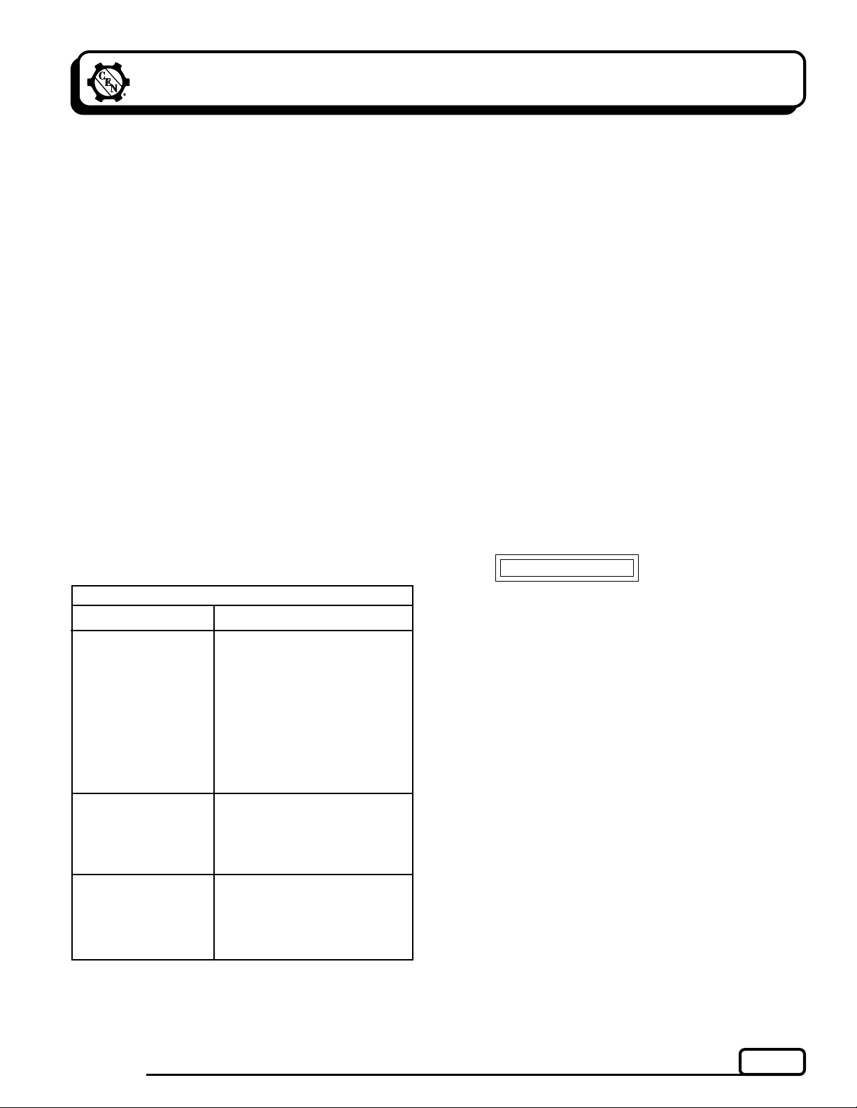
C. Preliminary Check-out
Check condition of items in Table 1 and correct if
necessary.
TABLE 1 System Conditions
SYMPTOM
Low Voltage Output
High Voltage Output
No Voltage Output
Check: loose drive belt; low
battery state of charge.
Check: current load on
system is greater than
alternator can produce.
Check: defective wiring or
poor ground path; low
regulator setpoint.
Check: defective alternator
and/or regulator.
Check: wrong regulator.
Check: high regulator set-
point.
Check: defective regulator.
Check: alternator.
Check: broken drive belt.
Check: battery voltage at
alternator output terminal.
Check: defective alternator
and/or regulator.
ACTION
D. Basic Troubleshooting
Inspect charging system componentsInspect charging system components
1.
Inspect charging system components
Inspect charging system componentsInspect charging system components
for damagefor damage
for damage
for damagefor damage
Check connections at B– cable, B+ cable, and
regulator harness. Repair or replace any damaged component before troubleshooting.
Inspect vehicle battery connectionsInspect vehicle battery connections
2.
Inspect vehicle battery connections
Inspect vehicle battery connectionsInspect vehicle battery connections
Connections must be clean and tight.
Determine battery voltage and state of chargeDetermine battery voltage and state of charge
3.
Determine battery voltage and state of charge
Determine battery voltage and state of chargeDetermine battery voltage and state of charge
If batteries are discharged, recharge or replace
batteries as necessary. Electrical system cannot
be properly tested unless batteries are charged
95% or higher.
Determine if battery isolator is usedDetermine if battery isolator is used
4.
Determine if battery isolator is used
Determine if battery isolator is usedDetermine if battery isolator is used
charging circuitcharging circuit
charging circuit
charging circuitcharging circuit
Check vehicle wiring diagram. If so, you must
jumper out isolator before troubleshooting. See
Chart 1 on page 4 for details.
Connect meters to alternatorConnect meters to alternator
5.
Connect meters to alternator
Connect meters to alternatorConnect meters to alternator
Connect red lead of DMM to alternator B+
terminal and black lead to alternator B–
terminal. Clamp inductive ammeter on B+ cable.
Operate vehicleOperate vehicle
6.
Operate vehicle
Operate vehicleOperate vehicle
Observe charge voltage.
CAUTION
shut down system. Electrical system damage may occur if
charging system is allowed to operate at high voltage. Go to
Table 1 at left.
If voltage is at or below regulator setpoint, let
charging system operate for several minutes to
normalize operating temperature.
Observe charge volts and ampsObserve charge volts and amps
7.
Observe charge volts and amps
Observe charge volts and ampsObserve charge volts and amps
Charge voltage should increase and charge amps
should decrease. If charge voltage does not
increase within ten minutes, continue to next
step.
BatteryBattery
8.
Battery is considered fully charged if charge
BatteryBattery
voltage is at regulator setpoint and charge amps
remain at lowest value for 10 minutes.
If charging systemIf charging system
9.
If charging system is not performing properly,
If charging systemIf charging system
go to Chart 1, page 4.
If charge voltage is above
16.5 volts, immediately
inin
in
inin
TG0007A
Page 3
Page 4

Section 3: Advanced Troubleshooting
C. E. Niehoff & Co.
BRUSHLESS ALTERNATORS
START HERE
è
Is there a battery isolator in the system?
Yes
Chart 1 – System Circuit
G
Install temporary jumper between one battery terminal and
alternator terminal on isolator. Use minimum 12 AWG wire.
CAUTION
voltage will be abnormally high and damage other components.
Do not operate charging system more than two
minutes with jumper installed. Charging system
G
For “no voltage output” condition: • with
• with
enerener
ener
enerener
ignition switchignition switch
ignition switch, go to Chart 3, page 6.
ignition switchignition switch
No
G
gize switchgize switch
gize switch, go to Chart 2, page 5.
gize switchgize switch
Page 4
TG0007A
Page 5

C. E. Niehoff & Co.
BRUSHLESS ALTERNATORS
Chart 2 – No Alternator Output –
Section 3: Advanced Troubleshooting
EnerEner
gize Switchgize Switch
Ener
gize Switch – Test Charging Circuit
EnerEner
gize Switchgize Switch
STATIC TEST ENGINE OFF, BATTERY SWITCH ON, KEY ON
Test for battery voltage at B+ terminal on alter nator to gr ound, then at F+ ter minal on regulator to ground. Does battery voltage exist?
(CONTD)
Yes
G
Jumper B+ terminal on alternator to E ter minal
on regulator. Touch shaft with steel tool to detect
significant magnetism. Is shaft magnetized?
Yes
No
G
Go to energize switch on engine in E circuit.
Test for battery voltage going into energize switch
from battery. Does battery voltage exist?
Yes
No
G
Repair vehicle circuit to
energize switch. Continue test.
G
Make sure jumper wire from alternator B+
terminal to regulator E terminal is still attached.
Test for battery voltage at energize switch E
terminal connection. Does battery voltage exist
at energize switch?
Yes
G
No
G
No
G
Repair vehicle wiring as necessary. Continue test.
Unplug alternator -to-regulator har ness. Plug CEN
Regulator Bypass Adapter A10-129 into harness
plug. Make sure black lead does not touch
ground. Clip red lead to B+ terminal on alternator.
G
(If Adapter is not available, connect jumper wire
from socket B on harness to alter nator B+ ter minal.) Does spark occur at alternator B+ ter minal?
Yes
No
G
Disconnect Adapter or jumper
wire. Alternator is defective.
G
Touch black lead to ground on alternator case.
(If Adapter is not available, connect jumper wire
from socket C on harness to ground.) Spark will
occur at ground. Touch steel tool to shaft to
detect significant magnetism. Is shaft magnetized?
Yes
No
G
E circuit from regulator
to energize switch is
good. Energize switch is
defective.
Repair vehicle circuit
from E teminal on
regulator to energize
switch on engine.
GG
Vehicle charging circuit test is complete.
Remove jumper wire. Run engine and
re-test charging circuit for operation.
SOCKET CONNECTIONS
Figure 3 Alternator-to-Regulator Harness Plug
Socket A B
Socket B Field +
Socket C Field
Socket D Phase (R)
Socket E B+
TG0007A
G
Disconnect Adapter or jumper
wire. Alternator is defective.
G
G
Disconnect Regulator Bypass Adapter or jumper
wire. Connect DMM red lead to socket E in alternator -to-regulator plug. Connect black lead to
socket A in same plug. Does battery voltage exist?
Yes
No
G
Alternator is defective.
G
Regulator is defective.
Page 5
Page 6

Section 3: Advanced Troubleshooting
(CONTD)
C. E. Niehoff & Co.
BRUSHLESS ALTERNATORS
Chart 3 – No Alternator Output –
STATIC TEST ENGINE OFF, BATTERY SWITCH ON, KEY ON
Test for battery voltage at B+ terminal on alter nator to gr ound, then at F+ ter minal on regulator to ground. Does battery voltage exist?
Yes
G
Jumper B+ terminal on alter nator to E ter minal
on regulator. Touch shaft with steel tool to detect
significant magnetism. Is shaft magnetized?
Yes
No
G
Disconnect jumper. Apply 12 V test light to
regulator E terminal and ground. Does light
glow brightly?
Yes
No
G
Repair wiring or
ignition switch.
G
Run vehicle. Does charge voltage exist?
Yes
No
GG
System
operating
normally.
Jumper B+ terminal on
alternator to regulator
E terminal. Does charge
voltage exist?
Yes
G
Repair wiring
or ignition
switch.
No
G
Contact CEN
Service
Department
for assistance.
Ignition SwitchIgnition Switch
Ignition Switch – Test Charging Circuit
Ignition SwitchIgnition Switch
No
G
G
G
Repair vehicle wiring as necessary. Continue test.
Unplug alternator -to-r egulator harness. Plug CEN
Regulator Bypass Adapter A10-129 into harness
plug. Make sure black lead does not touch
ground. Clip red lead to B+ terminal on alter nator.
G
(If Adapter is not available, connect jumper wire
from socket B on harness to alter nator B+ ter minal.) Does spark occur at alternator B+ ter minal?
Yes
G
Disconnect Adapter or jumper
wire. Alternator is defective.
Touch black lead to ground on alternator case.
(If Adapter is not available, connect jumper wire
from socket C on harness to ground.) Spark will
occur at ground. Touch steel tool to shaft to
detect significant magnetism. Is shaft magnetized?
Yes
Disconnect Adapter or jumper
wire. Alternator is defective.
G
Disconnect Regulator Bypass Adapter or jumper
wire. Connect DMM red lead to socket E in alternator-to-regulator plug. Connect black lead to
socket A in same plug. Does battery voltage exist?
Yes
No
G
No
G
No
SOCKET CONNECTIONS
Socket A B
Socket B Field +
Socket C Field
Socket D Phase (R)
Socket E B+
Figure 4 Alternator-to-Regulator Harness Plug
Page 6
Alternator is defective.
G
G
Regulator is defective.
TG0007A
Page 7

C. E. Niehoff & Co.
BRUSHLESS ALTERNATORS
Notes
TG0007A
Page 7
Page 8

Notes
C. E. Niehoff & Co.
BRUSHLESS ALTERNATORS
If you have questions about your alternator or any of these test procedures, or if you need to locate a Factory Authorized Service Distributor, please contact us at:
TEL: 800.643.4633 USA and Canada • TEL: 847.866.6030 outside USA and Canada • FAX: 847.492.1242
Page 8
C. E. Niehoff & Co.• 2021 Lee Street • Evanston, IL 60202 USA
E-mail us at
support@ceniehoff.com
TG0007A
 Loading...