

Page 1
A9-4029 Regulator Wiring Harness Assembly
for C706 Alternators
Replacement Instructions
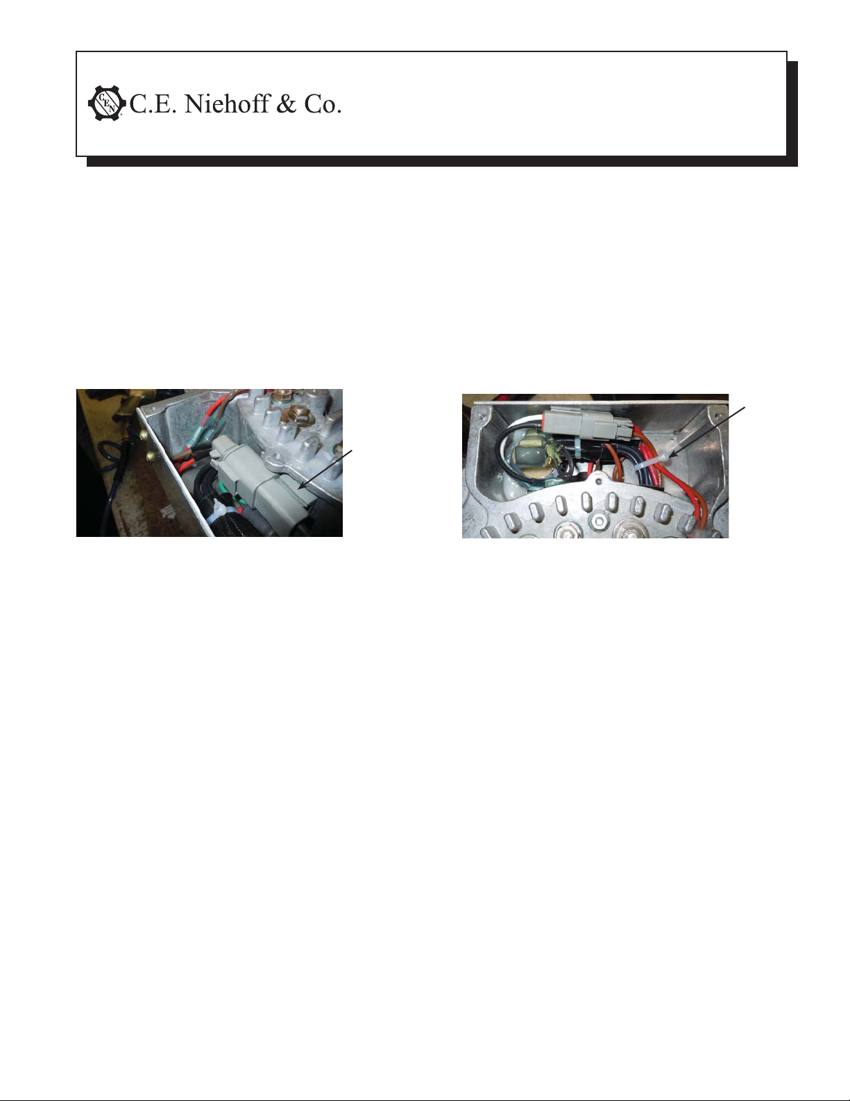
This kit contains a new wiring harness with a larger-sized connector assembly than what it
may be replacing. Remove front cover of control unit.
If gray fi eld connector
is attached
to the housing with a clip:
Clip
Figure 1 — Gray Field Connector Attached to
Housing with Clip
START ON
If gray fi eld connector
is secured
with wire ties only:
Wire
tie
Figure 2 — Gray Field Connector Secured with
Wire Ties Only
START ON
Page 1 of 3
PAGE 2
These instructions should be used in place of
harness replacement instructions
in 700 Series Service Manual SM7
PAGE 3
II169B
Page 2
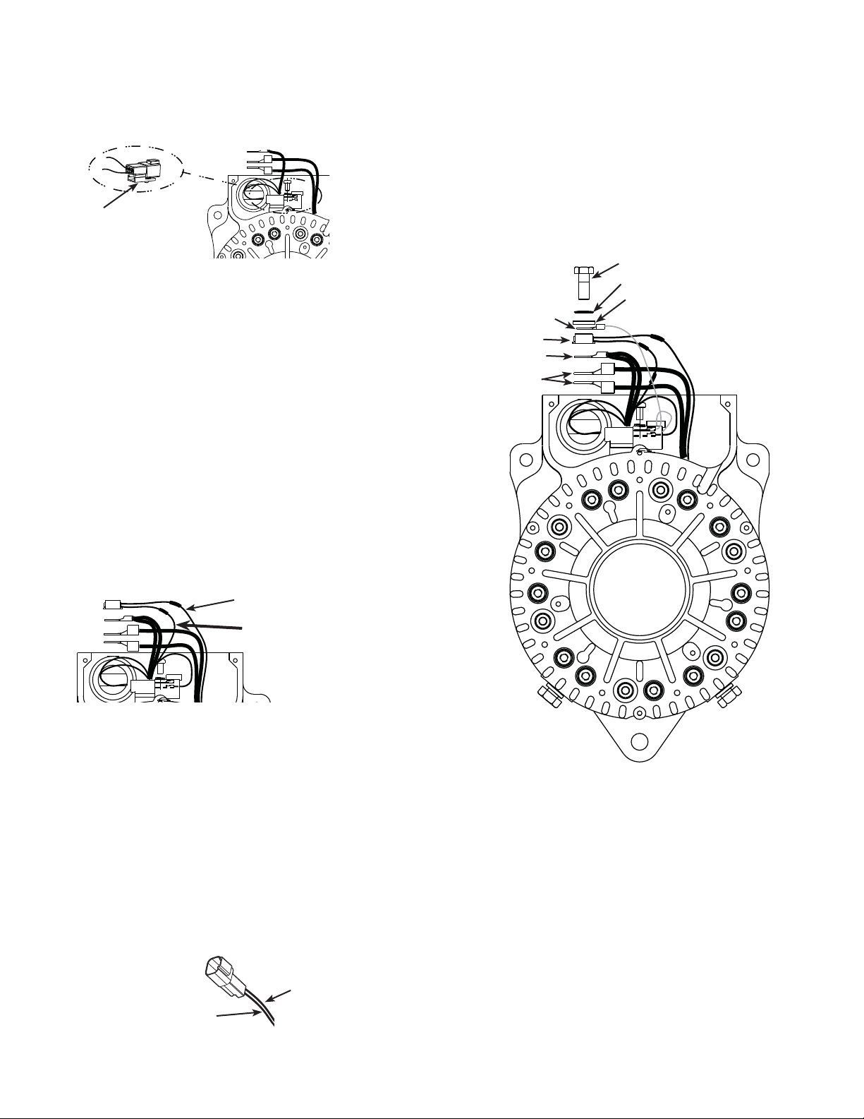
If the gray fi eld connector is attached with clip...
1. Disconnect existing wiring harness terminals:
a. Slide existing field connector holder from clip.
Connector holder
Figure 3 — Disconnecting Field Connector
b. Remove black and white wires from female
end and discard parts of female end of
connector. Do not remove pins from ends of
black and white wires.
c. Disconnect internal B+ connection, saving
hardware for reassembly.
d. Disconnect two green wires from housing.
Save hardware for reassembly.
e. Disconnect existing wiring harness from
thermal switch (see Figure 4):
1) Cut brown wire from existing harness to
thermal switch, leaving enough length
from thermal switch for reassembly, and
strip 1/4 inch of insulation.
2) Leave other brown wire to thermal switch
as-is for reassembly.
b. Slide assembled connector onto clip and make
sure it is secure.
c. Use new male end provided in kit only if needed.
6. Using splice and sleeves from kit: crimp, solder,
and insulate brown wire from new harness to existing brown wire from thermal switch.
7. Reassemble internal B+ connection and hardware
as shown in Figure 6.
Hex bolt—torque to 27-28.5 Nm/20-21 lb.ft.
Disc spring washer
Red wire terminal
from capacitor
Thermal switch
Red wires terminal
from harness
Rectifi er terminals
Flat washer
Leave this wire alone
See step 1e
Figure 4 — Thermal Switch Wiring
2. Remove existing wiring harness from housing,
taking the grommet out as well. Discard harness
and grommet.
3. Install wiring harness into notch in plate, making
sure grommet is securely wedged in notch.
4. Reconnect green ground wire and green wire in
housing, Torque screw and lockwasher to 3.4 Nm/
45 lb. in.
5. Re-assemble gray field connector:
a. Assemble new female connector end onto
black and white wires of new harness as
shown in Figure 5.
FEMALE END
White wire
Figure 6 — Internal B+ Stacking Order
Figure 5 — Field Coil Connector Assembly
Page 2 of 3
Black wire
II169B
Page 3

If the gray fi eld connector is secured with wire ties only...
1. Clip wire ties inside control unit.
2. Disconnect existing wiring harness terminals:
a. Remove black and white wires from female
end and discard parts of female end of
connector. Do not remove pins from ends of
black and white wires.
c. Disconnect internal B+ connection, saving
hardware for reassembly.
d. Disconnect green ground wire from housing.
Save hardware for reassembly.
e. Cut red wire from diode trio in housing and
use sleeving to insulate. It will not need to be
reattached to new harness. See Figure 7.
f. Disconnect existing wiring harness from
thermal switch (see Figure 7):
1) Cut brown wire from existing harness to
thermal switch, leaving enough length
from thermal switch for reassembly, and
strip 1/4 inch of insulation.
2) Leave other brown wire to thermal switch
as-is for reassembly.
Leave this wire alone
7. Using splice and sleeves from kit: crimp, solder,
and insulate brown wire from new harness to existing brown wire from thermal switch.
8. Reassemble internal B+ connection and hardware as shown in Figure 9.
9. Attach new wire ties to firmly secure connector
and other wires inside control unit.
Hex bolt—torque to 27-28.5 Nm/20-21 lb.ft.
Disc spring washer
Flat washer
Thermal switch
Red wires terminal
from harness
Rectifi er terminals
See step 2e
See step 2f
Figure 7 — Existing Harness Wiring
3. Remove existing wiring harness from housing,
taking the grommet out as well. Discard harness
and grommet.
4. Install wiring harness into notch in plate, making
sure grommet is securely wedged in notch.
5. Reconnect green ground wire in housing, Torque
screw and lockwasher to 3.4 Nm/ 45 lb. in.
6. Re-assemble new gray field connector:
a. Assemble new female connector end onto
black and white wires of new harness as
shown in Figure 8.
b. Save new male end of gray field coil connector
provided in kit to replace existing male end of
connector connecting field coil leads from shell.
FEMALE END
White wire
Figure 9 — Internal B+ Stacking Order
Black wire
Figure 8 — Field Coil Connector Assembly
C. E. Niehoff & Co. • 2021 Lee Street • Evanston, IL 60202 Tech Services Hotline 800-643-4633
II169B
Page 3 of 3
 Loading...