

Page 1
C626 Alternator
Installation Instructions
This symbol is used to indicate presence
CAUTION
of hazards that can cause minor property
damage.
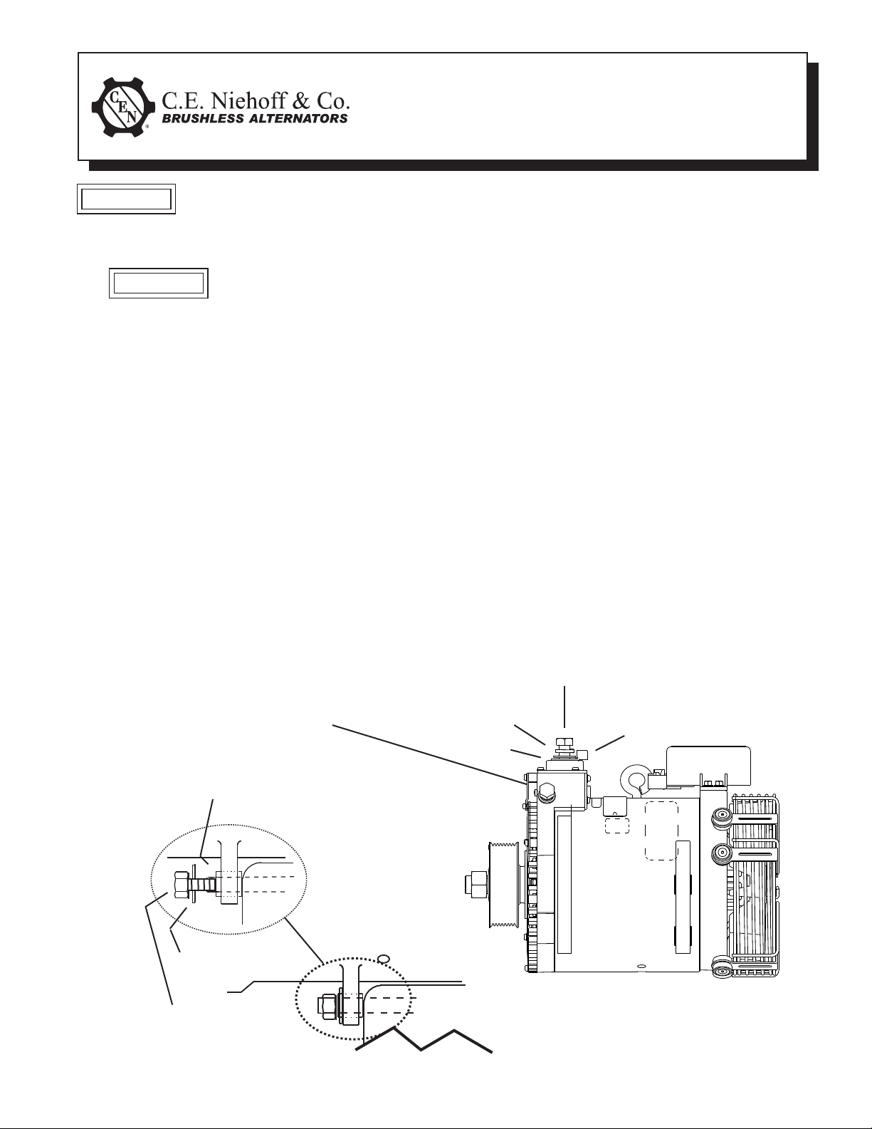
1. Install alternator as shown in Figure 1:
Both slip bushings located in rear
modified mounting foot must be
securely tightened against
alternator mounting bracket
on engine. Failure to do so
can result in broken mounting
feet or broken mounting bracket.
a. Use hardened washers between aluminum
b. OEM units are shipped with pulley, disc
c. Aftermarket units are shipped with shaft
d. Follow vehicle manufacturer’s recommen-
2. All cabling, wiring or conduit must be supported
CAUTION
surfaces and bolt heads and nuts.
spring washer and locknut installed.
collar, disk spring washer, and nut. Remove
and discard shaft collar. Install pulley and
furnished disk spring washer. Torque nut to
163 Nm/ 120 lb. ft.
dations for belt tension.
within 305 mm/12 in. of termination on alternator.
3. Choose wire gauge capable of handling maximum alternator output with no more than 0.4 V
drop on each leg from alternator to battery.
4. Regulator is furnished with OEM units and is
supplied separately by request with aftermarket
units. Mounting screws on regulator should be
torqued to 8.5 Nm/75 lb. in. A2-337 regulator:
See page 2 for regulator mounting instructions.
5.
Make electrical connections to CEN regulator as
required, using proper ring terminals (follow vehicle
manufacturer’s diagram and separate instructions
packed with extended wiring harness when used):
a. Make sure alternator-to-regulator harness
is plugged securely in regulator receptacle.
b. A2-141 regulators have an M6 stud P termi-
nal and an M5 stud D+ terminal. Torque
terminal nuts with disc spring washers to
4.5 Nm/40 lb. in.
• P terminal taps AC voltage, typically half the
charge voltage.
• D+ terminal provides 28 VDC voltage out put to multiplex controller. When connecting
D+ terminal to controller through a relay,
the relay coil must be diode protected and
rated for proper voltage.
c. A2-337 regulator: See page 2 for regulator
electrical connections.
Alternator B- M10x1.5 bolt,
lockwasher and washer—
torque to 15 Nm/11 lb. ft.
Slip bushing must be tightened against
bracket — see “CAUTION” above
Hardened washer
M12/0.50 bolt and washer –
torque to 81 Nm/60 lb. ft.
Figure 1 - C626 Alternator Installation Details
Page 1 of 2
Lockwasher
Bracket
on engine
Alternator B+ M12x1.75 bolt–torque to 32 Nm/23.5 lb. ft.
Battery output cable terminal
Washer
II172A
Page 2
A2-337 Regulator Installation and Electrical Connection:
1. Install regulator on alternator, using mounting
hardware furnished with regulator. Torque
screws to 8.5 Nm/75 lb. in.
2. Plug alternator-to-regulator harness securely into
regulator.
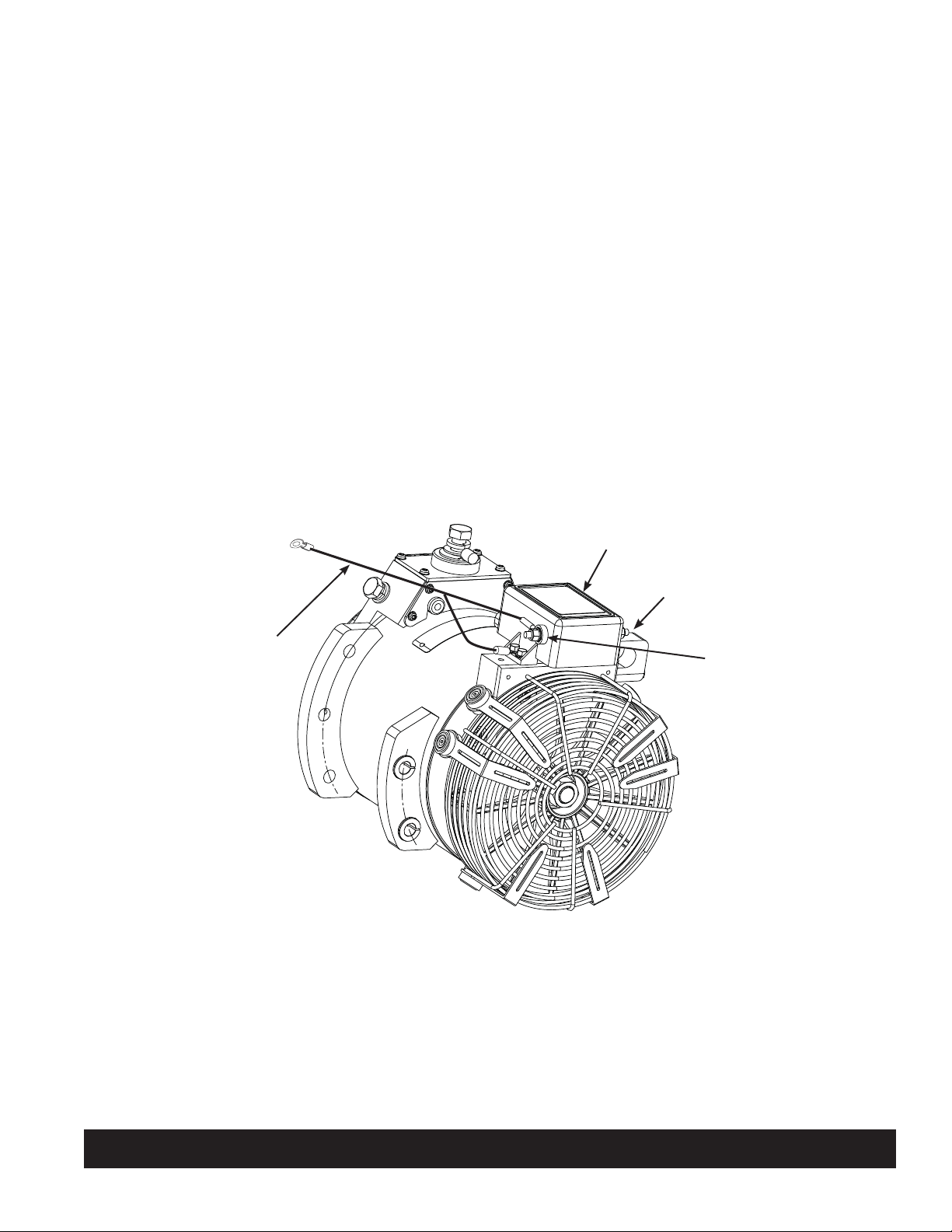
3. If A9-4011 temperature sense lead is used, see
Figure 2:
a) Connect twin lead ends of A9-4011 tempera ture sense lead:
• one to regulator T terminal, using hard ware furnished, torque terminal nut to
4.5 Nm/40 lb. in.
• the other to one mounting bolt. Retorque
to 8.5 Nm/75 lb. in.
b) Connect single sense lead ring terminal to
B– terminal on battery as shown in Figure 2.
Tighten hardware securely.
c) Coil up any unused sense lead and use cable
ties every 12-14 inches to securely support
temperature sense lead between regulator
and battery.
Connect to B– terminal on battery
4. Complete remaining connections to regulator, if
required, as shown in Figure 2.
• Connect P terminal to tachometer or relay.
P terminal taps AC voltage, typically half the
charge voltage. Torque M6 terminal nut on
regulator to 4.5 Nm/ 40 lb. in.
• Connect D+ terminal to multiplex controller:
D+ terminal provides 28 VDC voltage output
to multiplex controller. When connecting D+
terminal to controller through a relay, the
relay coil must be diode protected and rated
for proper voltage. Torque M5 terminal nut
on regulator to 4.5 Nm/40 lb. in.
5. When the A9-4011 temperature sense lead is not
in use, the regulator will operate at 27.5 V.
6. When A9-4011 temperature sense lead is in use,
the lead senses the ambient temperature within
the battery box and regulator will adjust charge
voltage based on battery temperature—the higher
the battery temperature, the lower the charge
voltage.
D+ terminal – torque M5 nut to 4.5 Nm/40 lb. in.
A9-401 1 Temperature
sense lead
Figure 2 – A2-337 Regulator on C626 Alternator with Temperature Sense Lead
P terminal – torque M6 nut
to 4.5 Nm/40 lb. in.
T terminal – torque M6 nut
to 4.5 Nm/40 lb. in.
C. E. Niehoff & Co. • 2021 Lee Street • Evanston, IL 60202 Tech Services Hotline 800-643-4633
Page 2 of 2
II172A
 Loading...