

Page 1

C540 Alternator
1.
Install alternator on pad mount per vehicle manufacturer’s instructions, including hardware specifications and torque.
2. Units are shipped with shaft collar, Belleville
washer and nut. Remove and discard shaft collar.
Install pulley and furnished Belleville washer.
Torque nut to 135 Nm/ 100 lb. ft.
C540 Alternator
with Regulator
and External Rectifi er
Installation Instructions
Nut–
torque to
135 Nm/100 lb.ft.
Belleville
washer
Figure 1 - C540 Alternator Installation
External Rectifier and Bracket
1. Mounting location of rectifier and bracket should
provide proper cooling and protect rectifier from
direct water, road debris, or chemicals.
Rectifier can be mounted up to 6 feet away from
alternator. Harnesses cannot be strung together
to create different lengths.
2. Use hardened washers between aluminum
surfaces and bolt heads and nuts. Bracket
mounting bolts must have minimum .50 in.
thread engagement. See Figure 2 for torque
values.
3. Use a suitable adhesive such as Loctite
or equivalent on screws. Follow manufacturer’s
instructions.
®
222
Flat washer
Lockwasher
.3750-16 UNC-2B Mounting bolt
grade 5 or better–
torque to 27 Nm/20 lb.ft.
Figure 2 - Rectifi er and Bracket Installation
(4 places) –
torque to
54 Nm/40 lb.ft.
11mm/0.44 in.
Mounting bolt - grade
5 or better
Lockwasher
Flat washer
Locknut
Regulator
1. Mounting location of regulator must provide
protection from water, road debris, or chemicals.
Regulator can be located up to 18 inches away
from the rectifier. If extension harness CEN
A9-448 is added, the regulator can be moved an
additional 43 in. away.
2. See Figure 3 for torque values.
Page 1 of 2
#10-32 x .62 fl ange lock screw (4 places) -
torque to 8.5 Nm/75 lb. in.
Figure 3 - Regulator Installation
II176A
Page 2
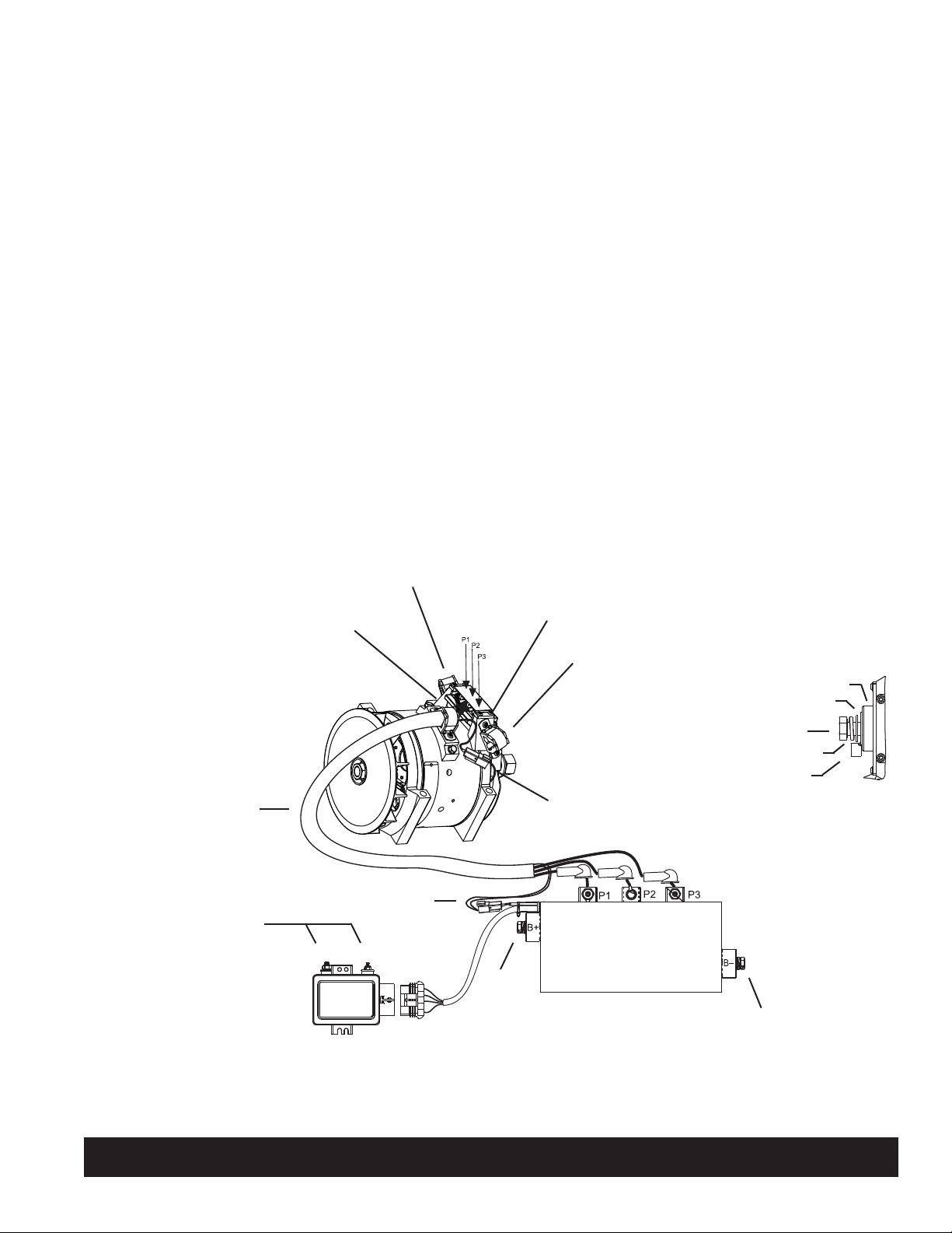
Wiring Connections
1. Connect alternator phase cable into terminal
block on top of alternator:
a) Run phase cable through cable bracket
mounted in one of three locations (LOC. A, B,
or C). See Figure 4.
b) Torque screws to 9 Nm/80 lb. in. to fasten
cables to terminal block.
c) Coat terminals with Dow Corning®1-2577
Low VOC RTV coating or equivalent. Do not
use coating containing acetic acid (vinegar
smell) on electrical components.
2. Connect remaining harnesses between components as shown in Figure 4. Use torque values
shown.
3. Choose wire gauge for B+ and B– cables capable
of handling maximum alternator output with
minimum voltage drop.
4. Connect IGN terminal on regulator to ignition
source through oil pressure switch, using #10
ring terminal. Torque #10-24 terminal nut to
3.4 Nm/30 lb. in.
5. If required, connect P terminal to tachometer or
relay, using 1/4 in. ring terminal. Torque terminal nut to 3.4 Nm/30 lb.in.
Sealing Wiring Connections
1. On ALL metallic electrical connections to rectifier
(including B+ and B– connections), alternator,
regulator, and their harness connectors, apply
Dow Corning® 1-2577 Low VOC RTV coating or
equivalent. Do not use coating containing acetic
acid (vinegar smell) on electrical components.
2. At regulator harness connections, apply coating as
described in step 1, then wrap connection in
electrical tape from sleeve to sleeve.
Phase
cable
P and IGN
terminal nuts –
torque to
3.4 Nm/30 lb. in.
Cable bracket
LOC. B
Cable bracket
LOC. A
Field inline connection
P
IGN
inset above)
B+
(see
Screws –
torque to 6.7 Nm/60 lb. in.
Cable bracket
LOC. C
Field
inline
connection
Insulator
Washer
B+ terminal bolt –
torque to 30 Nm/22 lb. ft.
Lockwasher
Battery output cable terminal
B+ Terminal Connection
Phase terminal bolts (3 places) –
torque to 8 Nm/70 lb. in.
B– terminal bolt –
torque to 30 Nm/22 lb. ft.
Figure 4 - Electrical Connections
C. E. Niehoff & Co. • 2021 Lee Street • Evanston, IL 60202 Tech Services Hotline 800-643-4633
Page 2 of 2
II176A
 Loading...