

Page 1
500 Series Troubleshooting Guide
for C520 Alternators
Hazard Defi nitions
These terms are used to bring attention to presence of hazards of
various risk levels or to important information concerning product
life.
Indicates presence of hazards that
CAUTION
will or can cause minor personal
injury or property damage if
ignored.
Indicates special instructions on
NOTICE
installation, operation or mainte nance that are important but not
related to personal injury hazards.
Table of Contents
Section 1: Wiring .......................................................... 2
Section 2: CAN/J1939 Diagnostics ............................... 3
Section 3: Basic Troubleshooting ................................. 4
Section 4: Advanced Troubleshooting ....................... 5-6
Battery Conditions
Until temperatures of electrical
NOTICE
system components stabilize, these
conditions may be observed during
cold start voltage tests.
• Maintenance or low maintenance battery:
— Immediately after engine starts, system volts are
lower than regulator setpoint with medium amps.
— 3-5 Minutes into charge cycle, system volts are
higher and amps are dropping.
— 5-10 Minutes into charge cycle, system volts are
at, or nearly at, regulator setpoint and amps are
reduced to a minimum.
— Low maintenance battery has same characteris tics with slightly longer recharge times.
• Maintenance-free battery:
— Immediately after engine start, system volts
are lower than regulator setpoint with low
charging amps.
— 15-30 minutes into charge cycle, volts and amps
are still low.
— 15-30 minutes into charge cycle, volts increase
several tenths. Amps increase gradually, then
quickly, to medium to high amps.
— 20-35 minutes into charge cycle, volts increase
to setpoint and amps decrease.
• High-cycle maintenance-free battery:
— These batteries respond better than standard
maintenance-free. Charge acceptance of these
batteries may display characteristics similar to
maintenance batteries.
Charge Volt and Amp Values
The volt and amp levels are a function of the battery state
of charge. If batteries are in a state of discharge, as after
extended cranking time to start the engine, the system
volts, when measured after the engine is started will be
lower than the regulator setpoint and the system amps
will be high. This is a normal condition for the charging
system. The measured values of system volts and amps
will depend on the level of battery discharge. In other
words, the greater the battery discharge level, the lower
the system volts and higher the system amps will be.
The volt and amp readings will change, system volts
reading will increase up to regulator setpoint and the
system amps will decrease to low level (depending on
other loads) as the batteries recover and become
fully charged.
• Low Amps: A minimum or lowest charging system
amp value required to maintain battery state of
charge, obtained when testing the charging system
with a fully charged battery and no other loads applied. This value will vary with battery type.
• Medium Amps: A system amps value which can
cause the battery temperature to rise above the adequate charging temperature within 4-8 hours of
charge time. To prevent battery damage, the charge
amps should be reduced when battery temperature
rises. Check battery manufacturer’s recommendations for proper rates of charge amps.
• High Amps: A system amps value which can cause
the battery temperature to rise above adequate charging temperature within 2-3 hours. To prevent battery
damage, the charge amps should be reduced when
the battery temperature rises. Check battery manufacturer’s recommendations for proper rates
of charge amps.
• Battery Voltage: Steady-state voltage value as mea-
sured with battery in open circuit with no battery
load. This value relates to battery state of charge.
• Charge Voltage: A voltage value obtained when the
charging system is operating. This value will be higher than battery voltage and must never exceed the
regulator voltage setpoint.
• B+ Voltage: A voltage value obtained when measur-
ing voltage at battery positive terminal or alternator
B+ terminal.
• Surface Charge: A higher than normal battery volt-
age occurring when the battery is removed from a
battery charger. The surface charge must be removed
to determine true battery voltage and state of charge.
• Significant Magnetism: A change in the strength or
intensity of a magnetic field present in the alternator
rotor shaft when the field coil is energized. The magnetic field strength when the field coil is energized
should feel stronger than when the field is not energized.
• Voltage Droop or Sag: A normal condition which
occurs when the load demand on the alternator is
greater than rated alternator output at given rotor
shaft RPM.
TG0048A
Page 1
Page 2
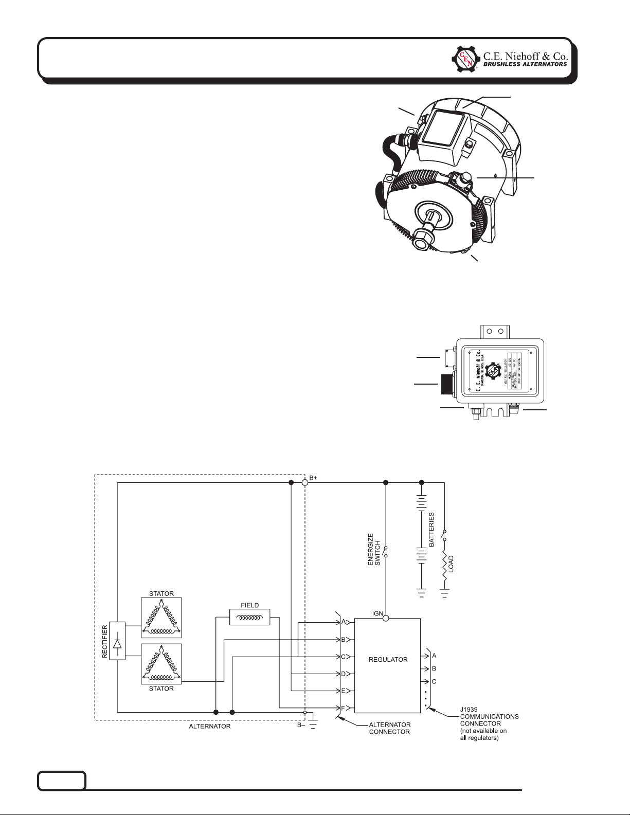
Section 1: Wiring Diagram
CEN C520 Alternator Description and
Operation
C520 14 V 300 A 3-phase alternator is internally
rectified. All windings and current-conducting components are non-moving, so there are no brushes or slip
rings to wear out.
After engine is running, regulator receives energize
signal. Regulator monitors alternator rotation and
provides field current only when it detects alternator
shaft rotating at or above idle speed.
After regulator detects alternator rotation, it gradually
applies field current, preventing an abrupt mechanical load on accessory drive system. The soft start may
take up to 20 seconds.
A2-215 regulator used with some of these units is flat
temperature compensated. A 15.5 V regulator setpoint
is available for battery isolator applications.
A2-326 regulator used with some of these units includes measurement of battery current, voltage, and
temperature for adjustment of regulator setpoint.
IGN terminal
T
Figure 1 — C520 Alternator/A2-215 Regulator Features
J1939 receptacle
Regulator receptacle
IGN terminal
T
T
T
B– terminal
T
T
T
LED
T
B+
terminal
LED
Figure 2 — A2-326 Remote-Mounted Regulator Features
Page 2
Figure 3 — C520 Alternator with Regulator
TG0048A
Page 3
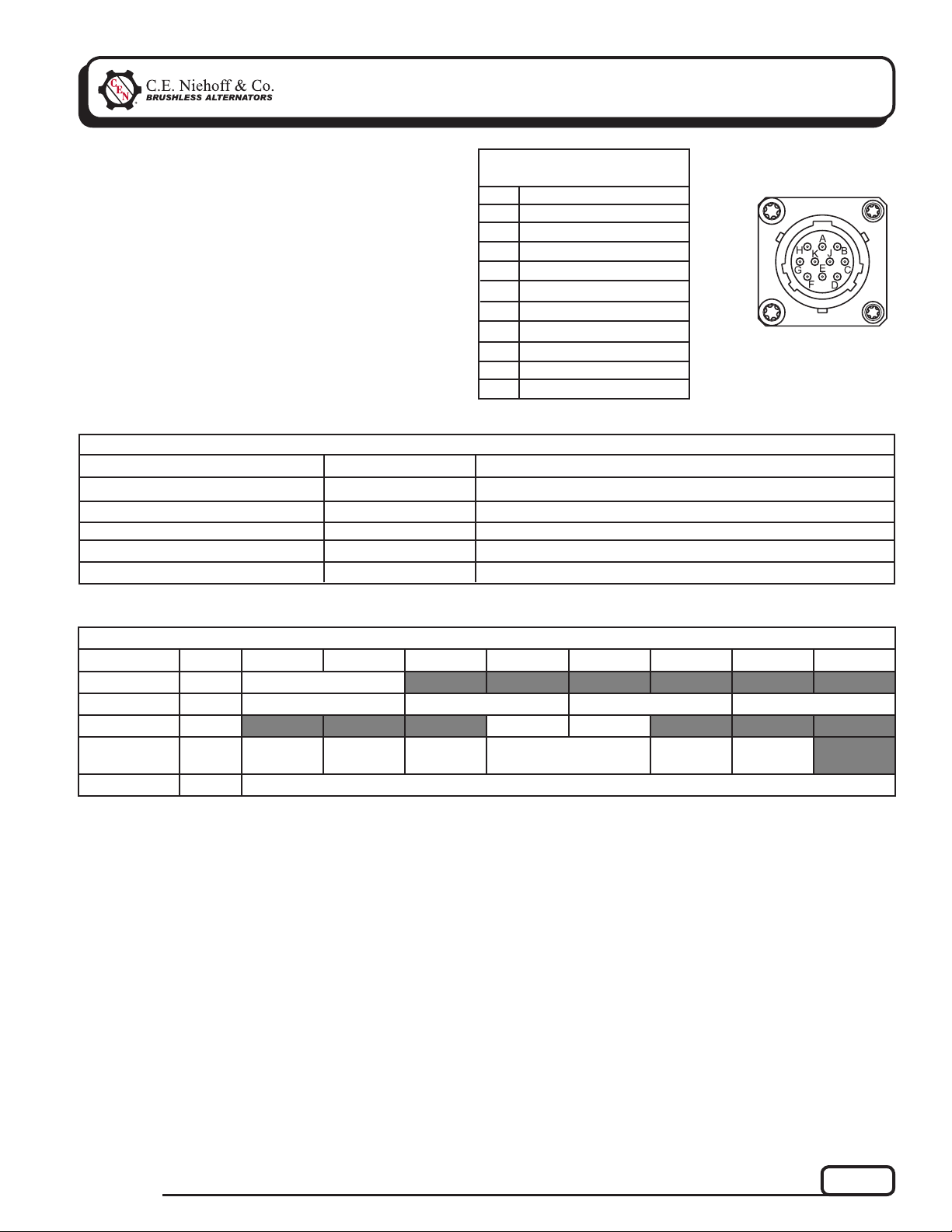
Section 2: CAN/J1939 Diagnostics
CAN/J1939 Interface
DESCRIPTION AND OPERATION
The CEN A2-326 digital regulator is compatible with
SAE J1939 communications standard for vehicle networking.
CEN uses MIL-STD connector MS3112E12-10P to interface between the A2-326 and the vehicle J1939 databus.
Mating connector is MS3116E12-10S or equivalent.
If J1939 connection is not used, the 10-pin connector
must be covered with connector cover MS3181-12CA or
equivalent. Message content is shown in Table 2.
TABLE 2 – A2-326 Regulator/J1939 Readout Diagnostics (see Table 3)
Regulator Readout
Alternator Output Voltage 28 V System
Alternator Speed
Regulator Temperature
Alternator Output
Charging System Hours
Expected Reading
13–15 V
1200 to 8000 RPM
Less than 257 F/125ºC
0–100%
>0 hours
TABLE 1 – J1939 Connector
Circuit Identifi cation
Pin
A
B
C
D
E
F
G
H
J
K
Identifi cation
CANH
CANL
CAN SHIELD
Battery
Mfr use only
Mfr use only
Mfr use only
Temperature sensor
Voltage sensor
Current sensor
Figure 4 – J1939
Connector Pins
Action—If Expected Reading Not Present
See Chart 1, page 6.
Check drive belt and charging system connections.
Decrease load on alternator.
Varies with load.
Check drive belt and charging system connections.
TABLE 3 – Message Data
PGN Name PGN Byte 1 Byte 2 Byte 3 Byte 4 Byte 5 Byte 6 Byte 7 Byte 8
ALT RPM
ALT VOLT
ALT TEMP
PROPRIETARY #1
PROPRIETARY #2
0xFED5 ALT RPM
0xFEF7 VOLT SETPOINT ALT VOLT REG IGN VOLT BATT VOLT
0xFEA7 REG TEMP BATT TEMP
0xFFC8 BATT
CURRENT
0xFFC9 Proprietary Content: For Manufacturer Test Only
SHUTDOWN
COUNT
BATT AGE HOUR METER MINUTES
(0-59)
ALT LOAD
TG0048A
Page 3
Page 4

Section 3: Basic Troubleshooting
A. Tools and Equipment for Job
• Digital Multimeter (DMM)
• Ammeter (digital, inductive)
• Jumper wires
If no tools are available, monitor LED code.
B. Identifi cation Record
List the following for proper troubleshooting:
Alternator model number ______________________
T
Regulator model number ______________________
T
TABLE 4 – System Conditions
SYMPTOM
Low Voltage Output
High Voltage Output
No Voltage Output
Check: loose drive belt; low bat-
tery state of charge.
Check: current load on system
is greater than alternator
can produce.
Check: defective wiring or poor
ground path.
Check: defective alternator
and/or regulator.
Check: defective regulator.
Check: alternator.
Check: presence of energize sig-
nal to IGN terminal on regula-
tor.
Check: battery voltage at alter-
nator output terminal.
Check: defective alternator
and/or regulator.
ACTION
C. Basic Troubleshooting
1. Inspect charging system components
Check connections at ground cables, positive
cables, and regulator harness. Repair or replace
any damaged component before troubleshooting.
2. Inspect connections of vehicle batteries
Connections must be clean and tight.
3. Determine battery type, voltage, and state
of charge
Batteries must be all the same type for system
operation. If batteries are discharged, recharge
or replace batteries as necessary. Electrical
system cannot be properly tested unless batter ies are charged 95% or higher. See page 1 for
details.
4. Connect meters to alternator
Connect red lead of DMM to alternator B+
terminal and black lead to alternator B–
terminal. Clamp inductive ammeter on B+
cable.
5. Operate vehicle
Observe charge voltage.
If charge voltage is above
33 volts, immediately shut
down system. Electrical
system damage may occur
if charging system is
allowed to operate at
excessive voltage. Go to
Table 4 at left.
If voltage is at or below regulator setpoint, let
charging system operate for several minutes to
normalize operating temperature.
6. Observe charge volts and amps
Charge voltage should increase and charge amps
should decrease. If charge voltage does not in-
crease within ten minutes, continue to next step.
CAUTION
Page 4
7. Batteries are considered fully charged if charge
voltage is at regulator setpoint and charge amps
remain at lowest value for 10 minutes.
8. If charging system is not performing properly,
go to Chart 1, page 6.
TG0048A
Page 5

Section 4: Advanced Troubleshooting
A2-215 and A2-326 Regulators
DESCRIPTION AND OPERATION
A2-215 regulator is attached directly to the outside of
the alternator. A2-326 regulator is remotely mounted
from extended wiring harnesses.
Main diagnostic feature of A2-215 regulator is green
lens LED. The LED indicates field coil performance.
See Table 5 for diagnostic features and LED explanations.
Main diagnostic feature of A2-326 regulator consists
of a tricolored (green, amber, red) LED located on the
side of the regulator. The LED works like a voltmeter,
measuring charging voltage. See Table 6 for diagnostic
features and LED explanations.
TABLE 5 – A2-215 Regulator Diagnostics
LED CONDITION
GREEN On steady
GREEN Flashing
CLEAR LED off
Field on full.
Speed of LED flashing determines alternator
output.
Field off.
STATUS
TROUBLESHOOTING A2-326 REGULATOR
Shut down vehicle and restart engine. If alternator
functions normally after restart, a “no output condition” was normal response of voltage regulator to
overvoltage condition. Inspect condition of electrical
system.
If you have reset alternator once, and electrical system
returns to normal charge voltage condition, there may
have been a one time, overvoltage spike that caused
OVCO circuit to trip.
If OVCO circuit repeats cutout a second time in short
succession and shuts off alternator F+ circuit, try
third restart. If OVCO circuit repeats cutout a third
time, check color of LED while engine is running.
ACTION
No action required.
Check drive belt, moderate RPM if necessary.
Check condition of field circuit.
LED COLOR
GREEN Flashing*
AMBER Flashing *
RED Flashing*
Steady
CLEAR LED off
Alternator and regulator operating normally.
Energize signal present, alternator not rotat-
If alternator is rotating: System voltage lower
System voltage higher than setpoint.
OVCO tripped.
Energize circuit fault.
* Flashing occurs twice per second.
TG0048A
TABLE 6 – A2-326 Regulator Diagnostics
STATUS
ing or alternator speed too low for cut-in.
than setpoint – electrical load exceeds alternator rating at present rotor speed.
ACTION
No action required.
Check drive belt, increase RPM.
When loads decrease or speed increases, LED
should flash GREEN. If not, check drive belt
and charging system connections.
May occur during normal load switching.
Overvoltage condition. Attempt reset. System diag-
nosis required.
Check for system voltage at IGN terminal on
regulator. If OK, replace regulator. If not OK,
check vehicle wiring and ignition circuit.
Page 5
Page 6

Section 4: Advanced Troubleshooting
(CONT’D)
Chart 1 – No Alternator Output – Quick Diagnostic
Remote-mounted regulator applications: Check condition of fuse in wiring harness
before troubleshooting.
With engine running: Does battery voltage exist at alternator B+ terminal and regulator E terminal?
Yes
Repair vehicle harness circuit to E terminal on regulator
or B+ terminal on alternator.
T
With key off, engine off: Does battery voltage exist at alternator B+ terminal?
Yes
Repair vehicle harness circuit to B+ terminal on alternator.
T
With key off, engine off: Unplug alternator-to-regulator harness. Connect DMM on DC volt scale across
pins A and D, and then across pins C and E in harness plug. Does battery voltage exist for both pairs?
Yes
Alternator is defective.
T
With DMM on resistance scale, does the field resistance between pin F in harness plug and alternatorB– terminal measure about 1.6 (±0.2) ohms?
Yes
Alternator is defective.
T
Set DMM to diode test.
Check negative diodes: Connect red lead to pin B in harness plug. Connect black lead to alternator B– terminal. Meter should read OL (over limit). Reverse leads. Meter should read voltage drop.
Check positive diodes: Connect red lead to pin B in harness plug. Connect black lead to alternator B+ terminal. Meter should read voltage drop. Reverse leads. Meter should read OL (over limit).
Yes
Alternator is defective.
T
Momentarily (1 sec.) jumper pin F in harness plug to alternator B+ terminal. Touch shaft with steel tool to detect significant
magnetism. Is shaft magnetized?
Yes
T
Regulator is defective.
Alternator is defective.
No
T
No
T
No
T
No
T
No
T
No
T
Page 6
PIN CONNECTIONS
Pin A GND/B–
Pin B AC
Pin C GND/B–
Pin D B+
Pin E B+
Pin F F+
Figure 5 – Alternator-to-Regulator Harness Plug
TG0048A
Page 7

Notes
TG0048A
Page 7
Page 8

Notes
If you have questions about your alternator or any of these test procedures, or if you need to locate a Factory Authorized Service Distributor, please contact us at:
TEL: 800.643.4633 USA and Canada • TEL: 847.866.6030 outside USA and Canada • FAX: 847.492.1242
Page 8
C. E. Niehoff & Co.• 2021 Lee Street • Evanston, IL 60202 USA
TG0048A
 Loading...