

Page 1
C.E. Niehoff & Co.
C510 and C540 Alternators
Troubleshooting Guide
Hazard Defi nitions
These terms are used to bring attention to presence of hazards of
various risk levels or to important information concerning product
life.
Indicates presence of hazards that
CAUTION
will or can cause minor personal
injury or property damage.
Indicates special instructions on
NOTICE
installation, operation or mainte nance that are important but not
related to personal injury hazards.
Table of Contents
Section A: C510 Wiring Diagrams ............................2
Section B: C540 Wiring Diagrams ............................3
Section C: Basic Troubleshooting .............................4
Section B: Advanced Troubleshooting ............... 5 – 7
Battery Conditions
Until temperatures of electrical
NOTICE
system components stabilize, these
conditions may be observed during
cold-start voltage tests.
• Maintenance/Low Maintenance Battery
— Immediately after engine starts, system volts are
lower than regulator setpoint, amps are medium.
— 3–5 minutes into charge cycle, system volts increase,
amps decrease.
— 5–10 minutes into charge cycle, system volts
increase to, or near, regulator setpoint and amps
decrease to a minimum.
— Low maintenance battery has same characteristics
with slightly longer recharge times.
• Maintenance-free Battery
— Immediately after engine starts, system volts are
lower than regulator setpoint, low charging amps.
— Once charge cycle begins, low volts and low amps
are still present.
— After alternator energizes, voltage will increase
several tenths. Amps will increase gradually, then
quickly, to medium to high amps.
— F i n a l l y , v o l t s w i l l i n c r e a s e t o s e t p o i n t a n d a m p s w i l l
decrease.
The time it takes to reach optimum voltage and amperage will vary with engine speed, load, and ambient
temperature.
• High-cycle Maintenance-free Battery
These batteries respond better than standard maintenance-free. Charge acceptance of these batteries may
display characteristics similar to maintenance batteries.
• AGM (Absorbed Glass Mat) Maintenance-free Batter y
These dry-cell batteries respond better than standard
maintenance-free. If battery state of charge drops to
75% or less, batteries should be recharged to 95% or
higher separately from the engine’s charging system to
avoid damaging charging system components and to
provide best overall performance. Charge acceptance of
these batteries may display
maintenance batteries.
characteristics similar to
Battery Charge Volt and Amp Values
Volt and amp levels fluctuate depending on the battery state
of charge. If batteries are in a state of discharge—as after
extended cranking time to start the engine—system volts
will measure lower than the regulator setpoint after the
engine is restarted and system amps will measure higher.
This is a normal condition for the charging system; the
greater the battery discharge level, the lower the system
volts and the higher the system amps. The volt and amp
readings will change as batteries recover and become fully
charged: system volts will increase to regulator setpoint
and system amps will decrease to low level (depending on
other loads).
• Low Amps: Minimum or lowest charging system amp
value required to maintain battery state of charge,
obtained when testing the charging system with a fully
charged battery and no other loads applied. This value
will vary with battery type.
• Medium Amps: System amps value which can cause
the battery temperature to rise above adequate charging
temperature within 4-8 hours of charge time. To prevent battery damage, the charge amps should be
reduced when battery temperature rises. Check battery
manufacturer’s recommendations for proper charge
amp rates.
• High Amps: System amps value which can cause
the battery temperature to rise above adequate charging
temperature within 2-3 hours of charge time. To prevent battery damage, the charge amps should be
reduced when battery temperature rises. Check battery
manufacturer’s recommendations for proper charge
amp rates.
• Battery Voltage: Steady-state voltage value as mea-
sured with battery in open circuit with no battery load.
This value relates to battery state of charge.
• Charge Voltage: Voltage value obtained when the
charging system is operating. This value will be higher
than battery voltage and must never exceed the regulator voltage setpoint.
• B+ Voltage: Voltage value obtained when measuring
voltage at battery positive terminal or alternator B+
terminal.
• Surface Charge: Higher than normal battery voltage
occurring when the battery is disconnected from
battery charger. The surface charge must be removed
to determine true battery voltage and state of charge.
• Significant Magnetism: Change in strength or inten-
sity of a magnetic field present in alternator rotor shaft
when the field coil is energized. The magnetic field
strength when the field coil is energized should feel
stronger than when the field is not energized.
• Voltage Droop or Sag: Normal condition occurring
when the load demand on alternator is greater than
rated alternator output at given rotor shaft RPM.
TG1B
Page 1
Page 2
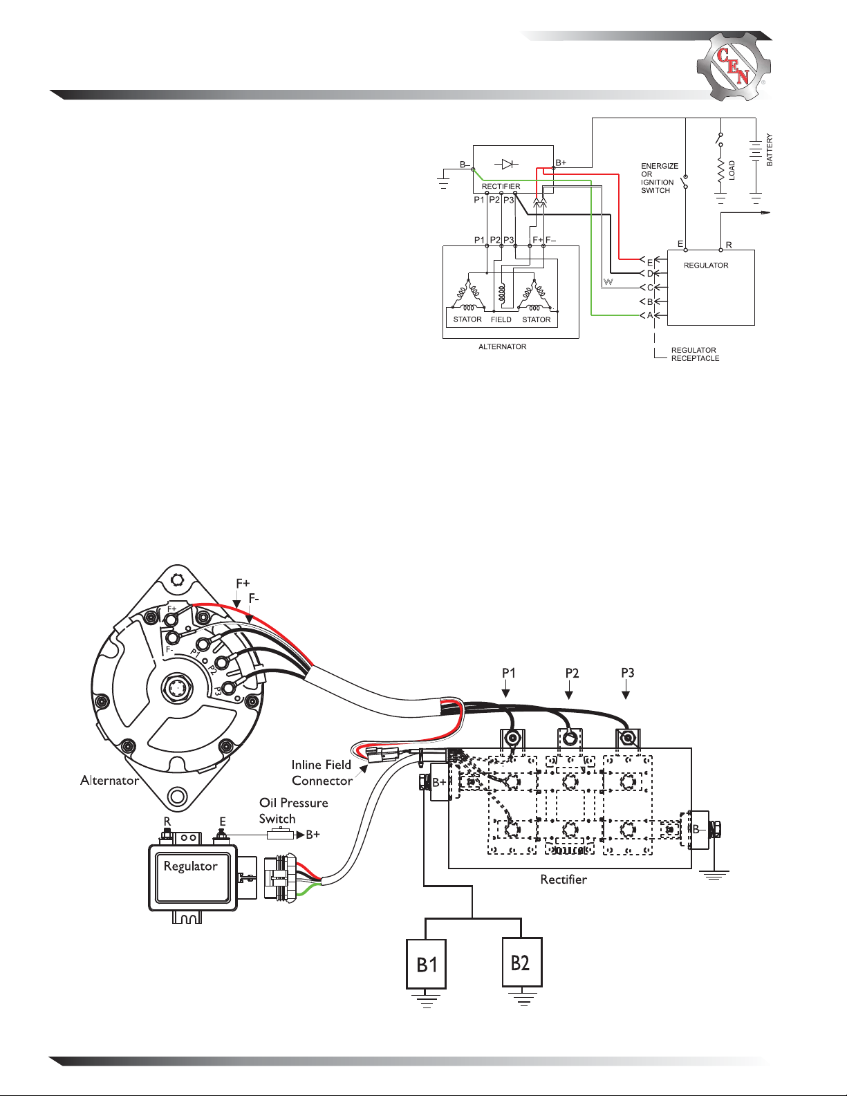
Section A: C510 Wiring Diagrams
CEN C510 Alternator
Description and Operation
C510 14 V (280 A) 3-phase brushless alternator uses an
externally mounted rectifier and regulator. All windings
and current-transmitting components are non-moving,
so there are no brushes or slip rings to wear out. This
unit is externally energized through an energize switch,
which activates regulator. Field coil is then energized.
Regulator maintains alternator output voltage at regulated setting as vehicle electrical loads are switched on
and off. Alternator output current is self-limiting and
will not exceed rated capacity of alternator.
A2-136 external regulator furnished with all units has
R terminal for optional AC voltage tap. Optional 15.5 V
regulator setpoint is available for battery isolator applications.
A8-201 or A8-205 external rectifier allows for mounting in engine compartment. A8-205 rectifier suppresses
electromagnetic interference (EMI) with internal filters
to acceptable levels defined by the Society of Automotive
Engineers (SAE) specification J1113/41. A8-205 rectifier
will not reduce EMI from sources such as antennas,
poor cable routing practice, or other electronic devices
that cause EMI. If EMI continues, consult an electromagnetic compliance (EMC) specialist to determine EMI
source.
R
BK
W
G
Figure 1 — C510 Wiring Diagram
Page 2
Figure 2 — C510 Terminal Locations
TG1B
Page 3
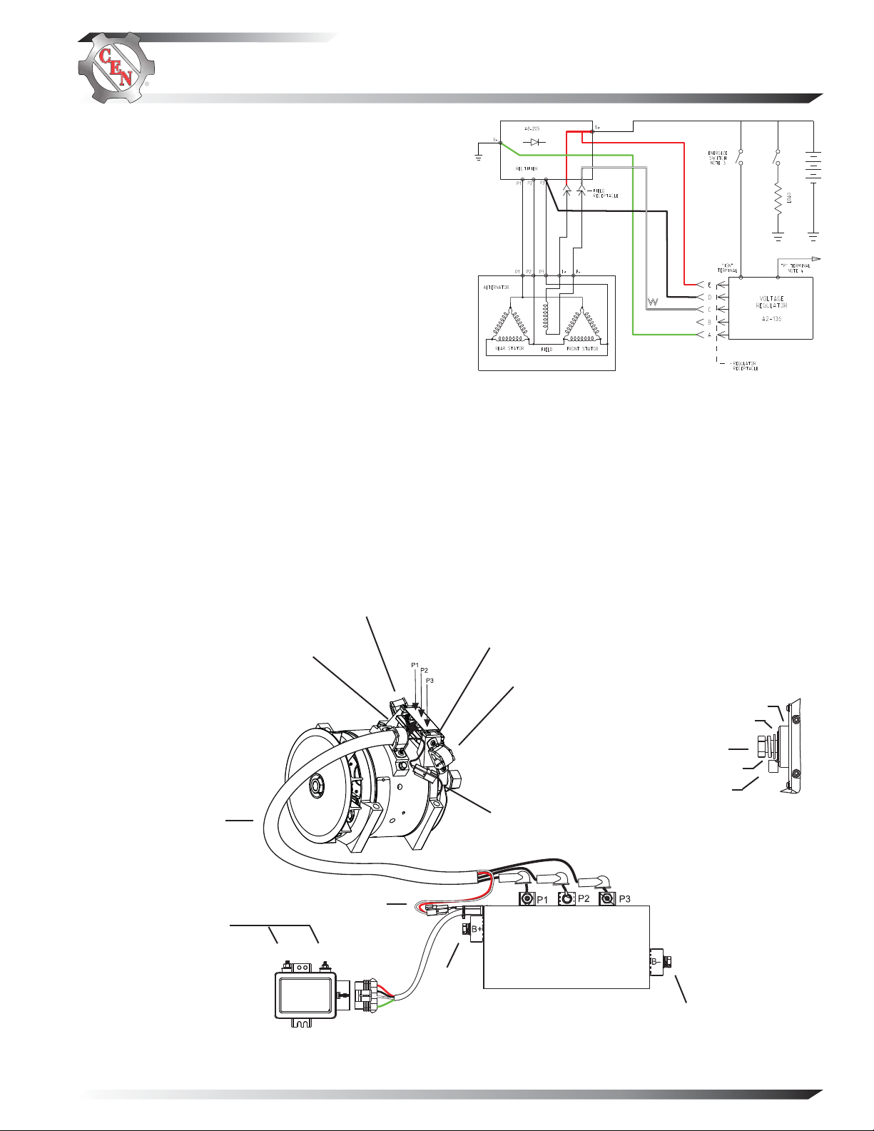
CEN C540 Alternator
Description and Operation
C540 14 V (300 A) 3-phase brushless alternator uses an
externally mounted rectifier and regulator. All windings
and current-transmitting components are non-moving,
so there are no brushes or slip rings to wear out. This
units is externally energized through an energize switch,
which activates regulator. Field coil is then energized.
Regulator maintains alternator output voltage at regulated setting as vehicle electrical loads are switched on
and off. Alternator output current is self-limiting and
will not exceed rated capacity of alternator.
A2-136 external regulator furnished with all units has
R terminal for optional AC voltage tap. Optional 15.5 V
regulator setpoint is available for battery isolator applications.
A8-205 external rectifier allows for mounting in engine
compartment. A8-205 rectifier suppresses electromagnetic interference (EMI) with internal filters to acceptable
levels defined by the Society of Automotive Engineers
(SAE) specification J1113/41. A8-205 rectifier will not
reduce EMI from sources such as antennas, poor cable
routing practice, or other electronic devices that cause
EMI. If EMI continues, consult an electromagnetic compliance (EMC) specialist to determine EMI source.
Section B: C540 Wiring Diagrams
R
BK
W
G
Figure 3 — C540 Wiring Diagram
Phase
cable
P and IGN terminal nuts –
torque to 3.4 Nm/30 lb. in.
Alternator
Regulator
Cable bracket
LOC. B
Cable bracket
LOC. A
Field inline connection
P
IGN
B+
(see
inset above)
Screws –
torque to 6.7 Nm/60 lb. in.
Cable bracket
LOC. C
Field
inline
connection
Rectifi er
Washer
B+ terminal bolt –
torque to 30 Nm/22 lb. ft.
Lockwasher
Battery output cable terminal
B+ Terminal Connection
Phase terminal bolts (3 places) –
torque to 8 Nm/70 lb. in.
B– terminal bolt –
torque to 30 Nm/22 lb. ft.
Insulator
TG1B
Figure 4 — C540 Terminal Locations
Page 3
Page 4

Section C: Basic Troubleshooting
Tools and Equipment for Job
• Digital Multimeter (DMM)
• Ammeter (digital, inductive
• CEN Regulator Bypass Adapter A10-129
• Jumper wire
Identifi cation Record
Alternator model number______________________
Rectifier model number _______________________
Regulator model number ______________________
Setpoints listed on regulator ___________________
Preliminary Check-out
Check symptoms in Table 1 and correct if necessary.
TABLE 1 – System Conditions
SYMPTOM ACTION
Low Voltage Output
High Voltage Output
No Voltage Output
Check: loose drive belt; low
battery state of charge.
Check: current load on system
is greater than alternator
can produce.
Check: defective wiring or poor
ground path; low regulator
setpoint.
Check: defective alternator, recti-
fier, or regulator.
Check: loss of phase winding. See
Chart 1, page 5.
Check: wrong regulator.
Check: high regulator setpoint.
Check: defective regulator.
Check: alternator.
Check: broken drive belt.
Check: battery voltage at alternator
output terminal.
Check: defective alternator, recti-
fier, and/or regulator.
Failure to check for the following
NOTICE
conditions will result in erroneous
test results in the troubleshooting
charts.
Basic Troubleshooting
1. Inspect charging system components for damage
Check connections at B– cable, B+ cable, rectifier
harness, and regulator harness. Also check connec tions at regulator terminal wiring from regulator to
veh icle components. Repa ir or replace any dama ged
component before electrical troubleshooting.
2. Inspect vehicle battery connections
Connections must be clean and tight.
3. Check drive belt
Repair or replace as necessary.
4. Determine battery voltage and state of charge
If batteries are discharged, recharge or replace
batteries as necessary. Electrical system cannot be
properly tested unless batteries are charged 95% or
higher.
5. Determine if battery isolator is used in
charging circuit
Check vehicle wiring diagram. If so, the isolator
must be jumpered out before troubleshooting. See
Chart 1 on page 5 for details.
6. Connect meters to alternator
Connect red lead of DM M to alternator B+ termina l
and black lead to alternator B– terminal. Clamp
inductive ammeter on B+ cable.
7. Operate vehicle
Observe charge voltage.
If charge voltage is above
16.5 volts, immediately shut
down system. Electrical
system damage may occur if
charging system is allowed to
operate at high voltage.
Go to Table 1.
If voltage is at or below regulator setpoint, let
charging system operate for several minutes to
normalize operating temperature.
8. Observe charge volts and amps
Charge voltage should increase and charge amps
should decrease. If charge voltage does not
increase within ten minutes, continue to next step.
9. Battery is considered fully charged if charge
voltage is at regulator setpoint and charge amps
remain at lowest value for 10 minutes.
10. If charging system is not performing properly,
CAUTION
go to Chart 1 on page 5.
Page 4
TG1B
Page 5

Section D: Advanced Troubleshooting
START HERE
Is there a battery isolator in the system?
Yes
Chart 1 – System Circuit
Install temporary jumper between one battery terminal and alternator terminal on isolator. Use minimum 12 AWG wire.
Do not operate charging system more than two
CAUTION
minutes with jumper installed. Charging system
voltage will be abnormally high and damage other
components.
For “low voltage output” condition: go to Chart 2 below.
For “no voltage output” condition: go to Chart 3, page 7.
Chart 2 – Low Voltage Output – Alternator Not Keeping Up with Load
No
Operate engine at idle, battery as sole load, no other loads applied. Measure charge voltage at battery posts
(B+ to B-) and output voltage at rectifier B+ and B– terminals. Measure charge amps entering battery and charge
amps out of alternator at rectifier B+ terminal.
Is difference in voltages greater than 0.2 V and amp difference less than 20 A?
Yes
No
Inspect harnesses and connections for corrosion.
Repair/replace as necessary. Repeat test.
Voltage value should be less than 0.1 V.
Increase engine speed to 1200 rpm, battery as sole load, no other loads
applied, meters attached as in box above. Increase load to 75, 150 and
280 A.
Does voltage remain steady?
Yes
No
Re-test charging system.
Measure AC voltage from terminals: P1 to P2, P2 to
P3, and P3 to P1 on rectifier.
Are voltages within 5% of each other?
Yes
No
Re-test charging system.
Start test at top of page 6.
TG1B
Page 5
Page 6

Section D: Advanced Troubleshooting (CONT’D)
Chart 2 – Low Voltage Output – Alternator Not Keeping Up with Load (cont’d)
RECTIFIER TEST
The following will test modules inside rectifier:
1. Disconnect all battery cables.
2. Disconnect harness leads to rectifier terminals P1, P2 and P3.
3. Disconnect B+ and B– cables from rectifier.
4. Unplug rectifier-to-regulator harness.
5. Unplug alternator field circuit harness connector.
6. Use DMM set to diode tester. Meter readings should not vary more than 10%, test to test.
7. If expected reading is not obtained, diode inside module is most likely defective. Diode modules are
individually replaceable. Consult CEN authorized service distributor for more information.
8. If tests indicate rectifier is good, alternator is defective. Consult CEN authorized service distributor
for more information.
TABLE 2 – Diode Test
Positive (Red)
Meter Lead on
Negative (Black)
Meter Lead on
Correct Result
on Meter
Are Measuring
What You
P1, P2, P3 terminals on
rectifier, one at a time.
B+ terminal on rectifier.
P1, P2, P3 terminals on
rectifier, one at a time.
B– terminal on rectifier.
B+ terminal on rectifier.
P1, P2, P3 terminals on
rectifier, one at a time.
B– terminal on rectifier.
P1, P2, P3 terminals on
rectifier, one at a time.
Uniform voltage drop
across each positive diode.
DMM will read OL
(out of l i m its).
DMM will read OL
(out of l i m its).
Uniform voltage drop
across each negative
diode.
Positive side diode is
conducting.
Positive side diode is
blocking.
Negative side diode is
blocking.
Negative side diode is
conducting.
Page 6
TG1B
Page 7

Section D: Advanced Troubleshooting (CONT’D)
Chart 3 – No Alternator Output – Test Charging Circuit
STATIC TEST – ENGINE OFF, BATTERY SWITCH ON, KEY ON
Test for battery voltage at B+ terminal on rectifier. Does battery voltage exist?
Yes
With engine running: Does battery voltage exist at rectifier
B+ terminal and regulator E or IGN terminal?
Yes
No
Test for charge voltage at B+ terminal on rectifier.
Does charge voltage exist?
Yes
No
Vehicle charging circuit
test is complete. Run
engine and re-test
charging circuit for
operation.
Unplug rectifier-to-regulator harness. Plug CEN Regulator Bypass Adapter A10-129 into harness plug
and momentarily (1 second) touch black lead to ground on alternator case. (If no Adapter is available,
connect jumper wire from pin C on the harness to ground). Spark will occur at ground. Touch steel tool
to shaft to detect significant magnetism. Is shaft magnetized?
Yes
Disconnect Regulator Bypass Adapter or jumper
wire. Connect DMM red lead to socket E in
rectifier-to-regulator plug. Connect black lead
to socket A in same plug. Does battery voltage
exist?
Yes
Regulator is
defective.
SOCKET CONNECTIONS
Socket A B–
Socket B Not Used
Socket C Field –
Socket D Phase AC
Socket E B+
Figure 3 – Rectifi er-to-Regulator Harness Plug
No
Rectifier is
defective.
No
Jumper B+ terminal on rectifier to E or IGN
terminal on regulator.
Repair vehicle wiring as
necessary. Continue test.
Test for charge voltage at B+ terminal on rectifier.
Does charge voltage exist?
Yes
Repair vehicle ignition
circuit.
Shut off engine.
No
Unplug inline field connector. Check resistance
across two sockets on alternator side
of connector.
Does resistance measure 0.9 to 1.1 ohms?
Yes
No
Check resistance across
F+ and F– terminals on
alternator.
Does resistance measure
0.9 to 1.1 ohms?
Yes
Wiring
harness is
defective.
Alternator
is
defective.
No
No
If you have questions about your a lternator or a ny of these test procedures, or if you need to locate a Factory Authorized Service Dealer, please contact us at:
C. E. Niehoff & Co.• 2021 Lee Street • Evanston, IL 60202 USA
TEL: 800.643.4633 USA and Canada • TEL: 847.866.6030 outside USA and Canada • FAX: 847.492.1242
E-mail us at service@CENiehoff.com
TG1B
Page 7
 Loading...