

Page 1
C505, C527, C531, and C534 Alternators
C.E. Niehoff & Co.
Before troubleshooting any CEN products, the service technician should:
WARNING
• read, understand, and agree to follow all information contained in this troubleshooting guide.
• understand the operational characteristics of the electrical charging system components to be tested.
• be profi cient at the use of tools and test equipment used in troubleshooting CEN products.
Troubleshooting Guide
Hazard Definitions
These terms are used to bring attention to presence of hazards
of various risk levels or to important information concerning
product life.
Indicates presence of hazard(s) that
WARNING
can cause severe personal injury,
death, or substantial property
damage if ignored.
Indicates presence of hazards that
CAUTION
will or can cause minor personal
injury or property damage.
Table of Contents
Section A: Description and Operation ....................... 2-3
Section B: Schematic Diagram ................................. 4-5
Section C: On-Vehicle Troubleshooting ..................... 6-8
Tools and Equipment
• Digital Multimeter (DMM)
• Ammeter (digital, inductive)
• Jumper wires
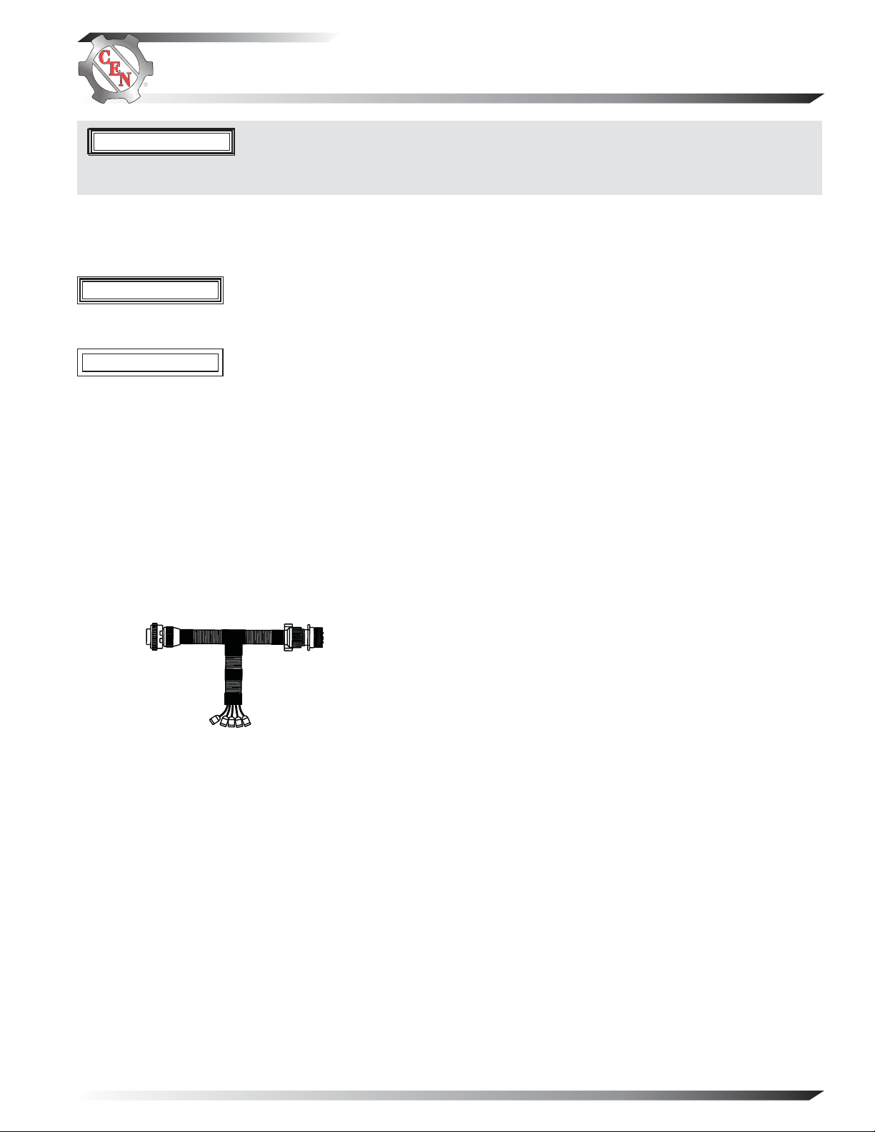
• CEN 5-pin Round Inline Harness Test Tool A10-140
A
E
B
C
D
Figure 1—CEN 5-pin Round Inline Harness Test Tool
A10-140
Testing Guidelines
Professional service technicians rely on the following
guidelines when testing electrical components.
Voltage testing:
• Set meter to proper scale and type (AC or DC).
• Be sure to zero the meter scale or identify the meter
burden by touching meter leads together. Meter burden must be subtracted from final reading obtained.
• Be sure the meter leads touch source area only.
Prevent short circuit damage to test leads or source
by not allowing meter leads to touch other pins or
exposed wires in test area.
• Be sure to use CEN tools designed especially for
troubleshooting CEN alternators when available.
See page 1 for more information.
Resistance (ohm) testing:
• Set meter to proper scale.
• Be sure to zero the meter scale or identify the meter
burden by touching meter leads together. Meter burden must be subtracted from final reading obtained.
• Be sure the meter leads touch source area only.
Prevent altering the reading by not allowing fingers
or body parts to touch meter leads or source during
reading.
• Be sure reading is taken when source is at 70ºF.
Readings taken at higher temperatures will increase
the reading. Conversely, readings taken at lower
temperatures will decrease the reading.
• Be sure to test directly at the source. Testing through
extended harnesses or cable extensions may increase
the reading.
Voltage drop testing:
• Measure voltage between B+ on alternator or source
and B- (ground) on alternator or source. Record
obtained reading. Move to batteries or other source
and measure again between B+ and B- terminals on
battery or other source. Difference between the two
readings represents voltage lost within the circuit
due to but not limited to inadequate cable gage or
faulty connections.
• Voltage drop measurements must be taken with
all electrical loads or source operating.
Dynamic/Live testing:
Definition: Connecting power and ground to a
component to test operation/function out of circuit.
1. Be sure to connect jumper leads directly and securely
to source contacts of the component being tested.
2. Be sure to make any connection to power and ground
at the power supply or battery source terminals. Do
not make connection at component source terminals
as that may create an arc and damage component
source terminals.
TG70C
Page 1
Page 2
Section A: Description and Operation
CEN C505, C527, C531, and C534 Alternators/Regulators Description and Operation
C505, C527, C531, and C534 14 V (360 A) alternators are internally rectified. All windings and current-transmitting
components are non-moving, so there are no brushes or slip rings to wear out.
• When controlled by the A2-334 (C505, C527 or C531 alternator-mounted) or A2-335 (C527 or C531 remote-mounted)
regulator, after engine is running, the alternator is externally energized when the battery master switch on the vehicle
is turned on and regulator receives energize signal through IGN terminal. Regulator monitors alternator rotation and
provides field current only when it detects alternator shaft rotating at or above idle speed. After regulator detects alternator rotation, it gradually applies field current, preventing an abrupt mechanical load on accessory drive system.
The soft start may take up to 20 seconds.
• When controlled by the A2-343 (C527 alternator-mounted), A2-348 (C527, C531, or C534 alternator-mounted) or
A2-350 (C527, C531, or C534 remote-mounted) regulator, the alternator is externally energized when the battery master switch on the vehicle is turned on and provides power to the regulators through the IGN circuit; can also operate
without vehicle connection to the IGN circuit, and instead provide power by sensing rotation through the regulator’s
AC circuit.
After field coil is energized. AC is rectified into DC output through diodes in rectifier housing and supplied to the battery
through the alternator B+ circuit. See schematic diagrams on pages 4 and 5. Alternator output current is self-limiting
and will not exceed rated capacity of alternator. Regulator maintains alternator output voltage at pre-determined regulated setting (see Table 1 or 2 below for setpoints) as vehicle electrical loads are switched on and off.
A2-334 and A2-335 regulators furnished with some units include:
• External IGN terminal for energize connection.
• P terminal that can provide optional AC voltage tap. P terminal signal frequency (Hz) x 10 = alternator shaft rpm.
• Tricolored LED. See page 6.
• Regulator fixed (flat temperature compensation) setpoints shown in Table 1 are selected based on battery type. Battery
type selection and battery maintenance/function are the sole responsibilities of the customer.
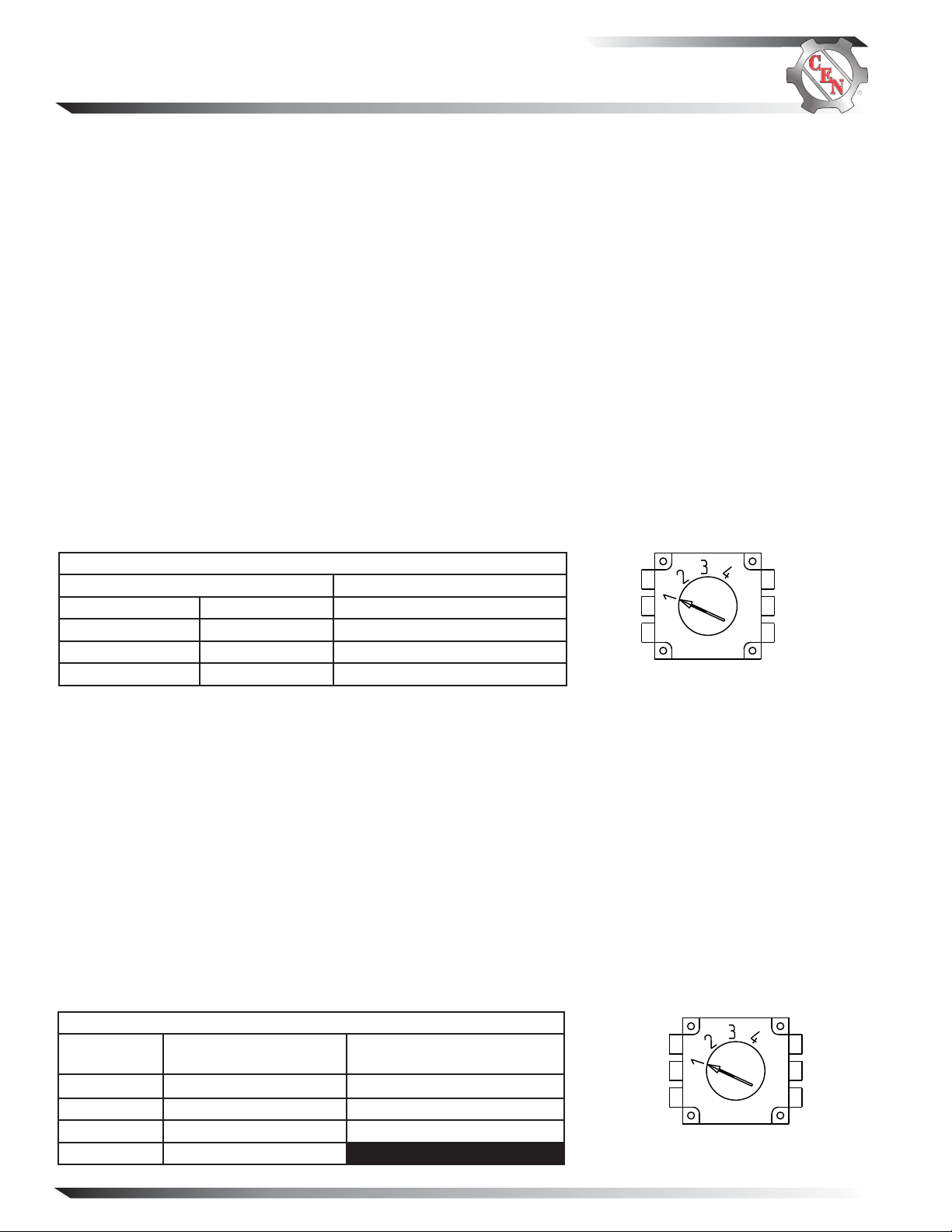
Table 1 — A2-334 & A2-335 Regulator Setpoint Switch Position
Voltage Setpoint (±0.2 V)* Battery Type*
Position 1 14.0 V Maintenance (D Category)
Position 2 14.4 V Maintenance-free (Group 31)
Position 3 14.8 V Maintenance-free (Group 31)
Position 4 15.5 V Battery Isolator in Charging System
* Voltage setpoint can depend on temperature or climate condition, as well as battery type. If boiling or
excessive gassing occurs with higher voltage setpoint, change to next lower voltage setpoint.
Figure 2—Voltage Setpoints
A2-343, A2-348, and A2-350 regulators furnished with some units includes:
• (A2-343 only) No external terminals, only a special 3-pin vehicle harness connector providing one pin for optional AC
voltage tap (PHASE OUT), one pin for DC voltage signal to vehicle electrical system confirming alternator operation
(D+), and one pin for the ignition connection (IGN). This regulator can function with or without vehicle ignition. When
necessary, IGN circuit in vehicle 3-pin harness is connected to vehicle ignition to provide battery voltage when engine
is running. Circuit should be off (no voltage present) when vehicle ignition is off or engine is not running.
• (A2-348 & A2-350 only) P terminal that can provide optional AC voltage tap. P terminal signal frequency (Hz) x 10 =
alternator shaft rpm.
• (All models) Overvoltage cutout (OVCO). See pages 6-7.
• (All models) Tricolored LED. See page 6.
• (All models) Battery type selection and battery maintenance/function are the sole responsibilities of the customer.
• (All models) Temperature-voltage sense/J1939 connector to be used with optional harness.
— When temperature-voltage sense/J1939 harness is not connected, regulator will operate in fixed voltage setting
determined by the select switch position on the bottom of the regulator. See Column 2 in Table 2.
— When temperature-voltage sense/J1939 harness is connected, regulator will automatically optimize the charge volt age for battery type based on temperature. Also, vehicle manufacturer-requested functions of J1939 interface are
available through connector. See Column 3 in Table 2.
Table 2 — A2-343, A2-348, & A2-350 Regulator Voltage/Battery Switch Position
T-VS/J1939 Harness Not
Switch Position
Position 1 13.8 V Maintenance (D Category)
Position 2 14.0 V Maintenance-free (Group 31)
Position 3 14.3 V AGM
Position 4 14.5 V
Connected (Voltage Select)
Page 2
T-VS/J1939 Harness Connected
(Battery Select)
DO NOT USE POSITION # 4
Figure 3—Voltage Setpoints/
Battery Selection
TG70C
Page 3
Section A: Description and Operation (CONT’D)
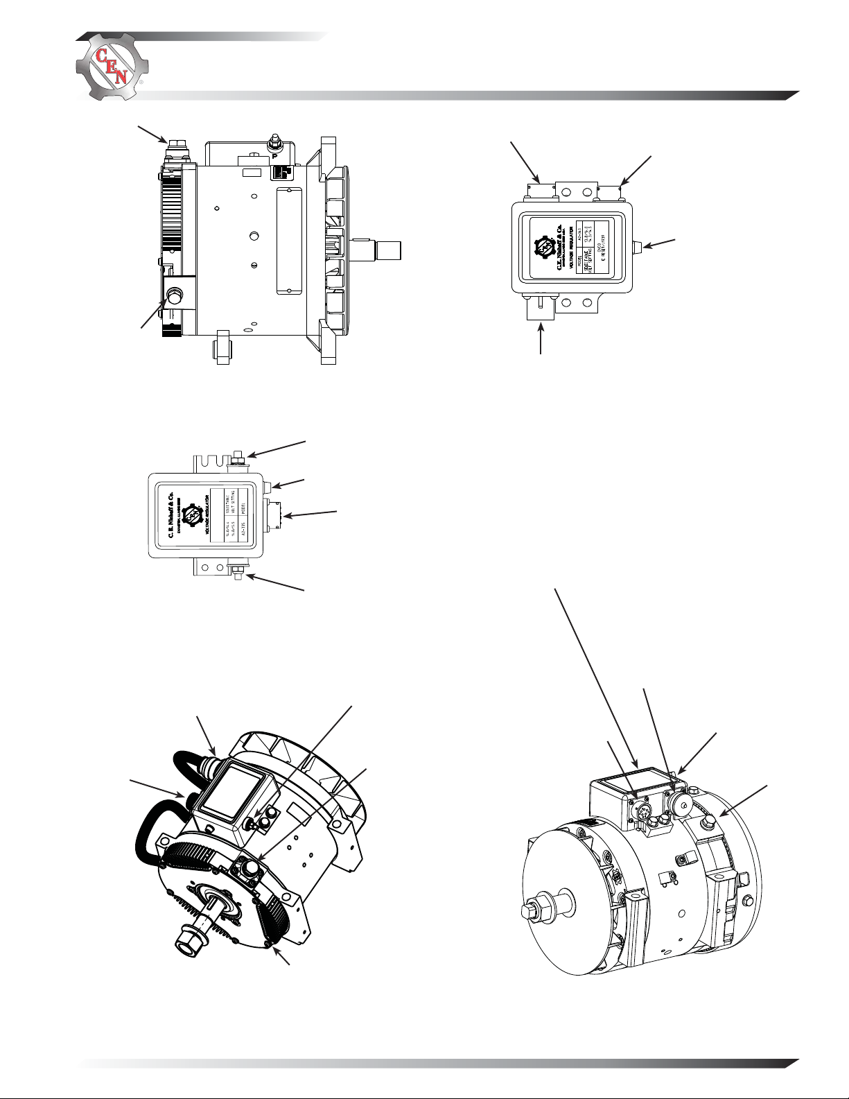
B+ terminal
B– terminal
Figure 4 —C505 Alternator with
A2-334 Regulator Terminals
IGN terminal
LED
Alternatorto-regulator
connector
Alternator-toregulator connector
Vehicle connector
Battery-voltage
sense/J1939
connector
LED
Figure 7 — A2-343
Regulator Connections
Regulator Terminals (A2-335 shown)
Alternatorto-regulator
connector
Battery-voltage
sense/J1939
connector
Figure 6 — C527/C531 Alternator with
A2-348/A2-350 Regulator Terminals
P terminal
Figure 5 — A2-334/A2-335
Regulator P terminal
B– terminal
(A2-348 shown)
B+ terminal
Regulator P terminal
Battery-voltage
sense/J1939
connector
Alternatorto-regulator
connector
Figure 8 — C534 Alternator with
A2-348/A2-350 Regulator Terminals
(A2-348 shown)
B+ terminal
B– terminal
TG70C
Page 3
Page 4

Section B: Schematic Diagram
R
BK
BR
G
W
Figure 9 — C505, C527, and C531 w/A2-334/A2-335 Regulator Schematic Diagram
R
BK
BR
G
W
Page 4
Figure 10 — C527 w/A2-343 Regulator Schematic Diagram
TG70C
Page 5

BR
Section B: Schematic Diagram (CONT’D)
BK
R
W
G
Figure 11 — C527, C531, and C534 w/A2-348/A2-350 Regulator Schematic Diagram
TG70C
Page 5
Page 6

Section C: On-Vehicle Troubleshooting
A2-334 and A2-335 Regulator Troubleshooting
A2-334 regulator is mounted directly to the outside of the alternator. A2-335 regulator is mounted remotely on the
vehicle and connected to alternator with extended wiring harnesses.
Main diagnostic feature of regulators consists of a tricolored (green, amber, red) LED located on the end of the regulator.
The LED works like a voltmeter, measuring charging voltage. See Table 3 for diagnostic features and LED explanations.
TABLE 3 – A2-334 & A2-335 Regulator LED Diagnostics with Engine On*
LED COLOR
GREEN Solid
AMBER Flashing *
Solid
RED Flashing
* LED will flash AMBER for one minute upon start-up/shutdown—if regulator does not sense alternator rotation, regulator will time out.
Alternator and regulator operating normally.
Alternator fault — No output.*
Low system voltage — Electrical load exceeds
alternator rating at present rotor speed.
System voltage higher than setpoint.
No power to ignition or regulator is defective.OFF
STATUS
No action required.
Replace alternator.*
When loads decrease or speed increases, LED
should be solid GREEN. If not, check drive belt
and charging system connections.
May occur during normal load switching.
Go to Chart on page 8.
ACTION
A2-343, A2-348, and A2-350 Regulator Troubleshooting
A2-343 and A2-348 regulators are mounted directly to the outside of the alternator. A2-350 regulator is mounted
remotely on the vehicle and connected to alternator with extended wiring harnesses.
Main diagnostic feature of regulators consists of a tricolored (green, amber, red) LED located on the end of the regulator.
The LED works like a voltmeter, measuring charging voltage. See Table 4 for diagnostic features and LED explanations.
These regulators have OVCO (overvoltage cutout) that will trip at vehicle electrical system voltage above 16 volts that
exists longer than 3 seconds. OVCO feature detects high voltage and reacts by signaling relay in alternator field circuit
to open. This turns off alternator (LED is f lashing RED). OVCO circuit is reset when engine is restarted or when system
voltage drops to 11.5 V. Regulator then regains control of alternator output voltage.
An additional temperature-voltage sense/J1939 harness may or may not be used with the A2-343, A2-348, and A2-350
regulators:
• When optional temperature-voltage sense/J1939 harness is not connected, regulator will operate in fixed voltage
setting determined by the select switch position on the bottom of the regulator (see page 2).
• When optional temperature-voltage sense/J1939 harness is connected, regulator will automatically optimize the
charge voltage for battery type selected based on temperature. See page 2. Also, vehicle manufacturer-requested
functions of J1939 interface are available through connector.
TABLE 4 — A2-343, A2-348, & A2-350 Regulator LED Diagnostics with Engine On*
LED COLOR STATUS
GREEN Solid
AMBER Solid
Flashing*
RED Solid
Flashing
* LED will flash AMBER for one minute upon start-up/shutdown—if regulator does not sense alternator rotation, regulator will time out.
Alternator and regulator operating normally.
Low system voltage — Electrical load exceeds
alternator rating at present rotor speed.
Alternator fault — No output.*
High system voltage – May occur during
normal load switching.
OVCO tripped.
No power to ignition or regulator is defective.OFF
No action required.
When loads decrease or speed increases, LED
should be solid GREEN. If not, check drive belt and
charging system connections.
Replace alternator.*
Indicates voltage above setpoint but below OVCO
threshold (less than 16 volts).
Indicates voltage exceeds 16 V for more than
3 seconds. System diagnosis required. See “OVCO
Troubleshooting” section on page 7.
Go to Chart on page 8.
Page 6
ACTION
TG70C
Page 7

Section C: On-Vehicle Troubleshooting (CONT’D)
Temperature-Voltage Sense/J1939 Harness Troubleshooting
To verify temperature sense function on T-VS/J1939 harness:
1. With master battery switch on, key on, engine on, and loads off, apply a warm air source (such as a hair dryer, not to
heat above 120°F) to battery negative terminal of harness. Charge voltage should decrease as temperature increases.
If charge voltage increases or shows no change as temperature increases, go to step 2.
2. If charge voltage increases or shows no change as temperature increases from step 1:
a. With master battery switch on, key off, and engine off, check for battery voltage across pin E in 5-pin connector
(pin J in 10-pin connector) on T-VS/J1939 ha rness and ground w ith meter in VDC sc ale. If no battery volta ge exists,
entire harness is defective and must be replaced. If battery voltage exists, go to step 2b.
b. With master battery switch on, key off, and engine off, check for a resistance reading of 5-15K Ohms at 70ºF (20ºC)
across pin B in 5-pin connector (pin H in 10-pin connector) on T-VS/J1939 harness and ground with meter in K
Ohm scale. (Note: If ambient temperature is higher, resistance will measure less than listed and vice versa.) If test
fails, see CEN Service Bulletin SB27. If test passes, go to chart on page 8.
OVCO Troubleshooting
Shut down vehicle and restart engine. If alternator functions normally after restart, a “no output condition” was normal
response of voltage regulator to “high voltage” condition. Inspect condition of electrical system, including loose battery
cables, both positive and negative. If battery disconnects from system, it could cause “high voltage” condition in electrical
system, causing OVCO circuit to trip.
If you have reset alternator once, and electrical system returns to normal charge voltage condition, there may have been
a one time, high voltage spike, causing OVCO circuit to trip.
If OVCO circuit repeats cutout a second time in short succession and shuts off alternator field circuit, try third restart.
If OVCO circuit repeats cutout, check that pin A in alternator-to-regulator harness is not shorted to B–. If it is shorted,
alternator is defective. If not, regulator is defective.
TG70C
Page 7
Page 8
Section C: On-Vehicle Troubleshooting (CONT’D)
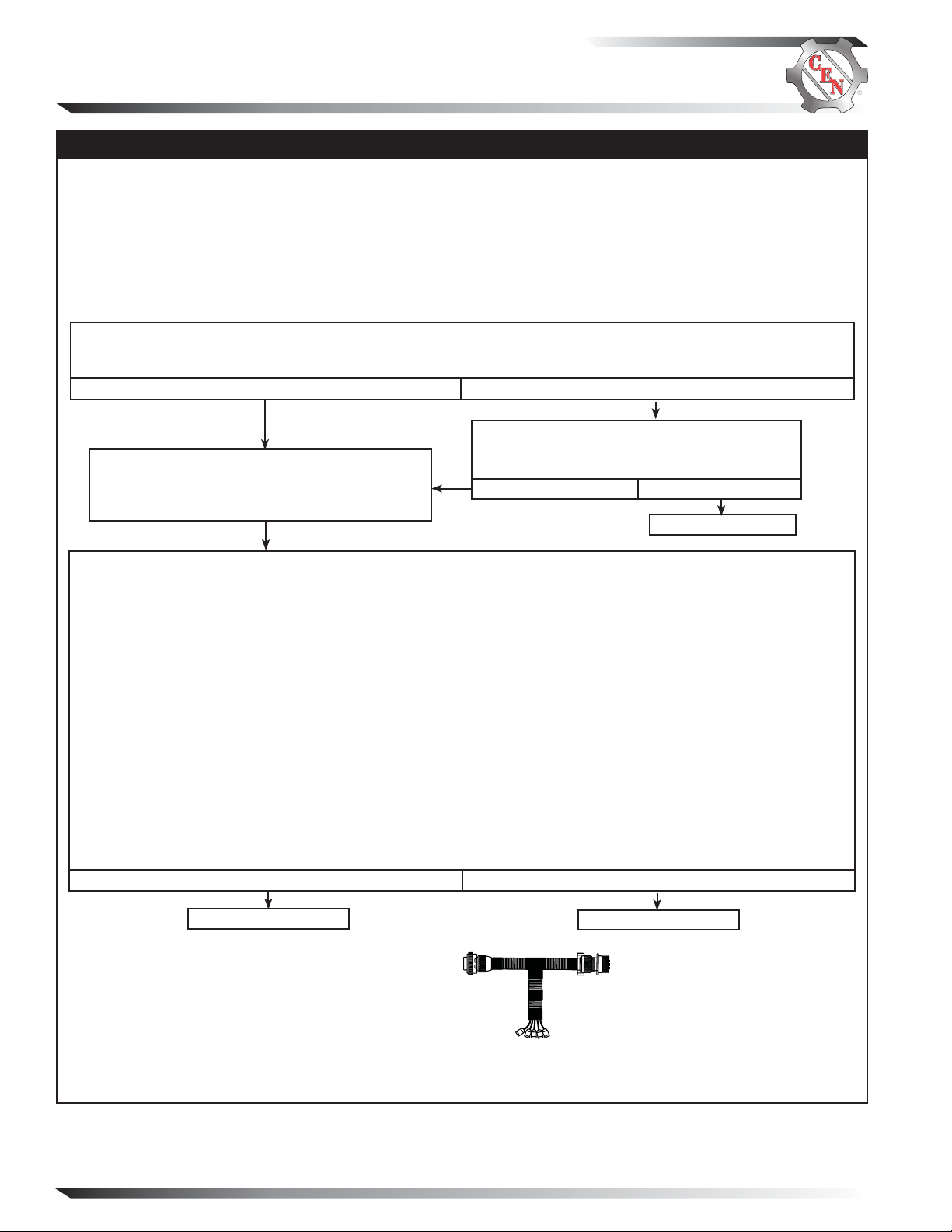
No Alternator Output – Test Charging Circuit
• TEST MEASUREMENTS ARE TAKEN ON HARNESS PLUG AT ALTERNATOR. TEST MEASUREMENT AT AN
EXTENDED HARNESS PLUG MAY AFFECT RESULTS.
• REMOTE-MOUNTED REGULATORS: CHECK CONDITION OF FUSES IN WIRING HARNESS BEFORE TROUBLE-
SHOOTING.
• BEFORE STARTING DIAGNOSTIC SEQUENCE, VERIFY THE FOLLOWING AND REPAIR/REPLACE IF NOT
TO SPEC:
—BATTERIES FOR STATE-OF-CHARGE (12.3-12.6 V), CONDITION, AND SECURE CONNECTIONS
—MASTER BATTERY SWITCH FOR FUNCTION
MASTER BATTERY SWITCH ON, KEY ON, ENGINE ON: Test for battery voltage at B+ terminal on alternator
to ground, then at IGN terminal on regulator to ground (See page 2 for more information).
Does battery voltage exist at both locations?
Yes
ENGINE OFF: Disconnect 5-pin alternator-toregulator harness plug at regulator and connect
CEN A10-140 inline test tool to harness plug end
only. Make sure connections are secure.
Repair vehicle wiring as necessary. Run engine
and re-test charging circuit. Is charging system
performing properly?
No
No
Yes
System is operative.
MASTER BATTERY SWITCH ON, KEY OFF, ENGINE OFF: Readings of all five tests must pass.
1. Battery voltage test: Connect DMM red lead to socket D in test tool. Connect DMM black lead to socket C in test
tool. Battery voltage should exist.
2. Field coil resistance test: Set DMM to ohms test. Field resistance between socket A in test tool and B+ terminal
on alternator should measure nominal 1.0-1.5 ± 0.2 ohms. Field coil is defective if reading is less than 0.5 ohms or
greater than 3 ohms.
3. Significant magnetism test:
a. Insert one end of jumper wire in socket A in test tool. Momentarily (1 sec.) touch other end of jumper wire
to alternator B – terminal. Spark will occur at B– terminal. Touch steel tool to shaft to detect significant
magnetism.
b. Remove jumper wire.
4. Phase supply test: Set DMM to diode test. Connect DMM black lead to socket B in test tool. Connect red lead to
alternator B+ terminal. DMM should read blocking in this direction. Then reverse leads. DMM should read flow
in this direction. Repeat for socket B and B– terminal. Tests should read flow in one direction and blocking in
the other direction.
5. Alternator temperature sensor circuit test: Set DMM to ohms test. Sensor resistance between socket E in test tool
and B– terminal on alternator should measure 80-130K ohms at 70ºF (20ºC). Note: If ambient temperature is
higher, resistance will measure less than listed and vice versa.
Yes
Regulator is defective.
Alternator is defective.
No
SOCKET CONNECTIONS
Socket A F–
Socket B Phase
Socket C B –
Socket D B+
Socket E Temp sense
A
E
B
C
D
Figure 12 – CEN 5-pin A10-140 Inline Harness Tool
Socket Connections
If you have questions about your a lternator or any of these instructions, or if you need to locate a Factory Authorized Serv ice Dealer, please contact us at:
C. E. Niehoff & Co.• 2021 Lee Street • Evanston, IL 60202 USA
Page 8
TEL: 800.643.4633 USA and Canada • TEL: 847.866.6030 outside USA and Canada • FAX: 847.492.1242
E-mail us at service@CENiehoff.com
TG70C
 Loading...