

Page 1
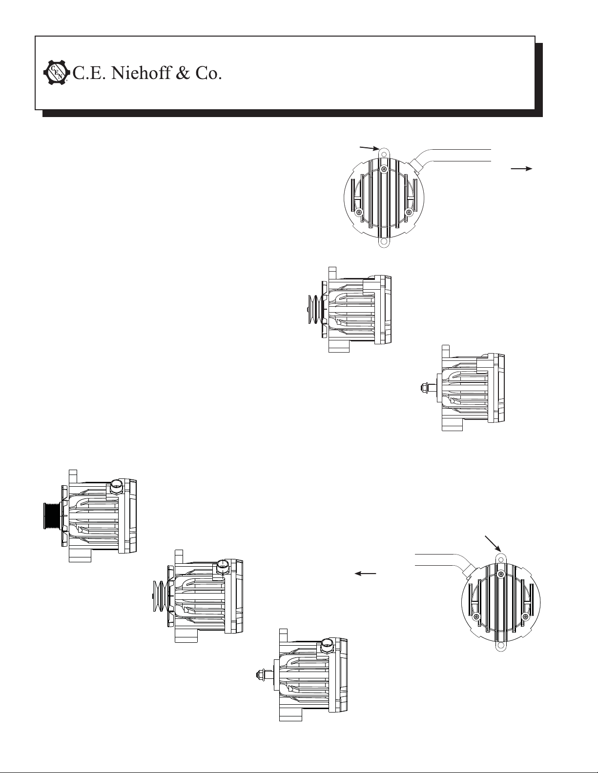
1. Install alternator with cover oriented in a position
that allows best vertical air flow through fins on
anti-drive end. See Figure 1 and 2:
a. C180-1, C180-2, and C181-1 units are shipped
with pulley/fan, f lat washer, and nut installed.
b. C180 and C181 units are shipped with shaft
collar, flat washer, and nut. Remove and
discard shaft collar. Install pulley/fan and
furnished flat washer. Torque furnished nut to
68 Nm/50 lb. ft.
c. Use Grade 5 flange bolt and locking type flange
nuts to mount alternator. Self-locking type
screw is required to clamp up belt adjusting
bracket. Tighten the adjusting bracket before
tightening alternator mounting bolts. Torque
12mm x 1.75 mounting bolts to 50 Nm/ 37 lb. ft.
d. Follow vehicle manufacturer’s recommenda-
tions for belt tension.
2. Connect alternator and rectifier/regulator:
• C180-1—see page 2
• C180-2—see page 3
• C181-1—see page 4
• C180 and C181 alternators are replacements for
their corresponding dashed numbered alterna tors. Follow appropriate instructions listed above.
C180-1 Alternator w/ A8-206 Rectifi er-Regulator
C180-2 Alternator w/ A8-207 Rectifi er-Regulator
C181-1 Alternator w/ A8-208 Rectifi er-Regulator
C180/C181 Alternators
Installation Instructions
Mounting lugs (2)
To rectifier-regulator
C181-1
C181
C180-2
Figure 1 - C181-1/C181 Alternator Details
Mounting lugs (2)
To rectifier-regulator
C180-1
C180
Page 1 of 4
Figure 2 - C180-2/C180-1/C180 Alternator Details
II162A
Page 2
C180-1 Alternator
w/ A8-206 Rectifi er-Regulator
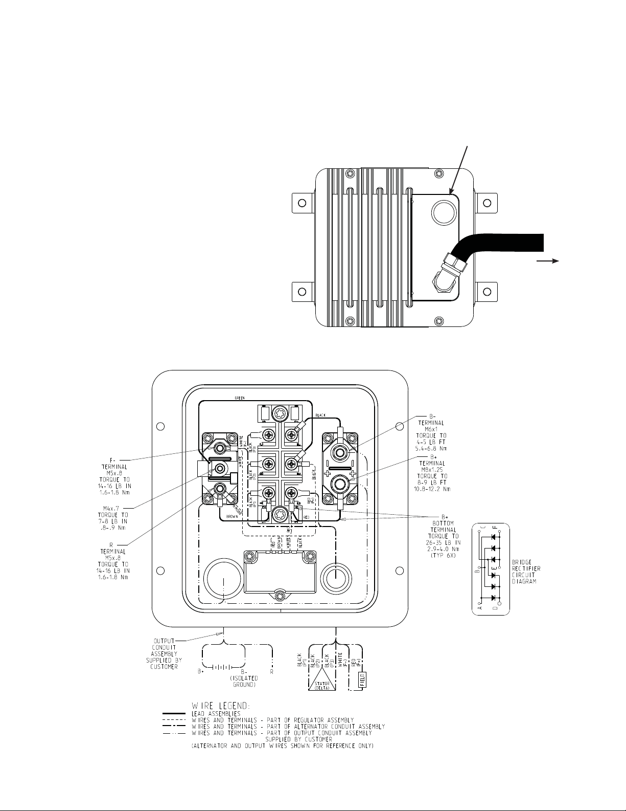
1. Install rectifier-regulator assembly in location
determined by customer, using hardware and
torque specified by customer.
2. Remove shipping spacers from both sides of
rectifier-regulator.
3. Connect rectifier-regulator to alternator
with wiring conduit shown in
Figure 3 and 4.
4. Output conduit supplied by customer
connects rectifier-regulator with
customer circuit and consists of
B+ and B– output leads plus
R terminal lead if used.
5. R circuit current: 3 A max
Square wave signal: 0-30 V
Alternator speed formula: RPM=f(Hz)•10
6. Alternator is configured for selfenergization. Regulator brown wire
is connected to R circuit. If external
energize is required, remove brown
wire between R terminal and module
terminal A. Connect energize signal,
which must open when alternator shaft
is not rotating.
7. Series connected isolation diode in the B+ circuit is
not permissible.
8. When wiring inside rectifier-regulator cover is
complete, re-install cover and torque hardware
to 5.4 Nm/48 lb. in.
See step 2.
M25 x 1.25 pipe thread
for connecting output
conduit assembly
To alternator
Figure 3 - A8-206 Rectifier-Regulator Cover Connections
Page 2 of 4
Figure 4 - C180-1/A8-206 Component Interconnect Diagram
II162A
Page 3

C180-2 Alternator
w/ A8-207 Rectifi er-Regulator
1. Install rectifier-regulator assembly in location
determined by customer, using hardware and
torque specified by customer.
2. Remove shipping spacers from both sides of
rectifier-regulator.
3. Connect rectifier-regulator to alternator
with wiring conduit shown in
Figure 5 and 6.
4. Output conduit supplied by customer
connects rectifier-regulator with
customer circuit and consists of
B+ and B– output leads plus
R and D+ terminal leads if used.
5. R circuit current: 3 A max
Square wave signal: 0-30 V
Alternator speed formula: RPM=f(Hz)•10
6. Alternator is configured for selfenergization.
7. D+ terminal is the charge warning
lamp (CWL) connection.
8. Series connected isolation diode in the
B+ circuit is not permissible.
9. When wiring inside rectifier-regulator cover is
complete, re-install cover and torque hardware
to 5.4 Nm/48 lb. in.
See step 2. M25 x 1.25 pipe thread for
connecting output conduit assembly
To alternator
Figure 5 - A8-207 Rectifier-Regulator Cover Connections
Page 3 of 4
Figure 6 - C180-2/A2-207 Component Interconnection Diagram
II162A
Page 4

C181-1 Alternator
w/ A8-208 Rectifi er-Regulator
1. Install rectifier-regulator assembly in location
determined by customer, using hardware and
torque specified by customer.
2. Remove shipping spacers from both sides of
rectifier-regulator.
3. Connect rectifier-regulator to alternator
with wiring conduit shown in
Figure 7 and 8.
4. Output conduit supplied by customer
connects rectifier-regulator with
customer circuit and consists of
B+ and B– output leads plus
R and D+ terminal leads if used.
5. R circuit current: 3 A max
Square wave signal: 0-30 V
Alternator speed formula: RPM=f(Hz)•10
6. Alternator is configured for selfenergization.
7. D+ terminal is the charge warning
lamp (CWL) connection.
8. Series connected isolation diode in the
B+ circuit is not permissible.
9. When wiring inside rectifier-regulator cover is
complete, re-install cover and torque hardware
to 5.4 Nm/48 lb. in.
See step 2. M25 x 1.25 pipe thread for
connecting output conduit assembly
To alternator
Figure 7 - A8-208 Rectifier-Regulator Cover Connections
Figure 8 - C181-1/A2-208 Component Interconnection Diagram
C. E. Niehoff & Co. • 2021 Lee Street • Evanston, IL 60202 Tech Services Hotline 800-643-4633
Page 4 of 4
II162A
 Loading...