

Page 1
C.E. Niehoff & Co.
See Pages 2, 3, and 4 for Technical Specifi cations
This symbol is used to indicate presence
WARNING
of hazards that can cause severe
personal injury, death or substantial
property damage.
This symbol is used to indicate presence
CAUTION
of hazards that can cause minor
personal injury or property damage.
This alternator contains no serviceable
WARNING
parts except pulley, fan, and regulator.
Manufacturer’s hazardous location
certification is void if repaired except for
the pulley, fan, and regulator which may
be replaced with factory parts.
Explosion hazard—substitution of compo-
WARNING
nents may impair suitability for Class I,
Division 2.
Risque d’explosion—la substitution de
ADVERTISSEMENT
composants peut rendre ce matériel
inacceptable pour les emplacements
de Classe I, Division 2.
Explosion hazard—do not replace any
WARNING
component unless power has been
switched off or the area is known to be
non-hazardous.
Risque d’explosion—couper le courant
ADVERTISSEMENT
ou s’assurer que l’emplacement est
désigné non dangereux avant de
replacer le composants.
Explosion hazard—do not disconnect
WARNING
equipment unless power has been
switched off or area is known to be
non-hazardous.
Risque d’explosion—avant de décon-
ADVERTISSEMENT
necter l’equipement, couper le courant
ou s’assurer que l’emplacement est
désigné non dangereux.
Installation Instructions
Improper installation of alternator in an
WARNING
explosive environment can cause severe
personal injury, death, or substantial
property damage. Alternator must be
installed by a qualified person trained in
the installation of alternators in explosive
atmospheres. For CSA and UL classifica tions and atmospheric conditions, see
page 2 of these instructions.
1. Mount alternator on a suitable bracket and
secure with hardware per alternator drawing
on page 2 of these instructions.
© 2014, C. E. Niehoff & Co. All rights reserved.
SM40A
C130, C131, and C132 Alternators
Combo Guide
2. Remove anti-drive end (ADE) cover from the
alternator.
3. One of the following two alternator circuits
described below is required to operate alternator.
a. If alternator is to be self-energized, be sure
the link is connected between B+ stud and
IGN terminal (as shipped). This alternator
relies on residual magnetism to operate.
Observe all applicable safety procedures when
performing the following operation: If neces sary, restore lost magnetism by connecting
test light between B+ stud and R terminal for
1-3 seconds while alternator shaft IS NOT
TUR NING and battery is connected to illumi nate test light. Check for magnetic field at
pulley. If magnetized, remove test light, start
alternator, and test.
b. If the alternator is to be energized through
ignition key, connect energizing signal lead
directly to IGN terminal and remove link
between B+ stud and IGN terminal. Torque
IGN terminal bolt to 2 Nm/18 lb. in. This
alternator relies on residual magnetism to
operate. Ensure battery voltage is present at
IGN terminal. Observe all applicable safety
procedures when performing the following
operation: If necessary, restore lost magnetism
by connecting test light between B+ stud and
R terminal for 1-3 seconds while alternator
shaft IS NOT TURNING and battery is con nected to illuminate test light. Check for
magnetic field at pulley. If magnetized, remove
test light, start alternator, and test.
4. Connect B+ cable to B+ stud on alternator. See
wire chart on page 3 for correct cable size and
length. Torque terminal nut to 9 Nm/80 lb. in.
5. Connect R lead to R terminal on alternator if required for vehicle operation (optional connection).
Torque R terminal bolt to 2 Nm/18 lb. in.
6. Connect B– cable to B– terminal stud on alternator (B– is an isolated ground). B– cable gauge
should be same as gauge of battery positive
cable. Torque terminal nut to 9 Nm/80 lb. in.
Supply wires suitable for rated
Utiliser des câbles d’alimentation
7. Perform a final inspection on the installation.
8. Re-install anti-drive end cover on alternator. Posi-
9. Install suitable alternator drive belt.
10. Start engine. Confirm operation of charging
CAUTION
load at 90°C ambient shall not
exceed 200°C.
ATTENTION
appropriée pour 200ºC.
tion louvers consistent with deflection of rain or
fluids during normal operating conditions. Fasten
with screws and washers in four places. Use a
suitable adhesive such as Loctite® 222. Follow
manufacturer’s instructions. Torque screws to 3.4
Nm/30 lb. in.
system meets specification.
Page 1
Page 2
Installation Instructions (CONT’D)
Page 2
SM40A
Page 3

Installation Instructions (CONT’D)
(OPTIONAL)
on page 1
on page 1
Step 6 on page 1
SM40A
Page 3
Page 4
Installation Instructions (CONT’D)
0
10
20
30
40
50
60
70
0 1000 2000 3000 4000 5000 6000 7000 8000
RPM
OUTPUT/ A
0
1
2
3
4
5
6
7
TORQUE/Nm
OUTPUT/ A TORQ UE/ Nm
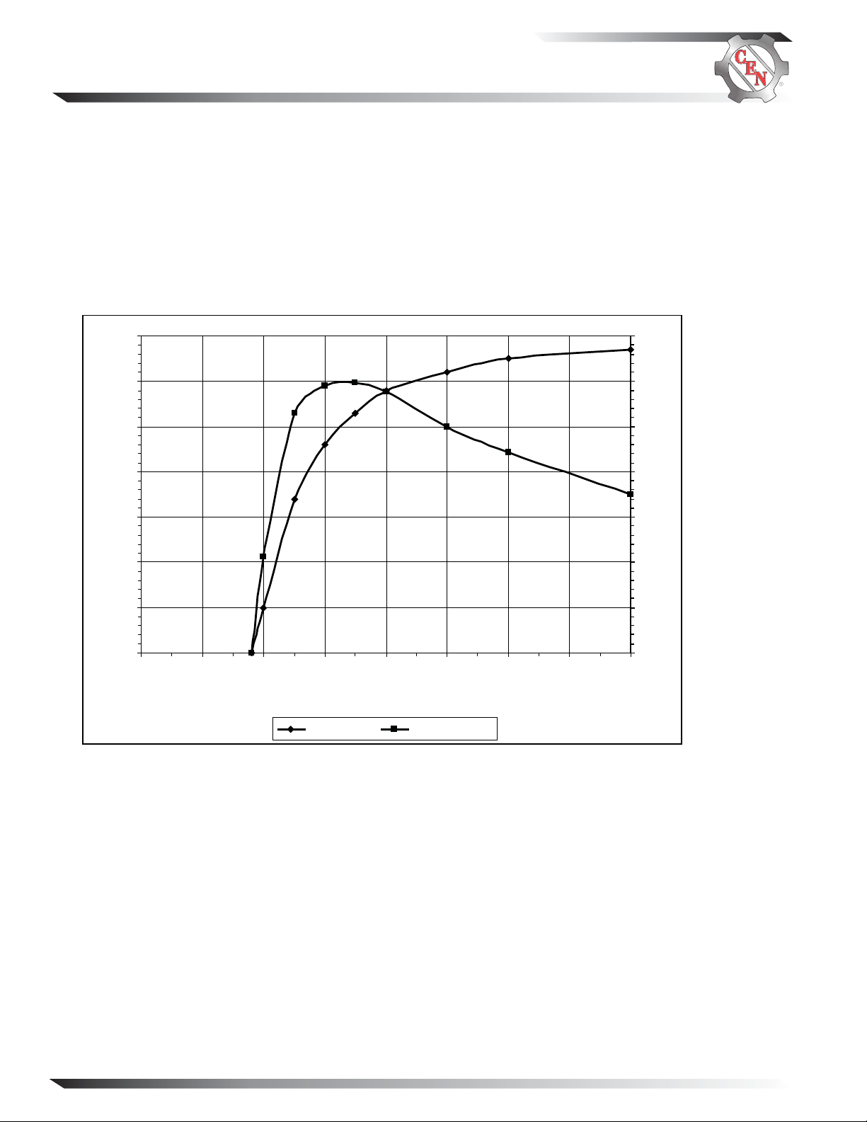
ALTERNATOR CHARACTERISTICS FOR 28 VOLTS/ 60 AMPS:
APPLICABLE MODELS: C130, C132
OUTPUT CURVE: OUTPUT AMPERES VERSUS ALTER NATOR SHAFT SPEED IN RPM AT 28.0 VOLTS.
TORQUE CURVE: DRIVE TORQUE IN Nm VERSUS ALTERNATOR SHAFT SPEED IN RPM REQUIRED TO
PRODUCE OUTPUT CURVE.
ALL MEASUREMENTS DEPICTED ON PERFORMANCE CURVES ARE TAKEN AT 22ºC/72ºF AMBIENT
TEMPERATURE (UNLESS OTHERWISE SPECIFIED) AND A STABILIZED MACHINE TEMPERATURE
AT MA XIMUM OUTPUT WITH VOLTAGE CONSTANT AS SPECIFIED.
ABBREVIATIONS:
RPM REVOLUTIONS PER MINUTE
Nm NEWTON-METER
Conversion: 1 Nm = 8.85 Pound Inch (LBIN)
Page 4
SM40A
Page 5

Installation Instructions (CONT’D)
ALTERNATOR CHARACTERISTICS FOR 14 VOLTS/ 70 AMP:
APPLICABLE MODELS: C131
OUTPUT CURVE: OUTPUT AMPERES VERSUS ALTERNATOR SHAFT SPEED IN RPM AT 13.8
VOLTS.
TORQUE CURVE: DRIVE TORQUE IN Nm VERSUS ALTERNATOR SHAFT SPEED IN RPM
REQUIRED TO PRODUCE OUTPUT CURVE.
SM40A
ALL MEASURMENTS DEPICTED ON PERFORMANCE CURVES ARE TAKEN AT 104°F (40°C)
AMBIENT TEMPERATURE (UNLESS OTHERWISE SPECIFIED) AND A STABILIZED MACHINE
TEMPERATURE AT MAXIMUM OUTPUT WITH VOLTAGE CONSTANT AS SPECIFIED.
ABBREVATIONS:
RPM REVOLUTIONS PER MINUTE
Nm NEWTON-METER
Conversion: 1 Nm = 8.85 Pound Inch (LBIN)
Page 5
Page 6

Parts Replacement Instructions
Pulley Replacement
Remove existing pulley (see Figure 1):
1. Remove pulley nut and washer.
2. Remove and discard pulley.
Install new pulley (see Figure 1):
1. Install new pulley and fasten with pulley nut and
washer.
2. Keep pulley, fan, and shaft from spinning while
torquing pulley nut to 68 Nm/50 lb. ft.
Drive End (DE) Fan Replacement
Remove existing DE fan (see Figure 1):
1. Remove pulley nut and washer.
2. Remove pulley.
3. Remove woodruff key and discard fan.
Install new DE fan (see Figure 1):
1. Place new fan on shaft.
2. Install woodruff key.
3. Install pulley and fasten with pulley nut and washer.
4. Keep pulley, fan, and shaft from spinning while
torquing pulley nut to 68 Nm/50 lb. ft.
Anti-drive End (ADE) Cover Replacement
Remove ADE Cover on Alternator (see Figure 1):
1. Remove hardware and discard ADE cover plate.
Install New ADE Cover on Alternator (see Figure
1):
1. Install new ADE cover plate. Position louvers consistent with def lection of rain or fluids during normal
operating conditions.
2. Fasten in four places with screws and washers. Use a
suitable adhesive such as Loctite® 222. Follow manufacturer’s instructions. Torque screws to 3.4 Nm/30
lb. in.
Fan
Woodruff
Key
Alternator
Pulley
Regulator
F
E
ADE Cover
Page 6
Figure 1 – Parts Replacement
SM40A
Page 7

Parts Replacement Instructions (CONT’D)
Anti-drive End (ADE) Regulator
Replacement
Remove ADE Regulator on Alternator (see Figures 1
and 2):
1. Remove hardware and ADE cover plate.
2. Remove and discard hardware attaching regulator
to plate.
3. Unplug alternator-to-regulator harness from
regulator.
4. Discard regulator.
Regulator
Install New ADE Cover on Alternator (see Figures 1
and 2):
1. Plug alternator-to-regulator harness securely into new
regulator.
2. Install new regulator on plate using new screws from
kit. Use a suitable adhesive such as Loctite® 222.
Follow manufacturer’s instructions. Torque screws to
2.8 Nm/25 lb. in.
3. Re-install ADE cover plate. Position louvers consis-
tent with def lection of rain or fluids during normal
operating conditions.
4. Fasten in four places with screws and washers. Use a
suitable adhesive such as Loctite® 222. Follow manufacturer’s instructions. Torque screws to 3.4 Nm/
30 lb. in.
Alternator-to-regulator harness plug
SM40A
E
D
C
B
A
Figure 2 –Regulator Replacement
Page 7
Page 8

Troubleshooting
Tools and Equipment for Bench Testing
• Testing Electrical Components, page 12.
• Digital Multimeter (DMM)
• Ammeter (digital, inductive)
• Test bench with 5–10 hp motor able to drive
alternator to 8000 rpm. Mount alternator per test
bench manufacturer’s instructions. Make sure test
bench batteries are charged at 95% or higher.
Bench Tests
• Voltage at regulator setpoint ±0.2 V is considered
“normal.”
• Alternator rated output (listed on nameplate) ±10%
is determined at 5000 rpm at 72ºF.
• Run alternator for 15 minutes to stabilize readings.
• Alternator/regulator should be connected to test
bench per schematic diagram on page 3.
test bench, make sure batteries
CAUTION
are connected per schematic
diagram on page 3.
Alternator/regulator will not
BENCH TEST 1: NO-LOAD TEST
With battery connected and nominal electrical load
set as shown in Table 1, run alternator at 2000-2500
rpm shaft speed.
• If alternator passes No-Load Test, go to Full Load
• If alternator fails No-Load Test, go to Static Tests.
BENCH TEST 2: FULL LOAD TEST
With battery connected and electrical load set as
shown in Table 2, run alternator at 5000-8000 rpm
shaft speed.
• If alternator passes Full Load Test, alternator is
• If alternator fails Full Load Test, go to Static Tests.
NOTICE
function without being properly
connected to power source.
Test.
TAB LE 1 No-Load Test
ALT. AMPS VOLTS
C130
C132
C131 5 - 40 14±0.2
functioning properly.
TABLE 2 Full Load Test
ALT. AMPS VOLTS
C130
C132
C131 70 14±0.2
When connecting alternator to
28V
5-40 28±0.2
28V
60 28±0.2
Alternators should not be powered
WARNING
during static tests. Connections
required during testing can cause
shorts and damage alternator.
Static tests should confi rm
NOTICE
on-vehicle and on-bench tests.
Tools and Equipment for Static Testing
• Testing Electrical Components, page 12.
• Digital Multimeter (DMM)
• Ammeter (digital, inductive)
• Regulator tester
Regulator Test
• Regulator tester tests all regulator functions.
• If regulator tester is used, follow regulator tester
manufacturer’s instructions.
• If regulator tester is not available, regulator can
only be tested for a shorted field-switching transistor. Follow Regulator Test below.
REGULATOR TEST: CHECK FOR SHORTED FIELDSWITCHING TRANSISTOR
1. Set DMM to diode test scale.
2. See Figure 3. Connect one meter lead to pin C in
regulator receptacle and connect other lead to
pin A in regulator receptacle. Observe meter reading. Reverse leads and observe meter reading. If
DMM reads zero in either direction, field-switching
transistor is shorted. Replace regulator. If regulator
failure is indicated, field coil failure must also be
suspected.
CONNECTIONS
A B–
B IGN
C F–
D Phase (R)
E B+
Figure 3 Regulator Harness Connections
Regulator Receptacle
Alternator-to-Regulator
Harness Plug
Page 8
SM40A
Page 9

Troubleshooting (CONT’D)
Internal Circuit Tests
• Internal Circuit Tests will show the condition of
internal circuits through the alternator via alternatorto-regulator harness.
• Some disassembly will be necessary to access the
components. Do not disassemble the alternator
beyond what the tests require.
• Before performing Internal Circuit Tests, check for
visible signs of damaged components.
• The expected reading/result listed for each test must
be obtained. Replace any component that fails the test.
TABLE 3 Pin-to-Pin Tests (See Figure 4)
TEST
NO.
1
2*
3
4
5
6
7
8
9
10
11
12
13
* Applies only when f ield coil is att ached to rectifier/housing assembly.
METER SCALE
& SYMBOL
Ohms Ω
Ohms Ω
Ohms Ω
Ohms Ω
Ohms Ω
Ohms Ω
Diode Test
Diode Test
Diode Test
Diode Test
Ohms Ω
Ohms Ω
Diode Test
Diode Test
Ohms Ω
METER (+) LEAD
CONNECTION
Socket A
Socket E
Socket E
Socket E
Socket C
Socket C
Socket D
Alt. B+ Terminal
Socket D
Alt. B– Terminal
Socket E
Socket A
Alt. B+ Terminal
Alt. B– Terminal
R Terminal
Failure to perform the complete
series of Internal Circuit Tests can
result in improper diagnosis of
alternator condition.
METER (–) LEAD
CONNECTION
Alternator Case
Socket C
Alt. B– Terminal
Alternator Case
Alt. B– Terminal
Alternator Case
Alt. B+ Terminal
Socket D
Alt. B– Terminal
Socket D
Alt. B+ Terminal
Alt. B– Terminal
Alt. B– Terminal
Alt. B+ Terminal
Alternator Case
NOTICE
CAUTION
TESTED CIRCUIT
Isolated ground
Field coil resistance
Field coil insulation
Field coil insulation
Field coil insulation
Field coil insulation
Phase winding and diode
Phase winding and diode
Phase winding and diode
Phase winding and diode
Regulator power circuit
Regulator ground circuit
All diodes in parallel
All diodes in parallel
Stator insulation
Service technicians should
understand and follow all
information in the service manual
when servicing the product.
EXPECTED
READING
OL (infinity)
4.8±0.2 ohms
OL (infinity)
OL (infinity)
OL (infinity)
OL (infinity)
<0.7 volts (flow)
OL (blocking)
OL (blocking)
<0.7 volts (flow)
0 ohms
0 ohms
OL (blocking)
<0.8 volts (flow)
OL (infinity)
CONNECTIONS
A B–
B IGN
C F–
D Phase (R)
E B+
Alternator-to-Regulator Harness Connector
SM40A
Figure 4 Alternator Connections
B+
IGN
R
DE
C
AB
B−
Page 9
Page 10

Exploded Parts View
Pulley
C130/C131/C132 Parts View
Fan
C130/C131/C132
Woodruff
Key
Page 10
Regulator
F
E
Alternator
ADE Cover
Contact CEN Service Dealer, CEN Warehouse Dealer, or CEN Service Department for current exploded view and par ts list
SM40A
Page 11

ALTERNATOR
MODEL
C130/C130-1/
C130-4/C13 0 - 5
VOLTS
24
AMPS
60
WATTS
1680
C130/C131/C132
Model
A2-139
Steps
N/A
Specifi cations and Data
REGULATOR
Settings
28.0
Temp. Comp.(4)
Flat
10.17/22.4
ALT.
WEIGHT
kg/lb
C130-3
C131/C131-1/
C131-2
C131-3
C132 /C132 -1
1. Measurements are taken at the listed ambient
temperature and a stabilized machine temperature at maximum output with voltage constant
as specified.
2. The alternator has an isolated ground.
3. Temperature compensation—see definition below.
Flat temperature compensation: Regulator controls
voltage range in a near-constant state during the
vehicle operating conditions. CEN flat-temperature
compensated regulators have preset voltage setpoints.
24
14
14
28
NOTES
60
70
70
60
1680
980
980
1680
A2-161
A2-152
A2-162
A2-139
N/A
N/A
N/A
N/A
27.6
14. 2
13.8
28.0
Flat
Flat
Flat
Flat
10.17/22.4
10.17/22.4
10.17/22.4
10.17/22.4
Setpoint: Voltage value to which regulator is set.
Voltage value is established by battery type and
vehicle duty cycle. Setpoint value is fixed (flat compensation).
SM40A
Page 11
Page 12

Testing Electrical Components
Testing Guidelines
Professional service technicians rely on these
guidelines when testing electrical components.
Voltage testin g:
• Set meter to proper scale and type (AC or DC).
• Be sure to zero the meter scale or identify the
meter burden by touching meter leads together.
Meter burden must be subtracted from final
reading obtained.
• Be sure the meter leads touch source area only.
Prevent short circuit damage to test leads or
source by not allowing meter leads to touch other
pins or exposed wires in test area.
Resistance (ohm) testing:
• Set meter to proper scale.
• Be sure to zero the meter scale or identify the
meter burden by touching meter leads together.
Meter burden must be subtracted from final
reading obtained.
• Be sure the meter leads touch source area only.
Prevent altering the reading by not allowing fingers
or body parts to touch meter leads or source
during reading.
• Be sure reading is taken when source is at 70ºF.
Readings taken at higher temperatures will
increase the reading. Conversely, readings taken at
lower temperatures will decrease the reading.
• Be sure to test directly at the source, testing
through extended harnesses or cable extensions
may increase the reading.
Voltage drop testing:
• Measure voltage between B+ on alternator or
source and B- (ground) on alternator or source.
Record obtained reading. Move to batteries or
other source and measure again between B+ and
B- terminals on battery or other source. Difference
between the two readings represents voltage lost
within the circuit due to but not limited to inade quate cable gage or faulty connections.
• Voltage drop measurements must be taken with
all electrical loads or source operating.
Dynamic/Live testing:
• Definition: Connecting power and ground to a
component to test operation/function out of circuit.
• Be sure to directly and securely jumper leads to
source terminals of the component being tested.
• Be sure to touch the contact end of jumper leads
only to the power supply or battery terminals.
Touching a contact end to component terminals
may create an arc and damage component terminals.
If you have quest ions about your a lternator or a ny of these test procedures, or i f you need to locate a Factory Authorized Ser vice Dealer, please contact us at:
C.E. Niehoff & Co.
2021 Lee Street • Evanston, IL 60202 USA
TEL: 800.643.4633 USA and Canada •
TEL: 847.866.6030 outside USA and Canada •
E-mail us:
Visit our Web site:
Page 12
FAX: 847.492.1242 •
service@ CENiehoff.com
www.CENiehoff.com
SM40A
 Loading...