

Page 1
A9-305
Mid-to-High Frequency EMC
Filter Assembly
Installation Instructions
EMC filter can be installed either
NOTICE
at power supply of the affected
component or at the B+ terminal
on the alternator.
To connect filter assembly to B+ terminal
on alternator, see page 1.
To connect filter assembly to power source
of other affected electrical/electronic
components, see page 2.
1. Before connecting filter assembly to B+
terminal on alternator, determine where to
install unit:
For alternators with front housings that look
like Figure 1: Choose location on alternator best
suited for vehicle conditions to install filter
assembly. B+ connecting wire as provided on
unit is 12 inches long.
For other alternators: Select location for filter
within 12 inches of B+ terminal on alternator.
If location within 12 inches is not practical,
B+ connecting wire can be spliced to increase
d i s t a n c e u p t o 2 f e e t f r o m a l t e r n a t o r B + t e r m i n a l .
Increased wire length reduces filter effectiveness.
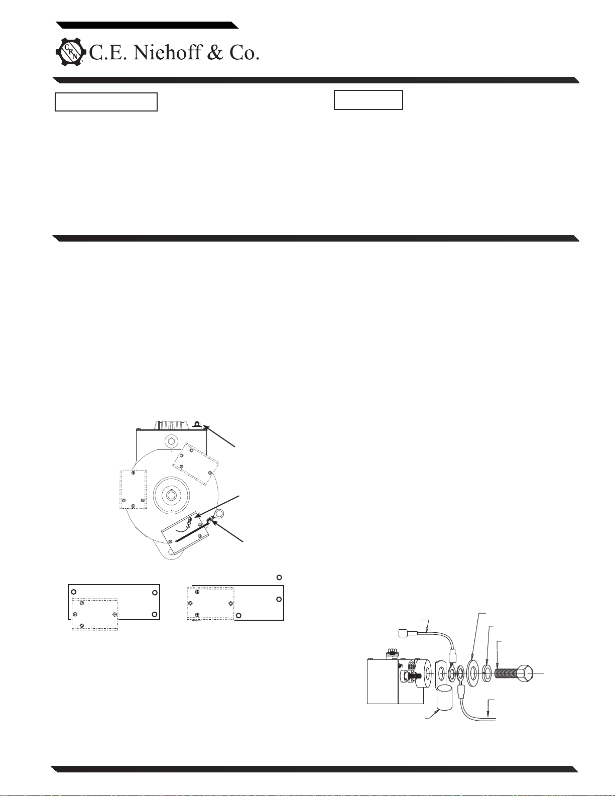
F+ terminal
1
2
3
Drive end housing cover plate
not on all units
Green ground
wire
B+ connecting
wire
A9-305 Filter Assembly is designed only to
NOTICE
reduce electromagnetic interference (EMI)
from CEN alternator/regulator to acceptable
levels as defined by Society of Automotive
Engineers (SAE) specification J1113/41. This
device will NOT reduce EMI from sources
s uch as vehi cle di gital s ystems, w irele ss lin ks ,
digital devices, antennas, poor cable routing
practice, and other electrical/electronic
devices that cause EMI. If EMI continues after
installing A9-305 per these instructions,
consult an electromagnetic compliance
(EMC) specialist to determine EMI source.
2. Install filter assembly to be connected to
B+ terminal on alternator:
a. Disconnect vehicle battery master switch or
vehicle battery cables.
b. To install unit directly on alternator:
1) Remove and discard two short screws from
selected location on alternator (see Figure 1).
2) Make sure ring terminals on filter assembly
are clean and have good contact surface.
Place filter assembly on alternator.
3) Use one new screw and lockwasher supplied
i n k i t t o s e c u r e r i n g t e r m i n a l o f g r e e n g r o u n d
wire in closest mounting hole in alternator.
Insert second screw and lockwasher in
remaining mounting hole.
4) Torque both screws to 2.3Nm / 20 lb.in.
c. To install unit in location other than alternator:
1) Set unit in mounting location. Secure green
ground wire from unit to grounded surface,
using one mounting hole in unit. Use second
mounting hole to finish securing unit to
mounting location.
d. Connect B+ connecting wire from unit to alter-
nator B+ terminal, splicing B+ wire length if
required from step 1, as shown in Figure 2.
e. Reconnect vehicle battery master switch or
vehicle battery cables.
f. Operate engine and check alternator output.
4
5
Control unit cover
Figure 1 - Filter Assembly Location on Alternator
(choose one of five locations)
Page 1 of 2
Only on units
with F+ terminal
Term i n al fr om
vehicle battery B+ cable
Figure 2 - Alternator B+ Terminal Stacking Order
Flat washer
Lock washer
B+ Terminal Bolt
(torque varies with
alternator model)
B+ connecting wire
from A9-305
II1B
Page 2

To connect filter assembly to power
source of other affected electrical/
electronic components:
1. Disconnect vehicle battery master switch or
vehicle battery cables.
2. To install unit:
a. Select location to mount filter within 12 inches
of power source on the affected component.
If location within 12 inches is not practical,
B+ connecting wire can be spliced to increase
distance up to 2 feet from power source on
component. Increased wire length reduces filter
effectiveness.
b. Secure green ground wire (see Figure 1, page 1)
from unit to grounded surface, using one
mounting hole in unit. Use second mounting hole
to finish securing unit to mounting location.
Unit MUST be connected
properly to grounded
surface directly back to
battery negative terminal.
3. Connect “B+” connecting wire from unit to component power supply, splicing B+ wire length if
required from step 2a. See Figure 2 on page 1 for
stacking order.
4. Reconnect vehicle battery master switch or vehicle
battery cables.
5. Operate engine and check component operation.
CAUTION
If you have questions about your alternator or any of t hese instructions, or if you need to locate a Factory Authori zed Service Dea ler, please contact us at:
TEL: 800.643.4633 USA and Canada • TEL: 847.866.6030 outside USA and Canada • FAX: 847.492.1242
Page 2 of 2
C. E. Niehoff & Co.• 2021 Lee Street • Evanston, IL 60202 USA
E-mail us at service@CENiehoff.com
II1B
 Loading...