

Page 1
C619, N1222, N1223, A1-607,
and A1-608 Alternators
Installation Instructions
This symbol is used to indicate
CAUTION
presence of hazards that can cause
minor property damage.
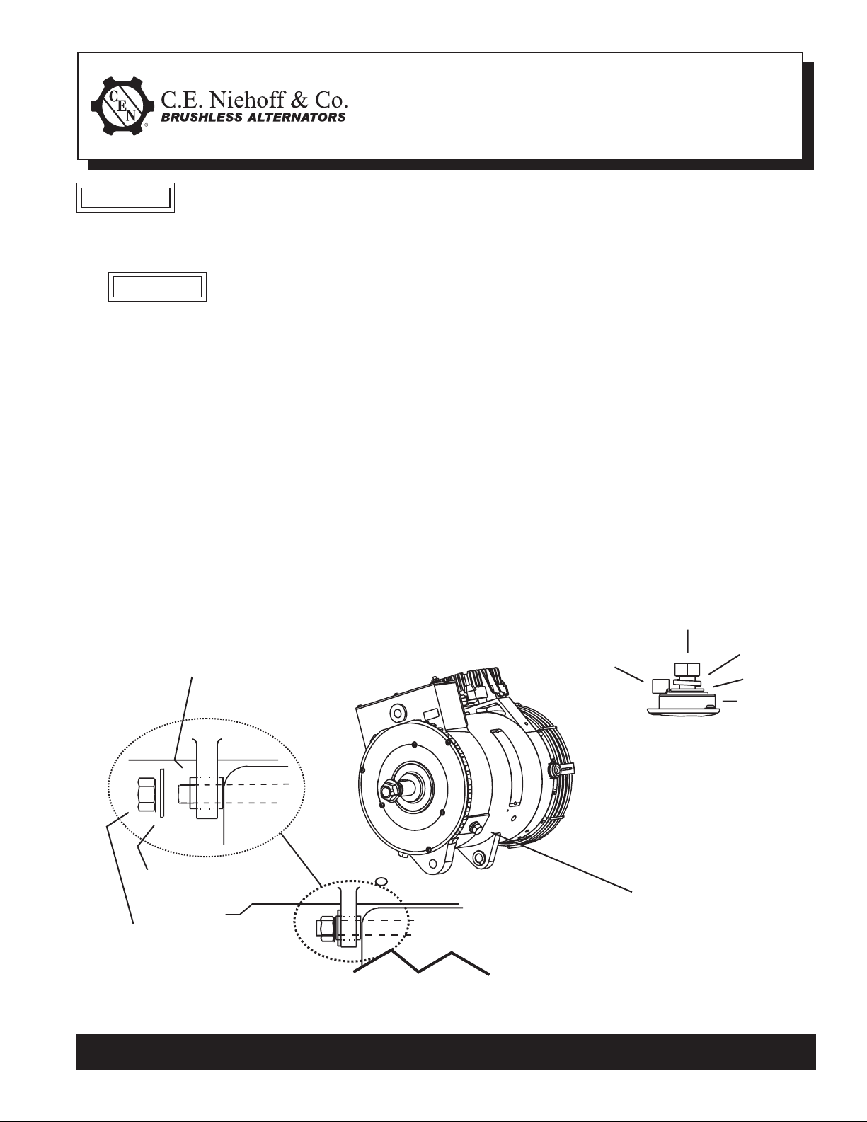
1. Install alternator as shown in Figure 1:
Slip bushing located in rear
mounting foot must be se-
CAUTION
curely tightened against
alternator mounting bracket
on engine. Failure to do so
can result in broken mounting
feet or broken upper mounting
bracket.
a. Use hardened washers between aluminum
surfaces and bolt heads and nuts.
b. OEM units are shipped with pulley, flat
washer, and locknut installed.
c. Aftermarket units are shipped with shaft
collar, flat washer, and locknut installed.
Remove and discard shaft collar. Install
pulley and furnished flat washer. Torque
locknut to 163 Nm/120 lb. ft.
d. Follow vehicle manufacturer’s
recommendations for belt tension.
2. All cabling, wiring, or conduit must be supported
within 305 mm/12 in. of termination
on alternator.
3. Choose wire gauge capable of handling
maximum alternator output with no more
than 0.2 V drop on each leg from alternator
to battery.
4. Regulator is furnished on OEM units and is
supplied separately by request with aftermarket
units. Mounting screws on regulator should be
torqued to 8.5 Nm/75 lb. in.
5. Control unit electrical connections:
a. Make sure alternator-to-regulator harness
plug is secure in regulator receptacle.
b. E stud terminal: Torque terminal nut to
2.3 Nm/20 lb. in.
c. R/P1/P2/P3/F+ stud terminals: Torque
terminal nuts to 8.5 Nm/75 lb. in.
1/2-13 bolt –
torque to 32 Nm/24 lb. ft.
Slip bushing must be tightened against
bracket — see “CAUTION” above
Battery output
cable terminal
T
Alternator B+
Terminal Stud
T
Lockwasher
Washer
T
T
Insulator
T
T
T
T
Hardened washer
12mm/0.50 Locknut –
torque to
88 Nm/65 lb. ft.
Bracket
on engine
T
B– terminal bolt
3/8-16 –
torque to
15 Nm/11 lb. ft.
Figure 1 - Alternator Installation Details
C. E. Niehoff & Co. • 2021 Lee Street • Evanston, IL 60202 Tech Services Hotline 800-643-4633
Page 1 of 1
II0076A
 Loading...