

CEMONT TF 300, TF 400, TF 400H Use And Maintenance
TF 300 / TF 400 / TF 400H
EN Safety instruction for use and maintenance - Do not destroy this manual
FR Instruction de securite d’emploi et d’entretien - Conserver ce livret d’instructions
ES Instrucciones de seguridad, empleo y mantenimiento - Conservar el presente manual
IT Istruzioni per la sicurezza nell’uso e per la manutenzione - Conservare il presente libretto
DE Betriebs-Wartungs und Sicherheitsanleitung - Das vorliegende Handbuch gut aufbewahren
PT Instrucões de segurança de utilização e de manutenção - Conserve este manual
SV Instruktioner för säkerhet, använding och underåll - Spar denna handledning
NL Veiligheidsinstructies voor gebruik en onderhoud - Bewaar deze handleiding
RO Instructiuni privind siguranta in exploatare si intretinerea - Pastrati acest manual
SK Bezpečnostné pokyny pri používaní a pri údržbe - Odložte si tento návod na použitie
CS Bezpečnostní pokyny pro používání a údržbu - Návod na používání si uchovejte
HU Használati és karbantartási biztonsági utasítások - Kerjük őrizze meg ezt a hasznsnalati utasítást
PL Instrukcje bezpieczeństwa podczas obsługi i konserwacji - Zachować niniejszą instrukcję na przyszłość
EL Οδηγιεσ ασφαλειασ κατα τη χρηση και τη συντηρηση – φυλαξτε το παρον εγχειριδιο
RU Руководство по безопасной эксплуатации и техническому обслуживанию
Cat. Nr.:
Rev.:
Date:
800035647
00
28. 10. 2008
www.airliquidewelding.com
Air Liquide Welding - 13, rue d’Epluches - BP 70024 Saint-Ouen L’Aumône

Welding Operations Services Slovakia, spol. s r.o.
Hlohovecká 6, 951 41 Nitra - Lužianky, SLOVAK REPUBLIC
MEMBER OF AIR LIQUIDE WELDING GROUP.

CONTENTS
1.0 TECHNICAL DESCRIPTION . . . . . . . . . . . . . . . . . . . . . . . . . . . . . . . . . . . . . . . . . . . . . . . . . . . . . . . . . . . . . 3
1.1 DESCRIPTION . . . . . . . . . . . . . . . . . . . . . . . . . . . . . . . . . . . . . . . . . . . . . . . . . . . . . . . . . . . . . . . . . . 3
1.2 TECHNICAL CHARACTERISTICS . . . . . . . . . . . . . . . . . . . . . . . . . . . . . . . . . . . . . . . . . . . . . . . . . . . 3
2.0 CONNECTION TO THE GENERATOR . . . . . . . . . . . . . . . . . . . . . . . . . . . . . . . . . . . . . . . . . . . . . . . . . . . . . 3
3.0 WIRE REEL INSTALLATION . . . . . . . . . . . . . . . . . . . . . . . . . . . . . . . . . . . . . . . . . . . . . . . . . . . . . . . . . . . . 3
3.1 WIRE REEL INSTALLATION . . . . . . . . . . . . . . . . . . . . . . . . . . . . . . . . . . . . . . . . . . . . . . . . . . . . . . . 3
3.2 START-UP . . . . . . . . . . . . . . . . . . . . . . . . . . . . . . . . . . . . . . . . . . . . . . . . . . . . . . . . . . . . . . . . . . . . . . 3
4.0 DESCRIPTION OF FRONT PANEL CONTROLS . . . . . . . . . . . . . . . . . . . . . . . . . . . . . . . . . . . . . . . . . . . . . 4
4.1 FRONT PANEL . . . . . . . . . . . . . . . . . . . . . . . . . . . . . . . . . . . . . . . . . . . . . . . . . . . . . . . . . . . . . . . . . . 4
5.0 BASIC INFORMATION REGARDING MIG WELDING . . . . . . . . . . . . . . . . . . . . . . . . . . . . . . . . . . . . . . . . . 4
6.0 CONNECTION AND PREPARATION OF EQUIPMENT FOR WELDING . . . . . . . . . . . . . . . . . . . . . . . . . . 4
6.1 WELDING . . . . . . . . . . . . . . . . . . . . . . . . . . . . . . . . . . . . . . . . . . . . . . . . . . . . . . . . . . . . . . . . . . . . . . 4
6.2 CARBON STEEL WELDING . . . . . . . . . . . . . . . . . . . . . . . . . . . . . . . . . . . . . . . . . . . . . . . . . . . . . . . . 5
EN
6.3 STAINLESS STEEL WELDING . . . . . . . . . . . . . . . . . . . . . . . . . . . . . . . . . . . . . . . . . . . . . . . . . . . . . . 5
6.4 ALUMINIUM WELDING . . . . . . . . . . . . . . . . . . . . . . . . . . . . . . . . . . . . . . . . . . . . . . . . . . . . . . . . . . . . 5
6.5 SPOT WELDING . . . . . . . . . . . . . . . . . . . . . . . . . . . . . . . . . . . . . . . . . . . . . . . . . . . . . . . . . . . . . . . . . 5
7.0 MIG WELDING FAULTS . . . . . . . . . . . . . . . . . . . . . . . . . . . . . . . . . . . . . . . . . . . . . . . . . . . . . . . . . . . . . . . . 5
7.1 FAULT CLASSIFICATION AND DESCRIPTION . . . . . . . . . . . . . . . . . . . . . . . . . . . . . . . . . . . . . . . . 5
8.0 GENERAL MAINTENANCE . . . . . . . . . . . . . . . . . . . . . . . . . . . . . . . . . . . . . . . . . . . . . . . . . . . . . . . . . . . . . 6
8.1 TORCH MAINTENANCE . . . . . . . . . . . . . . . . . . . . . . . . . . . . . . . . . . . . . . . . . . . . . . . . . . . . . . . . . . . 6
8.2 CONNECTING THE TORCH . . . . . . . . . . . . . . . . . . . . . . . . . . . . . . . . . . . . . . . . . . . . . . . . . . . . . . . 6
SPARE PARTS LIST. . . . . . . . . . . . . . . . . . . . . . . . . . . . . . . . . . . . . . . . . . . . . . . . . . . . . . . . . . . . . . . . . . . . . .I - XII
WIRING DIAGRAM . . . . . . . . . . . . . . . . . . . . . . . . . . . . . . . . . . . . . . . . . . . . . . . . . . . . . . . . . . . . . . . . . . . . XIII - XIV
2 EN
EN
WELDING WIRE CAN CAUSE INJURY.
Never point the torch towards the body or towards
other metals when unwinding welding wire.
TECHNICAL DESCRIPTION
1.0 TECHNICAL DESCRIPTION
1.1 DESCRIPTION
The wire feeder together with a generator form an installation that
can be used on the direct wire welding process.
Linked to generators it is able to satisfy many operative requirements.
1.2 TECHNICAL CHARACTERISTICS
Model 345A
Range of solid wires* Ø 0,6 ÷ 1,2 mm
Range of cored wires* Ø 0,8 ÷ 1,2 mm
Reel sizes Ø 300 mm
Gas**
Cooling -
Model 450A 450A H
Range of solid wires* Ø 0,6 ÷ 1,6 mm Ø 0,6 ÷ 1,6 mm
Range of cored wires* Ø 0,8 ÷ 2,4 mm Ø 0,8 ÷ 2,4 mm
Reel sizes Ø 300 mm Ø 300 mm
Gas**
Cooling -
Ar or CO2 o MIX
(max 4 bar)
* For using the entire range of wires possible, the wire rollers supplied must be supplemented with those having suitable grooves
(e.g. Knurled grooves for cored wires)
** The shielding gas used depends on the metal being welded;
see some examples in the following table:
Material to be welded Usable shielding gas
Steel CO2 or MIX (Ar + CO2)
Stainless steel MIX (Ar + O2)
Aluminium Ar
Ar or CO2 o MIX
(max 4 bar)
Ar or CO2 o MIX
(max 4 bar)
Water with 30% anti-
freeze glycol max 5 bar
7. Close the upper bridge of the wire feed unit and check that
the wire is positioned in the relative groove.
8. Connect the torch and insert the protruding wire section into
the sleeve, taking care that the control pins are fitted correctly
in the seats and the connector nut is tightened fully down.
3.2 START-UP
1. Switch on the machine
2. Set the power switch to an intermediate position.
3. Remove the nozzle and wire guide tube from the torch, press
the button (Ref. 8 - Picture 1 Page 4.) and feed the wire until
it protrudes from the front section of the torch. While feeding
wire through the torch, use the handwheel to adjust the force
that the wire pressure roller exerts on the feed roller; the setting must ensure that the welding wire moves regularly without slipping on the rollers and without deforming. Fit the torch
with a suitable wire guide tube according to the type of wire
used.
4. Secure the wire guide tube, and ensure that the diameter corresponds to the wire used.
5. Refit the gas nozzle.
6. Open the gas cylinder valve.
7. Connect the ground clamp to the workpiece on a section free
of rust, paint, grease or plastic.
IMPORTANT: IF THE WIRE FEEDER IS SUSPENDED DURING
WELDING, MAKE SURE THE WIRE FEEDER FRAME IS ISOLATED FROM THE EARTHING CIRCUIT (E.G. USE LIFTING
ROPES IN NYLON OR OTHER INSULATING MATERIAL).
THIS PRECAUTION IS INDISPENSABLE IN ORDER TO PREVENT POSSIBLE RECLOSURE OF THE WELDING CURRENT
THROUGH THE LIFTING MEANS AND THE ELECTRICAL
SYSTEM EARTHING CIRCUIT.
FAILURE TO COMPLY WITH THIS SAFETY RULE CAN RESULT IN SERIOUS DAMAGE TO THE ELECTRICAL SYSTEM
AND COMPROMISE THE TROLLEY LIFTING SYSTEM.
2.0 CONNECTION TO THE GENERATOR
1. Make sure the generator is off before carrying out this operation.
2. Connect the umbilical cord's power socket to the relative plug
placed at the back panel of the machine (insert it completely
and rotate clockwise so that it is completely blocked).
3. Connect the multiple plugs to the relative socket blocking it
with the appropriate end.
4. Connect the gas tube coming out from the cord to the cylinder
pressure reducer.
3.0 WIRE REEL INSTALLATION
3.1 WIRE REEL INSTALLATION
1. Put the wire reel in the relative spool so that the two rotate together.
2. Adjust the spool brake by means of the central nut on the latter, so that the reel rotates easily (on some spools the adjustment nut is not visible, but is accessible after withdrawing the
retainer tab).
3. Open the upper bridge of the wire feed unit
4. Check that the rollers are suited to the diameter of the wire to
be used; otherwise change.
5. Straighten an end section of the wire and cut it.
6. Pass the wire over the two lower rollers and insert in the torch
connector tube until it protrudes from the latter by approx. 10 cm.
3 EN
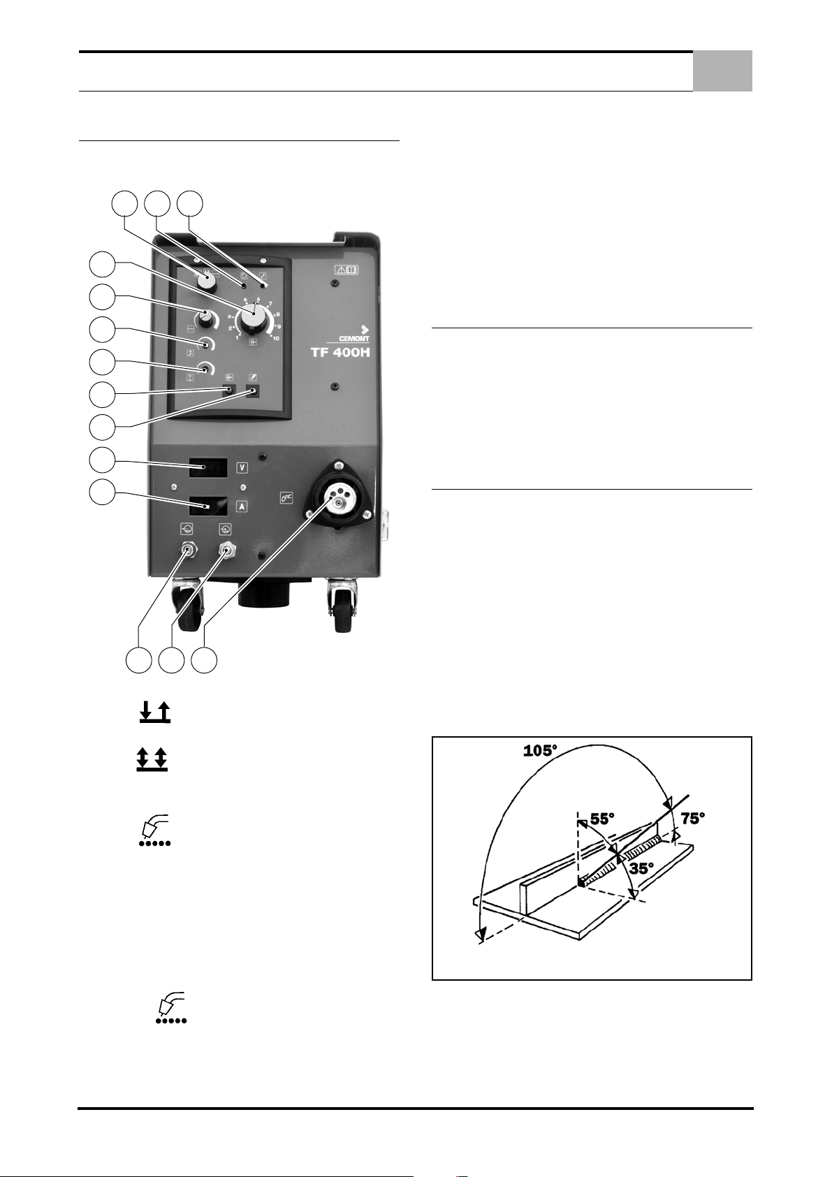
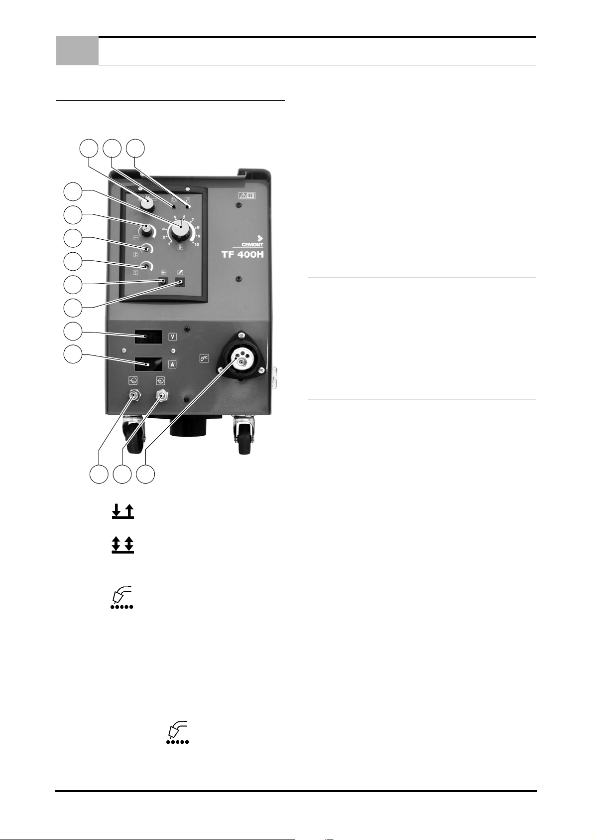
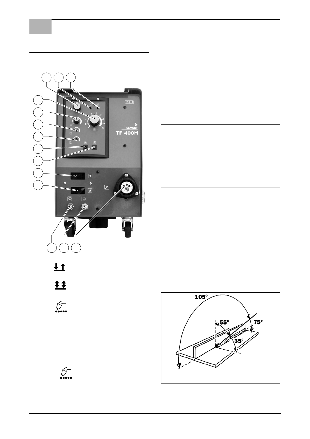
DESCRIPTION OF FRONT PANEL CONTROLS
3
2
1
4
5
6
7
8
9
14
15
10
17
16
EN
4.0 DESCRIPTION OF FRONT PANEL CON-
TROLS
4.1 FRONT PANEL
Picture 1.
1 - Welding system selector:
In position (2 stroke welding) press the torch button to
start welding, and release to stop.
practice, at the end of welding, if this time is too short, the wire remains stuck in the bath or protrudes too far from the torch contact
tube; otherwise, if the control time is too long, the wire remains
stuck in the torch contact tube, often causing damage to the latter.
8 - Advance wire button (without "current")
9 - Gas output test button
10 - Euro torch connector
14 - Voltmeter
15 - Ammeter
16 - Cooling water delivery connection (blue)
17 - Cooling water return connection (red)
5.0 BASIC INFORMATION REGARDING MIG
WELDING
MIG WELDING PRINCIPLES
MIG welding is autogenous, i.e. it permits welding of pieces made
of the same metal (mild steel, stainless steel, aluminium) by fusion, while granting both physical and mechanical continuity. The
heat required for melting is generated by an electric arc that
strikes between the wire (electrode) and the piece to be welded.
A shield gas protects both the arc and the molten metal from the
atmosphere.
6.0 CONNECTION AND PREPARATION OF
EQUIPMENT FOR WELDING
CONNECT WELDING ACCESSORIES CAREFULLY TO AVOID
POWER LOSS OR LEAKAGE OF DANGEROUS GASES.
Carefully follow the safety standards
N.B. DO NOT ADJUST SWITCHES during welding operations to
avoid damage to the equipment.
CHECK THAT GAS IS DELIVERED FROM THE NOZZLE AND
ADJUST FLOW BY MEANS OF THE PRESSURE REDUCER
VALVE.
CAUTION: SCREEN GAS FLOW WHEN OPERATING IN OUTDOOR OR VENTILATED SITES; WELDING OPERATIONS
MAY NOT BE PROTECTED DUE TO DISPERSION OF INERT
SHIELDING GASES.
6.1 WELDING
1. Open the gas cylinder and regulate gas outlet flow as re-
quired. Fit the earth clamp on a part of the welding piece without any paint, plastic or rust.
In position (4 stroke welding) press the torch button to deliver gas; on release, wire feed and current are activated; press
again to stop wire feed and current and release to shut off the gas
supply.
In position (spot welding) the welder operates in timed
mode; press the torch button to start the welding phase, which
stops automatically after the time interval as set on the timer potentiometer (Ref. 5 - Picture 1 Page 4.).
2 - Machine ON indicator lamp
3 - Machine overheating indicator lamp or defect on the water
cooling PCB.
4 - Wire feed speed control -potentiometer
5 - Spot welding time control potentiometer, from 0.3 to 10
seconds (operating only with selector (Ref. 1 - Picture 1 Page 4.)
set to position
6 - Wire feed motor acceleration time control potentiometer.
7 - Wire burn-off potentiometer. Time during which the welding
power is maintained after regular release of the torch button. In
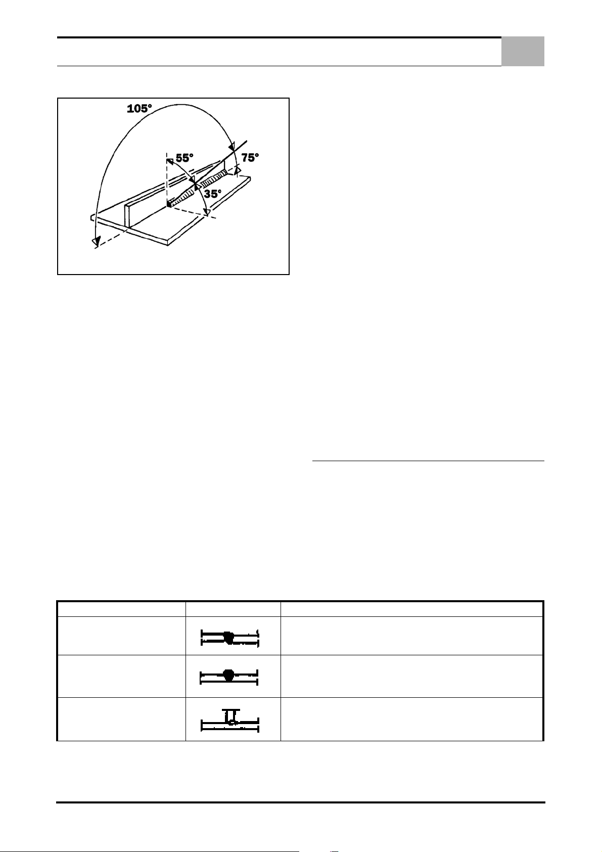
For optimal welding, keep the torch in the same direction as
the wire feed, as illustrated in figure.
2. Select the welding current by means of switches (Ref. 11 -
Picture 1 Page 4.); bear in mind that the greater the welding
thickness, the more power is required. The first switch setting
is suitable for minimum thickness welding.Also take into account that each setting features a specific wire drive speed
which can be selected by means of adjustment knob (Ref. 4
- Picture 1 Page 4.).
4 EN
EN
MIG WELDING FAULTS
6.2 CARBON STEEL WELDING
For MIG welding, proceed as follows:
1. Use a binary shielding gas (commonly a AR/CO2 mixture
with percentages ranging from 75-80% of Argon and from 2025% of CO2), or ternary mixtures such as AR/CO2/O2.
These gases provide welding heat and a uniform and compact bead, although penetration is low. Use of carbon dioxide
(MAG) as a shielding gas achieves a thin and well-penetrated bead but ionisation of the gas may impair arc stability.
2. Use a wire feed of the same quality of that of the steel for
welding. Always use good quality wire; welding with rusty
wires can cause welding defects.
In general the applicable current range for wire use is:
- Ø wire mm x 100 = minimum Amps.
- Ø wire mm x 200 = minimum Amps.
Example: Ø filo 1.2 mm= minimum Amps 120 mm/maximum
Amps 240.
The above range is used with binary AR/CO2 gas mixtures
and with short-circuiting transfer (SHORT).
3. Do not weld parts where rust, oil or grease is present.
4. Use a torch suited to welding current specifications
5. Periodically check that the earth clamp pads are not damaged and that the welding cables (torch and earth) are not cut
or burnt which could impair efficiency.
6.3 STAINLESS STEEL WELDING
MIG Welding of 300 series (austenitic) stainless steel must be carried out with a shielding gas that has a high Argon content and a
small percentage of O2 to stabilise the arc. The most commonly
used mixture is AR/O2 98/2.
- Never use CO2 or AR/CO2 mixtures.
- Never touch the wire.
FAULT APPEARANCE CAUSE AND REMEDY
The filler material used must be of a higher quality than the base
material and the welding zone must be completely clean.
6.4 ALUMINIUM WELDING
To MIG weld aluminium, use the following:
1. 100% Argon shielding gas.
2. Filler wire with a composition suited to the base welding material. To weld ALUMAN and ANTICORODAL use 3-5% silicon wire. To weld PERALUMAN and ERGAL use 5%
magnesium wire.
3. Use a torch designed for aluminium welding.
6.5 SPOT WELDING
This type of welding is used for spot welding two overlapping
sheets, and requires the use of a special gas nozzle.
Fit the spot welding gas nozzle, press it against the piece to be
welded. Press the torch button; note that the welder will eventually
detach from the piece. This time period is fixed by the TIMER control (Ref. 5 - Picture 1 Page 4.), and must be set depending on the
thickness of the material.
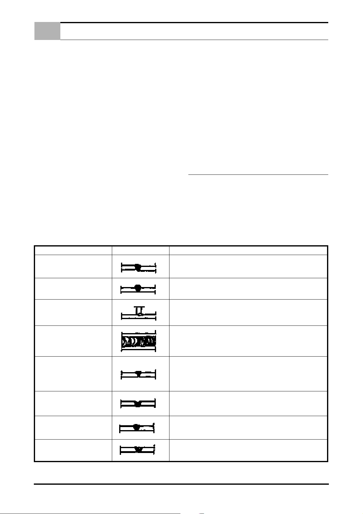
7.0 MIG WELDING FAULTS
7.1 FAULT CLASSIFICATION AND DESCRIPTION
MIG welds may be affected by various defects, which are important to identify. These faults do not differ in form or nature from
those encountered during manual arc welding with coated electrodes. The difference between the two applications lies rather in
the frequency of defects: porosity, for example, is more common
in MIG welding, while inclusion of slag is only encountered in
welding with coated electrodes.
The causes and prevention of faults are also quite different.
The following table illustrates the various faults.
UNEVEN LEVEL
EXCESS THICKNESS
INSUFFICIENT METAL
OXIDISED BEAD
INSUFFICIENT PENETRATION
OVER PENETRATION
LACK OF FUSION
- Poor preparation.
- Align edges and hold during spot welding.
- No-load voltage or welding speed too low.
- Incorrect torch inclination.
- Wire diameter too large.
- Welding speed too high.
- Welding voltage too low for welding application.
- Weld in the channel if using a long arc.
- Regulate voltage.
- Wire is bent or over-protruding from the wire guide tube.
- Incorrect wire feed speed.
- Incorrect torch inclination.
- Irregular or insufficient distance.
- Wire guide tube worn.
- Wire speed too slow for voltage used or for welding speed.
- Wire speed too high.
- Incorrect torch inclination.
- Excessive distance.
- Distance too short.
- Rough out or grind the weld, then repeat.
CHANNELS
- Welding speed too high.
(This fault is easily detected on sight by the welder, and should be corrected immediately.)
5 EN
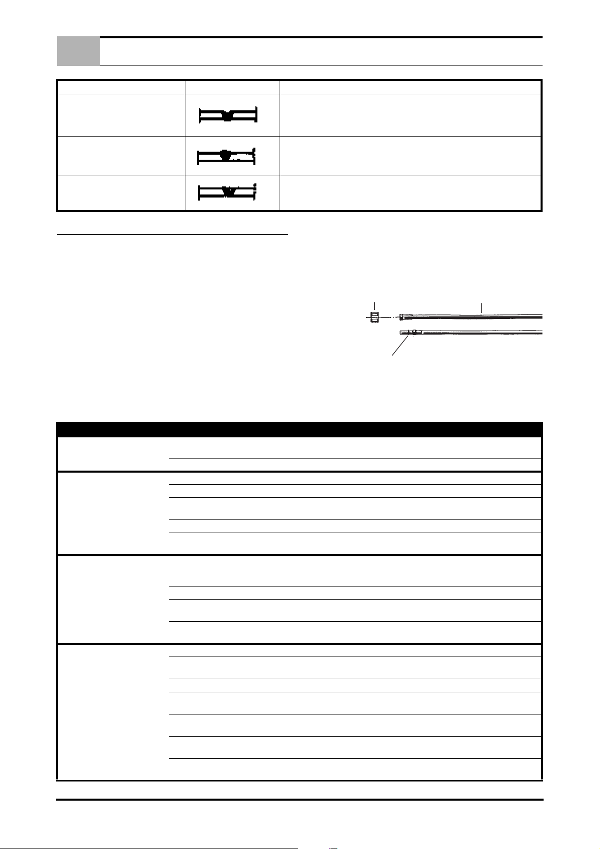
GENERAL MAINTENANCE
19
21
18
20
22
EN
8.0 GENERAL MAINTENANCE
8.2 CONNECTING THE TORCH
Prior to connecting the torch, make sure that the wire sheath (18)
DISCONNECT THE POWER SOURCE FROM THE MAINS BE-
is suited to the diameter of the wire used:
FORE PERFORMING ANY MAINTENANCE WORK.
Every 5-6 months, remove accumulated dust from the inside of
the welding unit with a jet of dry compressed air (after removing
side panels).
BE EXTREMELY CAREFUL TO AVOID BENDING MOVEMENTS, WHICH COULD DAMAGE AND CHOKE THE TORCH.
NEVER MOVE THE POWER SOURCE BY PULLING THE
TORCH.
PERIODICALLY CHECK THE CONDITION OF THE TORCH,
WHICH IS THE PART MOST SUBJECT TO WEAR.
8.1 TORCH MAINTENANCE:
- BLUE Ø 1.5 for wire Ø 0,6- 0.8 mm.
- RED Ø 2.0 for wire Ø 1 - 1.2 mm.
(Wire sheath colour for steel wire).
1. GAS NOZZLE: periodically apply welding spray and clean
nozzle interior of residue.
2. WIRE GUIDE TUBE: check the wire passage of the tube for
wear. Replace as necessary.
TYPE OF BREAKDOWN POSSIBLE CAUSES CHECKS AND REMEDIES
No functions operate.
Irregular wire feed. Insufficient spring pressure. Try tightening regulating knob.
Irregular wire feed.
Reduced welding power. Earth cable not connected.
Porous or spongy welds. No gas. Check presence of gas and gas supply pressure.
Porous or spongy welds. Faulty pressure regulator.
Gas supply does not switch off. Worn or dirty solenoid valve. Dismantle solenoid; clean hole and obturator.
Presslng torch trigger produces no
result.
Faulty power cord (one or more phases disconnected).
Blown fuse. Renew.
Wire-guide sheath blocked. Renew.
Wrong race - unsuitable for wire, or excessively
worn.
Braking on coil excessive. Loosen brake using adjusting screw.
Oxidized, poorly wound, poor quality wire, with
tangled or overlapping coils, etc.
Detached or loose connection on switches Check, tighten or renew, as necessary.
Faulty contactor
Faulty rectifier. Visually check for signs of burn-out; if present, renew rectifler.
Draughts in welding area. Use a suitable screen. Increase gas delivery pressure if necessary.
Ciogged holes in diffuser. Clear clogged holes using compressed air.
Gas leakage due to rupture in supply hoses.
Solenoid valve blocked.
Poor quality gas or wire.
Faulty torch trigger, disconnected or broken
control cables.
Blown fuse. Renew using a fuse of the same rating.
Faulty power switch.
Faulty electronic circuit. Renew circuit.
Check and remedy.
Turn roller over or change it.
Remedy by removing defective coils. If problem persists, change the
wire reel.
Check that the power cord is in good condition and make sure that the
ground clamps are flrmly fixed to the works piece, which must be free
of rust, grease and paint.
Check the state of the contacts and the mechanical efficiency of the
contactor
Check and renew faulty component.
Check solenoid operation an electrical connection.
Check operation by removing the hose connecting the pressure regulator to the power source.
Gas must be extra-dry; change the cylinder or use a different type
wire.
Remove the torch connection plug and short-circuit the poles; if the
machine operates properly, check the cables and the torch trigger.
Clean with compressed air. Ensure that wires are tightly secured; renew switch if necessary.
6 EN

FR
1.0 DESCRIPTION DONNEES TECHNIQUES . . . . . . . . . . . . . . . . . . . . . . . . . . . . . . . . . . . . . . . . . . . . . . . . . . 2
1.1 DESCRIPTION . . . . . . . . . . . . . . . . . . . . . . . . . . . . . . . . . . . . . . . . . . . . . . . . . . . . . . . . . . . . . . . . . . 2
1.2 DONNÉES TECHNIQUES . . . . . . . . . . . . . . . . . . . . . . . . . . . . . . . . . . . . . . . . . . . . . . . . . . . . . . . . . 2
2.0 CONNEXION AU GENERATEUR . . . . . . . . . . . . . . . . . . . . . . . . . . . . . . . . . . . . . . . . . . . . . . . . . . . . . . . . . 2
3.0 INSTALLATION DE LA BOBINE DE FIL . . . . . . . . . . . . . . . . . . . . . . . . . . . . . . . . . . . . . . . . . . . . . . . . . . . 2
3.1 INSTALLATION DE LA BOBINE DE FIL . . . . . . . . . . . . . . . . . . . . . . . . . . . . . . . . . . . . . . . . . . . . . . . 2
3.2 MISE EN SERVICE . . . . . . . . . . . . . . . . . . . . . . . . . . . . . . . . . . . . . . . . . . . . . . . . . . . . . . . . . . . . . . . 2
4.0 DESCRIPTION DES COMMANDES SUR LE PANNEAU FRONTAL . . . . . . . . . . . . . . . . . . . . . . . . . . . . . 3
4.1 PANNEAU ANTERIEUR . . . . . . . . . . . . . . . . . . . . . . . . . . . . . . . . . . . . . . . . . . . . . . . . . . . . . . . . . . . 3
5.0 NOTIONS DE BASE SUR LE SOUDAGE MIG . . . . . . . . . . . . . . . . . . . . . . . . . . . . . . . . . . . . . . . . . . . . . . . 3
6.0 RACCORDEMENTS ET PRÉPARATION DE L’ÉQUIPEMENT POUR LE SOUDAGE . . . . . . . . . . . . . . . . 3
6.1 SOUDAGE . . . . . . . . . . . . . . . . . . . . . . . . . . . . . . . . . . . . . . . . . . . . . . . . . . . . . . . . . . . . . . . . . . . . . . 3
6.2 SOUDAGE DES ACIERS AU CARBONE . . . . . . . . . . . . . . . . . . . . . . . . . . . . . . . . . . . . . . . . . . . . . . 4
SOMMAIRE
6.3 SOUDAGE DES ACIERS INOXYDABLES . . . . . . . . . . . . . . . . . . . . . . . . . . . . . . . . . . . . . . . . . . . . . 4
6.4 SOUDAGE DE L’ALUMINIUM . . . . . . . . . . . . . . . . . . . . . . . . . . . . . . . . . . . . . . . . . . . . . . . . . . . . . . . 4
6.5 BOUTONNAGE . . . . . . . . . . . . . . . . . . . . . . . . . . . . . . . . . . . . . . . . . . . . . . . . . . . . . . . . . . . . . . . . . . 4
7.0 DÉFAUTS DES SOUDURES MIG . . . . . . . . . . . . . . . . . . . . . . . . . . . . . . . . . . . . . . . . . . . . . . . . . . . . . . . . . 4
7.1 CLASSIFICATION ET DESCRIPTION DES DÉFAUTS . . . . . . . . . . . . . . . . . . . . . . . . . . . . . . . . . . . 4
8.0 ENTRETIEN ORDINAIRE . . . . . . . . . . . . . . . . . . . . . . . . . . . . . . . . . . . . . . . . . . . . . . . . . . . . . . . . . . . . . . . 5
8.1 PRINCIPALES OPÉRATIONS . . . . . . . . . . . . . . . . . . . . . . . . . . . . . . . . . . . . . . . . . . . . . . . . . . . . . . 5
9.0 RACCORDEMENT DE LA TORCHE . . . . . . . . . . . . . . . . . . . . . . . . . . . . . . . . . . . . . . . . . . . . . . . . . . . . . . . 5
PIÈCES DÉTACHÉES . . . . . . . . . . . . . . . . . . . . . . . . . . . . . . . . . . . . . . . . . . . . . . . . . . . . . . . . . . . . . . . . . . . .I - XII
SCHÉMA ÉLECTRIQUE . . . . . . . . . . . . . . . . . . . . . . . . . . . . . . . . . . . . . . . . . . . . . . . . . . . . . . . . . . . . . . .XIII - XIV
1 FR

DESCRIPTION DONNEES TECHNIQUES
LE FIL DE SOUDAGE PEUT PROVOQUER DES
BLESSURES PAR PERFORATION.
Pendant le déroulement du fil, ne pas pointer la
torche vers soi-même ou vers toute autre personne, ainsi que vers toute surface métallique.
FR
1.0 DESCRIPTION DONNEES TECHNIQUES
1.1 DESCRIPTION
Le de l'alimentateur de fil, avec un générateur, un système prêt
pour être utilisé dans le processus de soudure à fil continu.
Avec les générateurs il est en mesure de satisfaire plusieurs exigences opérationnelles.
1.2 DONNÉES TECHNIQUES
Modèle 345A
Gamme fils pleins* Ø 0,6 ÷ 1,2 mm
Gamme fils enrobés* Ø 0,8 ÷ 1,2 mm
Tailles bobines Ø 300 mm
Gaz**
Modèle -
Modèle 450A 450A H
Gamme fils pleins* Ø 0,6 ÷ 1,6 mm Ø 0,6 ÷ 1,6 mm
Gamme fils enrobés* Ø 0,8 ÷ 2,4 mm Ø 0,8 ÷ 2,4 mm
Tailles bobines Ø 300 mm Ø 300 mm
Gaz**
Modèle -
Ar or CO2 o MIX
(max 4 bar)
* Pour utiliser toute la gamme de fils possible il est nécessaire de
compléter la fourniture de rouleaux débobineurs par les rouleaux
présentant une gorge adaptée (ex. Gorges rainurées pour fils enrobés
** Le gaz de protection à utiliser dépend du métal à souder (voir
exemples table suivante):
Ar or CO2 o MIX
(max 4 bar)
Ar or CO2 o MIX
(max 4 bar)
Eau 30% glycole anti-
gel max 5 bar
4. S'assurer que les rouleaux sont appropriés au diamètre du fil
que l'on veut utiliser. S'il n'en est pas ainsi, les remplacer.
5. Redresser une partie de l'extrémité du fil et la couper.
6. Faire passer le fil au-dessus des deux rouleaux inférieurs et
l'enfiler dans le tube de fixation du chalumeau, de façon à ce
qu'il en sorte d'environ 10 cm.
7. Refermer le pont supérieur du groupe d'entraînement en
s'assurant que le fil est bien positionné dans la gorge prévue
à cet effet.
8. Raccorder le chalumeau en enfilant dans la gaine le morceau
de fil qui dépasse de la fixation. Prêter attention aux chevilles
de commande en les dirigeant dans les logements prévus à
cet effet et visser à fond la bague de raccordement.
3.2 MISE EN SERVICE
1. Allumer la machine.
2. Mettre le commutateur de puissance sur une position intermédiaire.
3. Enlever la buse et le bec de passage du fil du chalumeau et,
en appuyant sur le bouton (Ref. 8 - Figure 1 Pag. 3.), faire
glisser le fil jusqu'à ce qu'il ne sorte plus de la partie antérieure de ce dernier. Pendant l'introduction du fil dans le chalumeau, au moyen du volant, régler la pression que le
rouleau presse-fil doit exercer sur le rouleau d'entraînement,
de façon à ce que le fil de soudage avance régulièrement
sans patiner sur les rouleaux et sans se déformer. Munir le
chalumeau d'un bec de passage du fil approprié en fonction
du fil utilisé.
4. Revisser le bec de passage du fil en veillant à ce qu'il soit
d'un diamètre approprié au fil utilisé.
Matériel à souder Gaz de protection utilisable
Acier CO2 or MIX (Ar + CO2)
Acier inox MIX (Ar + O2)
Aluminium Ar
2.0 CONNEXION AU GENERATEUR
1. Avant d’exécuter cette opération s’assurer que le générateur
soit éteint
2. Relier la prise de puissance du cordon ombilical à la prise relative placée sur le panneau postérieur de la machine (l’insérer complètement et la tourner en sens horaire jusqu’au
blocage complet).
3. Relier la fiche multiple à la prise relative en la bloquant avec
la fermeture appropriée
4. Relier le tube du gaz qui sort du cordon au réducteur de pression de la bouteille.
3.0 INSTALLATION DE LA BOBINE DE FIL
3.1 INSTALLATION DE LA BOBINE DE FIL
1. Mettre la bobine de fil dans le rouleau prévu à cet effet, de
façon à ce qu'ils tournent tous les deux ensemble.
2. Régler le frein du rouleau en agissant sur l'écrou central de
celui-ci, de façon à ce qu'il soit possible de faire tourner la bobine assez facilement (dans certains rouleaux, l'écrou de réglage n'est visible qu'en retirant vers l'extérieur le nez de
blocage).
3. Ouvrir le pont supérieur du groupe d'entraînement.
5. Remonter la buse du gaz.
6. Ouvrir le robinet de la bouteille de gaz.
7. Raccorder la pince de masse à la pièce à souder, dans un
point ne présentant aucune trace de rouille, de peinture, de
graisse ou de plastique.
ATTENTION: EN CAS D'UTILISATION DE L'ALIMENTATEUR
DE FIL SUSPENDU PENDANT LE TRAVAIL DE SOUDAGE,
S'ASSURER QUE LE CHÂSSIS DE L'ALIMENTATEUR EN FIL
SOIT ISOLÉ DU CIRCUIT DE MISE À LA TERRE (UTILISER
PAR EXEMPLE DES CÂBLES DE LEVAGE EN NYLON OU AUTRE MATÉRIEL ISOLANT). CETTE PRÉCAUTION EST INDISPENSABLE AFIN D'ÉVITER LA FERMETURE DU COURANT
DE SOUDAGE PAR LES MOYENS DE LEVAGE ET LE CIRCUIT DE MISE À LA TERRE DE L'INSTALLATION ÉLECTRIQUE.
LE NON RESPECT DE CETTE NORME DE SÉCURITÉ PEUT
PROVOQUER DE SÉRIEUX DOMMAGES À L'INSTALLATION
ÉLECTRIQUE ET COMPROMETTRE LE SYSTÈME DE LEVAGE DU CHARIOT.
2 FR
FR
3
2
1
4
5
6
7
8
9
14
15
10
17
16
DESCRIPTION DES COMMANDES SUR LE PANNEAU FRONTAL
4.0 DESCRIPTION DES COMMANDES SUR LE
PANNEAU FRONTAL
4.1 PANNEAU ANTERIEUR
Figure 1.
6 - Potentiomètre de réglage du temps d'accélération du moteur d'entraînement du fil.
7 - Potentiomètre de brûlure du fil de sou-dage. Temps pen-
dant lequel est maintenue la puissance de soudage après avoir
relâché le bouton de la torche. Dans la pratique, si à la fin du soudage, ce temps est trop court, le fil reste collé dans le bain ou il
ressort trop du petit tube de contact du chalumeau. En revanche,
si le temps est trop long, le fil colle au petit tube de contact du chalumeau et l'endommage souvent.
8 - Bouton d’avancement du fil (sans courant)
9 - Bouton d’essai de sortie du fil
10 - Attache Europeenne
14 - Voltmètre
15 - Ampèremètre
16 - Attache refoulement eau de refroidissement (bleu)
17 - Attache retour eau de refroidissement (rouge)
5.0 NOTIONS DE BASE SUR LE SOUDAGE MIG
PRINCIPE DU SOUDAGE MIG
Le soudage MIG est un soudage autogène, c’est à dire qu’il permet d’unir, par fusion, deux métaux de même nature (acier doux,
inox, aluminium) en assurant la continuité mécanique et physique
du matériau. La chaleur nécessaire à la fusion des pièces à assembler est fournie par un arc électrique qui jaillit entre le fil (électrode) et la pièce à souder. L’arc et le bain de fusion sont protégés
de l’air ambiant par la présence d’un gaz de protection.
1 - Sélecteur du système de soudage:
Sur la position (2 temps) en appuyant sur le bouton chalumeau, on peut commencer à souder; en le relâchant, on arrête.
Sur la position (4 temps) en appuyant sur le bouton chalumeau, du gaz sort; en le relâchant, le fil et le courant partent. En
y appuyant à nouveau, le fil et le courant s'arrêtent et, en le relâchant, le gaz s'arrête.
Sur la position (soudure par points) la soudeuse fonctionne en mode temporisé; en appuyant sur le bouton chalumeau, la
phase de soudage commence et elle cesse automatiquement à la
fin du temps établi avec le potentiomètre du temporisateur (Ref. 5
- Figure 1 Pag. 3.).
2 - Voyant Machine allumée
3 - Voyant Machine en surchauffe ou anomalie sur réfroidis-
sement H2O.
4 - Potentiomètre d'ajustement de la vitesse du fil
5 - Potentiomètre de réglage du temps de pointage, de 0,3 à 10
secondes (il fonctionne uniquement avec le sélecteur (Ref. 1 - Figure 1 Pag. 3.) sur la position
6.0 RACCORDEMENTS ET PRÉPARATION DE
L’ÉQUIPEMENT POUR LE SOUDAGE
RACCORDER SOIGNEUSEMENT LES ACCESSOIRES AFIN
D’ÉVITER TOUTE PERTE DE PUISSANCE OU FUITE DE GAZ
DANGEREUSE.
RESPECTER SCRUPULEUSEMENT LES NORMES DE SÉCURITÉ.
N.B.: NE PAS ACTIONNER LES COMMUTATEURS en cours de
soudage, cela pourrait endommager l’appareil.
Contrôler la sortie du gaz et en régler le débit au moyen du réducteur de pression.
ATTENTION: EN CAS DE TRAVAIL À L’EXTÉRIEUR OU DE
PRÉSENCE DE COURANTS D’AIR, PROTÉGER LE FLUX DE
GAZ QUI RISQUERAIT SINON D’ÊTRE DÉVIÉ ET DE NE PLUS
OFFRIR UNE PROTECTION SUFFISANTE.
6.1 SOUDAGE
1. Ouvrir le robinet de la bouteille de gaz et régler le débitmètre
en fonction des conditions de travail. Fixer la pince de masse
3 FR
DÉFAUTS DES SOUDURES MIG
FR
sur la pièce à souder à un emplacement exempt de peinture,
de plastique ou de rouille.
Pour un soudage correct, respecter l’inclinaison et l’avance
de la torche mentionnées à la figure.
2. Régler le courant de soudage en agissant sur les commutateur (Ref. 11 - Figure 1 Pag. 3.) en tenant compte du fait que
plus l’épaisseur des pièces à souder est importante, plus forte est la puissance requise. Les premières positions des
commutateurs correspondent au soudage de petites épaisseurs. Tenir compte aussi du fait qu’à chaque position sélectionnée correspond une vitesse de fil différente, réglable au
moyen du potentiomètre (Ref. 4 - Figure 1 Pag. 3.).
6.2 SOUDAGE DES ACIERS AU CARBONE
Pour le soudage MIG de ces métaux, il est nécessaire de:
1. Utiliser un gaz de protection à composition binaire, en général Ar/CO2 dans des proportions allant de 75 à 80% d’Argon
et 25 à 20% de CO2, ou bien à composition ternaire telle que
Ar/CO2/O2. Ces gaz donnent chaleur au soudage et il en résulte un cordon bien raccordé et esthétique, par contre la pénétration est relativement faible. En utilisant de l’anhydride
carbonique (MAG) comme gaz de protection, le cordon obtenu sera étroit et bien pénétré, mais l’ionisation du gaz influencera sur la stabilité de l’arc.
2. Utiliser un fil d’apport de même nature que l’acier à souder. Il
est important de n’utiliser que des fils de bonne qualité en
évitant de souder avec des fils rouillés qui peuvent provoquer
des défauts de soudage. En règle générale, les fils s’utilisent
dans les plages d’intensité suivantes:
- Ø fil (mm) x 100 = Courant min. (Ampères)
- Ø fil (mm) x 200 = Courant max. (Ampères)
Exemple: Ø fil = 1,2 mm : Courant de soudage: 120 A min. /
240 A max. Ceci avec des mélanges Ar/CO2 et transfert en
court-circuit (SHORT).
3. Éviter de souder sur les pièces rouillées ou présentant des
taches d’huile ou de graisse.
4. Utiliser une torche proportionnée au courant de soudage.
DÉFAUT ASPECT CAUSE ET REMÈDE
5. Vérifier régulièrement que les mors de la pince de masse ne
soient pas détériorés et que les câbles (torche et masse) ne
soient pas entaillés ou brûlés, ce qui en diminuerait l’efficacité.
6.3 SOUDAGE DES ACIERS INOXYDABLES
Le soudage MIG des aciers inoxydables de la série 300 (austénitiques) doit être effectué sous protection de gaz à haute teneur en
Argon, avec un faible pourcentage d’O2 pour garantir la stabilité
de l’arc. Le mélange le plus couramment utilisé est Ar/O2 98/2.
- Ne pas utiliser de CO2 ou de mélange Ar/CO2.
- Ne pas toucher le fil avec les mains.
Les fils d’apport devront être de qualité supérieure à celle du métal à souder et la zone de soudage doit être soigneusement nettoyée.
6.4 SOUDAGE DE L’ALUMINIUM
Pour le soudage de l’aluminium, il est nécessaire d’utiliser:
1. De l’Argon à 100% comme gaz de protection.
2. Un fil d’apport de composition adéquate pour le métal de
base à souder. Pour le soudage de l’ALUMAN et de l’ANTICORODAL, utiliser un fil contenant 3 à 5% de silicium. Pour
le soudage du PERALUMAN et de l’ERGAL, utiliser un fil
contenant 5% de magnésium.
3. Une torche équipée pour le soudage de l’aluminium.
6.5 BOUTONNAGE
Ce mode particulier de soudage, qui réalise l’assemblage par
points de deux tôles superposées, requiert une buse gaz spéciale.
Monter la buse spéciale, l’appuyer sur la pièce à souder et la
maintenir en pression. Actionner et maintenir la gâchette de la torche. Au bout d’un certain temps, le soudage s’arrête automatiquement. Ce temps est déterminé par le temporisateur TIMER (Ref.
5 - Figure 1 Pag. 3.) qui doit être réglé en fonction de l’épaisseur
des tôles à souder.
7.0 DÉFAUTS DES SOUDURES MIG
7.1 CLASSIFICATION ET DESCRIPTION DES DÉFAUTS
Les soudures obtenues par le procédé MIG peuvent présenter divers défauts, il est donc important de les identifier. Ces défauts
sont semblables, par leur forme ou leur nature, à ceux rencontrés
dans le soudage manuel à l’arc avec baguettes enrobées. La différence essentielle entre ces deux procédés réside dans le fait
que la fréquence des défauts est différente; les porosités, par
exemple, sont plus fréquentes en soudage MIG tandis que les inclusions de laitier ne se rencontrent que dans le soudage à la baguette enrobée.
Le tableau suivant résume les divers cas.
DÉNIVELLATION
ÉPAISSEUR EXCESSIVE
MANQUE DE MÉTAL
- Mauvaise préparation.
- Aligner les bords et les maintenir pendant le soudage (pointage).
- Tension à vide trop faible.
- Vitesse de soudage trop lente.
- Mauvaise inclinaison de la torche.
- Diamètre de fil trop fort.
- Vitesse de soudage trop élevée.
- Tension trop faible par rapport à la vitesse de soudage adoptée.
4 FR

FR
19
21
18
20
22
DÉFAUT ASPECT CAUSE ET REMÈDE
ENTRETIEN ORDINAIRE
CORDON AYANT
UN ASPECT OXYDÉ
MANQUE DE PENETRATION
PÉNÉTRATION EXCESSIVE
FUSION TROP FAIBLE
GORGE
8.0 ENTRETIEN ORDINAIRE
METTRE LE GÉNÉRATEUR HORS TENSION AVANT D’EFFECTUER QUELQUE INTERVENTION QUE CE SOIT.
Enlever périodiquement (tous les 5/6 mois) la poussière accumulée à l’intérieur du générateur en utilisant un jet d’air comprimé
(après avoir ôté les panneaux latéraux).
IL EST RECOMMANDÉ D’ÉVITER LES PLIAGES QUI POURRAIENT CAUSER L’ÉCRASEMENT DE LA GAINE DE LA
TORCHE ET DE NE JAMAIS DÉPLACER LE POSTE EN TIRANT SUR LA TORCHE.
CONTRÔLER PÉRIODIQUEMENT L’ÉTAT DE LA TORCHE,
ÉTANT DONNÉ QU’ELLE EST LA PARTIE LA PLUS SOUMISE
À USURE.
8.1 PRINCIPALES OPÉRATIONS
1. BUSE GAZ: pulvériser régulièrement un produit anti-collage
et nettoyer la partie interne de toutes les éclaboussures de
métal incrustées.
2. TUBE CONTACT: Contrôler que le diamètre du trou de passage du fil ne se soit par élargi par suite d’usure. Dans ce
cas, remplacer le tube contact.
- Souder dans une rainure si on travaille avec un arc long.
- Régler la tension de soudage.
- Fil plié ou trop de longueur de fil libre à la sortie du tube contact.
- Mauvaise vitesse d’avance du fil.
- Distance irrégulière ou insuffisante.
- Mauvaise inclinaison de la torche.
- Tube contact détérioré.
- Vitesse d’avance du fil trop faible par rapport à la tension ou à la vitesse de soudage.
- Vitesse d’avance du fil trop élevée.
- Mauvaise inclinaison de la torche.
- Distance excessive.
- Distance trop courte.
- Il est nécessaire de dégrossir ou de meuler le cordon avant de le refaire.
- Vitesse de soudage trop élevée.( Ce défaut facile à identifier visuellement doit
être corrigé immédiatement par le soudeur).
8.2 RACCORDEMENT DE LA TORCHE
Avant de raccorder la torche à l’appareil, s’assurer que la gaine
(18) soit appropriée au diamètre du fil qui sera utilisé.
- couleur BLEUE Ø 1,5 pour fils de Ø 0,6 - 0,8 mm
- couleur ROUGE Ø 2,0 pour fils de Ø 1-1,2 mm
(Codification des couleurs des gaines pour fils d’acier).
TYPE DE PANNE CAUSE POSSIBLES CONTRÔLES ET REMEDES
Aucun fonctionnement.
Avance du fil irrégulière. Pression insuffisante du galet presseur
Puissance de soudage trop faible. Câble de masse mal raccordé.
Câble d’alimentation coupé (absence d’une ou
de plusieurs phases).
Fusible grillé. Le remplacer.
Gaine écrasée. La remplacer.
Gorge du galet d’entraînement ne correspon-
dant pas au diamètre du fil ou usagée.
Frein de bobine trop serré. Desserrer le frein en agissant sur la vis.
Fil oxydé, mal enroulé, de mauvaise qualité,
spires chevauchantes ou emmêlées.
Fil débranché ou mal serré au niveau des commutateurs
Contrôler et réparer.
Contrôler s’il est possible d’obtenir une amélioration en serrant la vis
de pression.
Monter le galet adéquat ou le remplacer s’il est usage.
Éliminer les spires à l’origine du problème. Si le problème subsiste,
remplacer la bobine de fil.
Vérifier le câble de masse, contrôler l’efficacité de la pince de masse,
s’assurer qu’elle soit placée en un point de la pièce à souder exempt
de rouille, de peinture ou de graisse.
Vérifier, serrer ou si nécessaire, remplacer.
5 FR
ENTRETIEN ORDINAIRE
TYPE DE PANNE CAUSE POSSIBLES CONTRÔLES ET REMEDES
Contacteur défectueux
Redresseur défectueux.
Soudure poreuse (spongieuse). Absence de gaz. Vérifier la présence et le débit du gaz.
Courants d’air dans la zone de travail.
Diffuseur de gaz obstrué. Dégager les trous à l’aide d’air comprimé.
Fuites de gaz dues à des ruptures de tuyaux. Vérifier et remplacer les parties défectueuses.
Électrovanne bloquée. Contrôler son fonctionnement et ses raccordements électriques.
Débitmètre défectueux.
Fil ou gaz de mauvaise qualité.
Sortie du gaz en continu. Électrovanne bloquée ou encrassée. Démonter l’électrovanne et nettoyer le siège de l’obturateur.
L’action sur la gâchette de la
torche ne produit aucun effet.
Interrupteur défectueux, fils de commande débranchés ou coupés.
Fusible grillé Remplacer par un fusible de même capacité.
Commutateur de puissance défectueux Nettoyer à l’air comprimé, vérifier le serrage des fil, remplacer.
Circuit électronique défectueux. Remplacer.
Contrôler l'état des contacts et le fonctionnement mécanique du télérupteur.
Vérifier s'il y a des signes évidents de brûlures, si nécessaire, remplacer.
Utiliser un paravent adéquat. éventuellement, augmenter le débit de
gaz.
Vérifier son fonctionnement en débranchant le tuyau le raccordant au
poste de soudage.
Utiliser un gaz très sec, remplacer la bouteille de gaz ou le fil par une
qualité supérieure.
Débrancher la torche et court-circuiter les deux pôles de commande:
si l’appareil fonctionne, contrôler les fils de commande et l’interrupteur
de la gâchette.
FR
6 FR

ES
1.0 DESCRIPCIÒN Y ESPECIFICACIONES . . . . . . . . . . . . . . . . . . . . . . . . . . . . . . . . . . . . . . . . . . . . . . . . . . . . 2
1.1 DESCRIPCIÒN . . . . . . . . . . . . . . . . . . . . . . . . . . . . . . . . . . . . . . . . . . . . . . . . . . . . . . . . . . . . . . . . . . 2
1.2 CARACTERÍSTICAS TÉCNICAS . . . . . . . . . . . . . . . . . . . . . . . . . . . . . . . . . . . . . . . . . . . . . . . . . . . . 2
2.0 CONEXIÓN DEL GENERADOR . . . . . . . . . . . . . . . . . . . . . . . . . . . . . . . . . . . . . . . . . . . . . . . . . . . . . . . . . . 2
3.0 INSTALACIÓN DE LA BOBINA DE CABLE . . . . . . . . . . . . . . . . . . . . . . . . . . . . . . . . . . . . . . . . . . . . . . . . 2
3.1 INSTALACIÓN DE LA BOBINA DE CABLE . . . . . . . . . . . . . . . . . . . . . . . . . . . . . . . . . . . . . . . . . . . . 2
3.2 PUESTA EN SERVICIO . . . . . . . . . . . . . . . . . . . . . . . . . . . . . . . . . . . . . . . . . . . . . . . . . . . . . . . . . . . 2
4.0 DESCRIPCIÓN DE LOS MANDOS DEL PANEL FRONTAL . . . . . . . . . . . . . . . . . . . . . . . . . . . . . . . . . . . . 3
4.1 PANEL ANTERIOR . . . . . . . . . . . . . . . . . . . . . . . . . . . . . . . . . . . . . . . . . . . . . . . . . . . . . . . . . . . . . . . 3
5.0 NOCIONES BÁSICAS DE SOLDADURA MIG . . . . . . . . . . . . . . . . . . . . . . . . . . . . . . . . . . . . . . . . . . . . . . . 3
6.0 CONEXIÓN Y PREPARACIÓN DEL EQUIPO PARA LA SOLDADURA . . . . . . . . . . . . . . . . . . . . . . . . . . . 3
6.1 SOLDADURA . . . . . . . . . . . . . . . . . . . . . . . . . . . . . . . . . . . . . . . . . . . . . . . . . . . . . . . . . . . . . . . . . . . 3
6.2 SOLDADURA DE LOS ACEROS AL CARBONO . . . . . . . . . . . . . . . . . . . . . . . . . . . . . . . . . . . . . . . . 4
SUMARIO
6.3 SOLDADURA DE LOS ACEROS INOXIDABLES . . . . . . . . . . . . . . . . . . . . . . . . . . . . . . . . . . . . . . . . 4
6.4 SOLDADURA DEL ALUMINIO . . . . . . . . . . . . . . . . . . . . . . . . . . . . . . . . . . . . . . . . . . . . . . . . . . . . . . 4
6.5 PUNTATURA . . . . . . . . . . . . . . . . . . . . . . . . . . . . . . . . . . . . . . . . . . . . . . . . . . . . . . . . . . . . . . . . . . . . 4
7.0 DEFECTOS DE LAS SOLDADURAS MIG . . . . . . . . . . . . . . . . . . . . . . . . . . . . . . . . . . . . . . . . . . . . . . . . . . 4
7.1 CLASIFICACIÓN Y DESCRIPCIÓN DE LOS DEFECTOS . . . . . . . . . . . . . . . . . . . . . . . . . . . . . . . . . 4
8.0 MANTENIMIENTO GENERAL . . . . . . . . . . . . . . . . . . . . . . . . . . . . . . . . . . . . . . . . . . . . . . . . . . . . . . . . . . . 5
8.1 MANTENIMIENTO BÁSICO DEL SOPLETE . . . . . . . . . . . . . . . . . . . . . . . . . . . . . . . . . . . . . . . . . . . . 5
9.0 CONEXIÓN DE LA ANTORCHA . . . . . . . . . . . . . . . . . . . . . . . . . . . . . . . . . . . . . . . . . . . . . . . . . . . . . . . . . . 5
LISTA DE LA PIEZAS DE RECAMBIO . . . . . . . . . . . . . . . . . . . . . . . . . . . . . . . . . . . . . . . . . . . . . . . . . . . . . .I - XII
ESQUEMA ELÉCTRIC . . . . . . . . . . . . . . . . . . . . . . . . . . . . . . . . . . . . . . . . . . . . . . . . . . . . . . . . . . . . . . . . .XIII-XIV
1 ES
DESCRIPCIÒN Y ESPECIFICACIONES
EL HILO DE SOLDADURA PUEDE PROVOCAR HERIDAS POR PERFORACIÓN.
Al desenrollar el hilo no hay que dirigir el soplete
hacia ninguna parte del propio cuerpo ni de otras
personas ni tampoco hacia ningún tipo de metal.
ES
1.0 DESCRIPCIÒN Y ESPECIFICACIONES
1.1 DESCRIPCIÒN
El alimentador de hilo forma, junto con el generador, una instalación apta para ser usada en el proceso de soldadura con cable
continuo. Abinado a los generadores es capaz de satisfacer muchas exigencias operativas.
1.2 CARACTERÍSTICAS TÉCNICAS
Model 345A
Gama de hilos macizos* Ø 0,6 ÷ 1,2 mm
Gama de hilos con alma* Ø 0,8 ÷ 1,2 mm
Medidas de las bobinas Ø 300 mm
(max 4 bar)
Ar or CO2 o MIX
(max 4 bar)
Ar or CO2 o mezcla
(max 4 bar)
Agua con 30% glicol an-
ticongelante máx 5 bar
Gas**
Liquido refrigerante -
Model 450A 450A H
Gama de hilos macizos* Ø 0,6 ÷ 1,6 mm Ø 0,6 ÷ 1,6 mm
Gama de hilos con alma* Ø 0,8 ÷ 2,4 mm Ø 0,8 ÷ 2,4 mm
Medidas de las bobinas Ø 300 mm Ø 300 mm
Gas**
Liquido refrigerante -
Ar or CO2 o MIX
* Para el uso de toda la gama de hilos, es necesario completar los
alimentadores de hilo con alimentadores que tengan gargantas
adecuadas (por ejemplo, gargantas grafiladas para hilos con alma)
** El gas de protección por usar depende del metal que se desea
soldar; en la tabla siguiente se proporcionan algunos ejemplos:
Material por soldar Gas de protección utilizable
Acero CO2 o MEZCLA (Ar + CO2)
Acero inoxidable MEZCLA (Ar + O2)
Aluminio Ar
2.0 CONEXIÓN DEL GENERADOR
1. Antes de realizar esta operación asegurarse que el generador esté apagado.
2. Conectar la toma de potencia del cordón umbelical a la relativa toma colocada en el panel posterior de la máquina (introducirla completamente y girarla en sentido horario hasta que
se bloquee completamente.
3. Conectar la toma múltiple a la relativa toma bloqueándola
con el cierre.
4. Conectar el tubo del gas que sale del cordón al reductor de
presión de la bombona.
4. Controlar que los rodillos sean adecuados al diámetro de cable que se desea usar y, si no lo son, cambiarlos.
5. Enderezar una parte del extremo del cable y cortarla.
6. Pasar el cable por encima de los dos rodillos inferiores, introducirlo en el tubo de conexión de la antorcha y hacerlo salir
por el mismo unos 10 cm.
7. Cerrar el puente superior del grupo de arrastre y controlar
que el cable quede colocado en la correspondiente garganta.
8. Conectar la antorcha. Para ello, hay que introducir el trozo de
cable que sobresale de la conexión en la vaina, colocar los
pernos de mando en su sede y enroscar a fondo la virola de
conexión.
3.2 PUESTA EN SERVICIO
1. Encender la máquina.
2. Poner el conmutador de potencia en una posición intermedia.
3. Quitar la boquilla y el conducto portacables de la antorcha y,
accionando el pulsador de la antorcha(Ref. 8 - Figura 1 Página 3.), mover el cable hasta que salga por la parte anterior
de la misma. Mientras se desliza el cable por la antorcha, regular la presión que el rodillo prensacable ejerce en el rodillo
de arrastre mediante el volante: el cable de soldadura tiene
que avanzar de manera regular sin que patine en los rodillos
ni se deforme . Instalar un conducto portacables en la antorcha, que sea adecuado al cable utilizado.
4. Volver a enroscar el conducto portacables tras comprobar
que sea del diámetro adecuado al cable utilizado.
5. Montar la boquilla del gas.
6. Abrir la válvula de la bombona del gas.
7. Conectar la pinza de masa a la pieza por soldar en un punto
sin oxidaciones, pintura, grasa o plástico.
ATENCIÓN: SI SE UTILIZA EL ALIMENTADOR DE HILO COLGADO DURANTE EL TRABAJO DE SOLDADURA, HAY QUE
CONTROLAR QUE EL ARMAZÓN DEL ALIMENTADOR DE
HILO QUEDE AISLADO DEL CIRCUITO DE TIERRA (UTILIZAR, POR EJEMPLO, CABLES DE ELEVACIÓN DE NILÓN
O DE MATERIAL AISLANTE). ESTO ES INDISPENSABLE
PARA EVITAR EL PASO DE LA CORRIENTE DE SOLDADURA
POR LOS MEDIOS DE ELEVACIÓN Y EL CIRCUITO DE LA INSTALACIÓN ELÉCTRICA.
EL INCUMPLIMIENTO DE ESTA NORMA DE SEGURIDAD
PUEDE PROVOCAR DAÑOS EN LA INSTALACIÓN ELÉCTRICA Y COMPROMETER EL SISTEMA DE ELEVACIÓN DEL
CARRO.
3.0 INSTALACIÓN DE LA BOBINA DE CABLE
3.1 INSTALACIÓN DE LA BOBINA DE CABLE
1. Poner la bobina de cable en el correspondiente portabobinas
de manera que los dos giren simultáneamente.
2. Regular el freno del portabobinas mediante la tuerca central
del mismo de manera que la bobina gire con facilidad (en algunos portabobinas, la tuerca de regulación no queda a la
vista; en dicho caso, para poder acceder a la misma, hay que
tirar del elemento de bloqueo hacia fuera).
3. Abrir el puente superior del grupo de arrastre del cable.
2 ES
ES
3
2
1
4
5
6
7
8
9
14
15
10
17
16
DESCRIPCIÓN DE LOS MANDOS DEL PANEL FRONTAL
4.0 DESCRIPCIÓN DE LOS MANDOS DEL PA-
NEL FRONTAL
4.1 PANEL ANTERIOR
Figura 1.
7 - Potenciómetro de quemadura del hilo de soldadura. Tiempo
durante el cual se mantiene la potencia de soldadura tras soltar el
pulsador de la antorcha. En práctica, si, al final de la soldadura,
este tiempo es insuficiente, el cable queda enganchado en el baño y sale demasiado poco del tubo de contacto de la antorcha; si,
por el contrario, el tiempo regulado es demasiado largo, el cable
se engancha en el tubo de contacto de la antorcha y, a menudo,
lo daña.
8- Botón avance cable (sin “corriente”)
9- Pulsante de prueba salida gas
10 - Conexión de la antorcha euro
14 - Voltímetro
15 - Amperímetro
16 - Conexión de envío del agua de refrigeración (azul)
17 - Conexión de retorno del agua de refrigeración (rojo)
5.0 NOCIONES BÁSICAS DE SOLDADURA MIG
PRINCIPIO DE SOLDADURA MIG
La soldadura MIG es una soldadura autógena, es decir, que permite ensamblar por fusión las piezas del mismo tipo (acero suave,
acero inoxidable, aluminio) y garantiza la continuidad mecánica y
física del material. El calor necesario para fundir las piezas por
soldar lo suministra un arco eléctrico que se crea entre el hilo
(electrodo) y la pieza por soldar. El gas asegura la protección del
arco y del metal en fusión contra el aire.
6.0 CONEXIÓN Y PREPARACIÓN DEL EQUIPO
PARA LA SOLDADURA
1 - Selector del sistema de soldadura:
En posición (2 tiempos) cuando se acciona el pulsador de la
antorcha, empieza la soldadura y, cuando se suelta, se termina.
En posición (4 tiempos) cuando se acciona el pulsador
de la antorcha, sale gas y, al soltarlo, se activan el cable y la corriente; si se vuelve a pulsar, el cable y la corriente se interrumpen; si se suelta, se interrumpe el gas.
En posición (soldadura por puntos) la soldadora funciona
de manera temporizada; al accionar el pulsador de la antorcha,
empieza la fase de soldadura que cesa de forma automática una
vez transcurrido el tiempo programado con el potenciómetro del
temporizador (Ref. 5 - Figura 1 Página 3.).
2 - Testigo de máquina encendida
3 - Testigo de máquina recalentada o anomalia nel circuito de
refrigeración H2O.
4 - Potenciómetro de ajuste de la velocidad del cable
5 - Potenciómetro de regulación del tiempo de soldadura, de
0,3 a 10 segundos (sólo funciona con el selector (Ref. 1 - Figura
1 Página 3.)
6 - Potenciómetro de regulación del tiempo de aceleración del
motor de arrastre del cable.
Conectar los accesorios de soldadura con esmero para evitar pérdidas de potencia o escapes de gas peligrosos. Seguir escrupulosamente las normas de seguridad.
N.B.- NO MANIOBRE LOS CONMUTADORES durante la soldadura; se podría dañar la soldadora.
CONTROLAR LA SALIDA DEL GAS Y REGULAR EL FLUJO
MEDIANTE LA LLAVE DEL REDUCTOR DE PRESIÓN.
ATENCIÓN: AL TRABAJAR EXTERNAMENTE O EN PRESENCIA DE RÁFAGAS DE VIENTO, HAY QUE PROTEGER EL
FLUJO DEL GAS INERTE YA QUE SI SE DESVÍA NO GARANTIZA LA PROTECCIÓN DE LA SOLDADURA.
6.1 SOLDADURA
1. Abra la bombona del gas y regule la salida del mismo, según
la posición utilizada. Aplique el borne de masa a la pieza a
soldar, en un punto donde no haya pintura, plástica ni herrumbre.
Para obtener una soldadura mejor mantenga el portaelectrodo y el sentido de avance del hilo como se indica en la
figura.
3 ES
DEFECTOS DE LAS SOLDADURAS MIG
ES
2. Seleccione la corriente de soldadura, mediante los conmutador (Ref. 11 - Figura 1 Página 3.), teniendo en cuenta que
mientras mayor es el espesor a soldar, mayor es la potencia
necesaria. Las primeras posiciones del conmutador son las
indicadas para soldar espesores pequeños. Tenga en cuenta también que cada posición seleccionada tiene una propia
velocidad de avance del hilo, que puede seleccionarse mediante el pomo de regulación (Ref. 4 - Figura 1 Página 3.).
6.2 SOLDADURA DE LOS ACEROS AL CARBONO
Para la soldadura (MIG) de estos materiales hace falta:
1. Utilizar un gas de soldadura de composición binaria, generalmente AR/CO2 con porcentajes que vayan del 75% al 80%
de Argón y del 25% al 20% de CO2, o bien composiciones
ternarias, como AR/CO2/02. Estos gases dan calor en la soldadura y el cordón resulta bien unido y estético; por otra parte, la penetración es relativamente baja. Usando anhídrido
carbónico (MAG) como gas de protección se obtendrá un
cordón estrecho y bien penetrado, pero la ionización del gas
influirá en la estabilidad del arco.
2. Utilizar un hilo de aportación del mismo tipo respecto al acero a soldar. Es oportuno usar siempre hilos de buena calidad,
evitando soldar con hilos oxidados, que pueden dar lugar a
defectos de soldadura. Por lo general los hilos pueden utilizarse con los siguientes niveles de corriente:
- ø hilo mm x 100 = Amperaje mínimo
- No use CO2 o mezclas AR/CO2.
- No toque el hilo con las manos.
Los materiales de aportación a emplear han de ser de calidad superior al material de base y la zona de la soldadura tiene que estar
bien limpia.
6.4 SOLDADURA DEL ALUMINIO
Para la soldadura MIG del aluminio hay que utilizar:
1. Argón al 100% como gas de protección.
2. Un hilo de aportación de composición adecuada para el material de base a soldar. Para soldar ALUMAN y ANTICORODAL, emplee hilo con Silicio del 3% al 5%. Para soldar
PERALUMAN y ERGAL, utilice hilo con Magnesio al 5%.
3. Un portaelectrodo preparado para la soldadura del aluminio.
6.5 PUNTATURA
Este tipo de operación especial, que necesita la correspondiente
boquilla, permite efectuar la soldadura por puntos de dos chapas
sobrepuestas.
Montar la boquilla del gas para la soldadura de puntos, apoyarla
a la pieza por soldar manteniéndola apretada. Apretar el pulsador
del soplete. Al cabo de un cierto tiempo, la soldadora se separa
por sí sola. Este tiempo se determina mediante el control TIMER
(Ref. 5 - Figura 1 Página 3.) y tiene que regularse en función del
espesor de la chapa por soldar.
- ø hilo mm x 200 = Amperaje máximo
Ejemplo: ø hilo 1,2 mm = Amp. mínimo 120 - Amp. máximo
240. Esto con mezclas binarias AR/CO2 y con transferencia
en corto circuito (SHORT).
3. Evitar soldar en piezas oxidadas o en piezas que presenten
7.0 DEFECTOS DE LAS SOLDADURAS MIG
7.1 CLASIFICACIÓN Y DESCRIPCIÓN DE LOS DEFEC-
manchas de aceite o grasa.
4. Utilizar portaelectrodos adecuados a la corriente usada.
5. Controlar periódicamente que las quijadas del borne de
masa no están dañadas y que los cables de soldadura (portaelectrodo y masa) no tienen cortes o quemaduras que puedan disminuir su eficiencia.
6.3 SOLDADURA DE LOS ACEROS INOXIDABLES
La soldadura (MIG) de los aceros inoxidables de la serie 300
(austeníticos) debe hacerse con gas de protección con elevado
tenor de Argón, con un pequeño porcentaje de O2 para estabilizar
el arco. La mezcla más usada es AR/O2 98/2.
DEFECTO ASPECTO CAUSA Y SOLUCIÓN
Las soldaduras obtenidas con los procedimientos MIG pueden
presentar numerosos defectos que es importante identificar. Estos defectos no son diferentes, por su forma o naturaleza, de los
defectos que se producen en la soldadura por arco manual con
electrodos revestidos. La dife-rencia entre los dos procedimientos
es la frecuencia con la cual se producen: así, por ejemplo, la porosidad es más frecuente en la soldadura del tipo
MIG mientras que las escorias sólo se producen en la soldadura
con electrodo revestido. También la causa de los defectos y el
modo de evitarlos varían de un procedimiento a otro.
En la siguiente tabla se ilustran los diferentes casos.
TOS
DESNIVEL
ESPESOR EXCESIVO
FALTA DE METAL
ASPECTO OXIDADO DE LOS CORDONES
FALTA DE PENETRACIÓN
- Preparación defectuosa.
- Alinear los bordes y mantenerlos así durante toda la soldadura (soldadura por
puntos).
- Tensión en vacío demasiado baja.
- Velocidad de soldadura demasiado lenta.
- Inclinación incorrecta del soplete.
- Diámetro excesivo del hilo.
- Velocidad de soldadura demasiado elevada.
- Tensión demasiado baja para la velocidad de soldadura empleada.
- Soldar en la ranura si se trabaja con un arco largo.
- Regular la tensión.
- Hilo doblado o demasiado largo fuera de la boquilla pasahilo.
- Velocidad del hilo equivocada.
- Distancia irregular o insuficiente.
- Inclinación incorrecta del soplete.
- Boquilla pasahilo desgastada.
- Velocidad del hilo demasiado lenta con respecto a la tensión o a la velocidad de
soldadura.
4 ES
ES
19
21
18
20
22
DEFECTO ASPECTO CAUSA Y SOLUCIÓN
MANTENIMIENTO GENERAL
PENETRACIÓN EXCESIVA
FALTA DE FUSIÓN
RANURAS
8.0 MANTENIMIENTO GENERAL
QUITAR TENSIÓN AL GENERADOR ANTES DE EFECTUAR
CUALQUIER OPERACIÓN DE MANTENIMIENTO.
Periódicamente (cada 5/6 meses) hay que eliminar el polvo que
se acumula en el interior del equipo mediante un chorro de aire
comprimido seco (tras quitar las partes laterales).
SE ACONSEJA EVITAR POSICIONES QUE PUEDAN PROVOCAR EL ESTRANGULAMIENTO DEL SOPLETE.
CONTROLAR PERIÓDICAMENTE EL ESTADO DEL SOPLETE
YA QUE ES LA PARTE QUE MÁS FÁCILMENTE SE PUEDE
DESGASTAR.
8.1 MANTENIMIENTO BÁSICO DEL SOPLETE:
1. BOQUILLA DEL GAS : periódicamente rocíele encima, con
un atomizador, líquido para soldadura y límpiela de las incrustaciones que se hayan formado en su interior.
- Velocidad del hilo demasiado elevada.
- Inclinación del soplete equivocada.
- Distancia excesiva.
- Distancia demasiado corta.
- Es necesario desbastar o bien pulir la soldadura y volverla a hacer.
- Velocidad de soldadura demasiado elevada.
(Este defecto es fácil de identificar visualmente y el operador tiene que corregirlo
inmediatamente).
2. BOQUILLA GUÍA-HILO: compruebe que el orificio de paso
del hilo no se ha ensanchado demasiado con el desgaste.
De ser así, sustitúyala.
8.2 CONEXIÓN DE LA ANTORCHA
Antes de conectar el portaelectrodo, cerciórese de que la vaina
(18) resulta apropiada para el diámetro del hilo que va a utilizar:
- color AZUL Ø1,5 para hilos de Ø 0,6-0,8 mm.
- color ROJO Ø 2 para hilos de Ø 1-1,2 mm.
(Referencia color vainas para hilos de acero).
TIPO DE AVERÌA CAUSAS POSIBLES CONTROLES Y SOLUCIONES
Ninguna función actlvada.
Avance irregular del hilo. Presión insuficiente del muelle. Controlar si, atornillando el volante, se obtiene un mejoramiento.
Potencia de soldadura reducida. Cable de masa erróneamente conectado .
Soldadura porosa (a esponja). Ausencia de gas. Controlar la presencia del gas y la presión de salida del mismo.
Cable de alimentación interrumpido (falta de
unao más fases).
Fusible quemado. Sustituirlo.
Vaina hilo atascada. Sustituirla.
Conducto no adecuada al diámetro del hilo, o
excesivamente desgastada.
Freno de la bobina excesivo. Aflojar actuando sobre el tornillo.
Hilo oxidado, mal enrollado, de mala calidad,
espirales anudadas o superpuestas.
Hilo desconectado o flojo en los conmutadores. Controlar, apretar o eventualmente sustituir.
Contactor averiado Hilo desconectado o flojo
en los conmutadores
Rectificador averiado Hilo desconectado o flojo
en los conmutadores
Corrientes de aire en la zona de soldadura.
Algunos orificios del difusor están atascados. Limpiar los orificios atascados con un chorro de aire.
Pérdidas de gas debidas a la rotura de algunos
tubos, incluso a lo largo del soplete.
Electroválvula bloqueda.
Reductor de presión averiado.
Mala calidad del gas o del hilo.
Controlar y reparar.
Girar el rodillo sobre su eje o sustituir el rodillo.
Eliminar el inconveniente sacando las espirales no adecuadas. Si el
problema persiste, cambiar el ca-rrete de hilo.
Controlar la integridad del cable y sobre todo que las pinzas de masa
sean eficaces y que se cierren sobre la pieza a soldar, que debe estar
limpia de óxido, grasa o pintura.
Controlar los contactos y el funcionamiento mecánico del telerruptor
Hilo desconectado o flojo en los conmutadores
Controlar que no haya signos evidentes de quemaduras; en caso afirmativo, sustituirlo.
Usar una protección adecuada. Aumentar eventualmente la presión
de salida del gas.
Controlar y sustituir la parte defectuosa.
Controlar el funcionamiento de la electroválvula y la conexión eléctrica.
Controlar el funcionamiento sacando el tubo de conexión del reductor
a la máquina.
Si se necesita gas super-seco, sustituir la bombona de gas o el hilo
con calidades distintas.
5 ES
MANTENIMIENTO GENERAL
TIPO DE AVERÌA CAUSAS POSIBLES CONTROLES Y SOLUCIONES
Salida continua del gas. Electroválvula gastada o sucia. Desmontar la electroválvula y limpiar el orificio y el obturador.
Apretando el pulsador del soplete
no se obtiene ningún efecto.
Interruptor del soplete defec-tuoso, cables de
mando desconectados o interrumpidos.
Fusible quemado. Sustituirlo con otro de la misma capacidad.
Conmutador de potencia averiado. Limpiar con aire, controlar el apriete de los hilos, sustituirlo.
Circuito electrónico averiado. Sustituirlo.
Sacar la clavija del soplete y hacer cortocircuito con los polos; si la
máquina funciona, controlar los cables y el micro-pulsador del soplete.
ES
6 ES

IT
1.0 DESCRIZIONE E CARATTERISTICHE TECNICHE . . . . . . . . . . . . . . . . . . . . . . . . . . . . . . . . . . . . . . . . . . . 2
1.1 DESCRIZIONE . . . . . . . . . . . . . . . . . . . . . . . . . . . . . . . . . . . . . . . . . . . . . . . . . . . . . . . . . . . . . . . . . . 2
1.2 CARATTERISTICHE TECNICHE . . . . . . . . . . . . . . . . . . . . . . . . . . . . . . . . . . . . . . . . . . . . . . . . . . . . 2
2.0 COLLEGAMENTO AL GENERATORE . . . . . . . . . . . . . . . . . . . . . . . . . . . . . . . . . . . . . . . . . . . . . . . . . . . . . 2
3.0 INSTALLAZIONE DELLA BOBINA DI FILO . . . . . . . . . . . . . . . . . . . . . . . . . . . . . . . . . . . . . . . . . . . . . . . . . 2
3.1 INSTALLAZIONE DELLA BOBINA DI FILO . . . . . . . . . . . . . . . . . . . . . . . . . . . . . . . . . . . . . . . . . . . . 2
3.2 MESSA IN SERVIZIO . . . . . . . . . . . . . . . . . . . . . . . . . . . . . . . . . . . . . . . . . . . . . . . . . . . . . . . . . . . . . 2
4.0 DESCRIZIONE COMANDI SUL PANNELLO FRONTALE . . . . . . . . . . . . . . . . . . . . . . . . . . . . . . . . . . . . . . 3
4.1 PANNELLO ANTERIORE . . . . . . . . . . . . . . . . . . . . . . . . . . . . . . . . . . . . . . . . . . . . . . . . . . . . . . . . . . 3
5.0 NOZIONI DI BASE PER LA SALDATURA MIG . . . . . . . . . . . . . . . . . . . . . . . . . . . . . . . . . . . . . . . . . . . . . . 3
6.0 COLLEGAMENTO E PREPARAZIONE ATTREZZATURA PER LA SALDATURA . . . . . . . . . . . . . . . . . . 3
6.1 SALDATURA . . . . . . . . . . . . . . . . . . . . . . . . . . . . . . . . . . . . . . . . . . . . . . . . . . . . . . . . . . . . . . . . . . . . 3
6.2 SALDATURA DEGLI ACCIAI AL CARBONIO . . . . . . . . . . . . . . . . . . . . . . . . . . . . . . . . . . . . . . . . . . . 4
INDICE GENERALE
6.3 SALDATURA DEGLI ACCIAI INOSSIDABILI . . . . . . . . . . . . . . . . . . . . . . . . . . . . . . . . . . . . . . . . . . . 4
6.4 SALDATURA DELL’ALLUMINIO . . . . . . . . . . . . . . . . . . . . . . . . . . . . . . . . . . . . . . . . . . . . . . . . . . . . . 4
6.5 PUNTATURA . . . . . . . . . . . . . . . . . . . . . . . . . . . . . . . . . . . . . . . . . . . . . . . . . . . . . . . . . . . . . . . . . . . . 4
7.0 DIFETTI DELLE SALDATURE MIG . . . . . . . . . . . . . . . . . . . . . . . . . . . . . . . . . . . . . . . . . . . . . . . . . . . . . . . 4
7.1 CLASSIFICAZIONE E DESCRIZIONE DEI DIFETTI . . . . . . . . . . . . . . . . . . . . . . . . . . . . . . . . . . . . . 4
8.0 MANUTENZIONI GENERALI . . . . . . . . . . . . . . . . . . . . . . . . . . . . . . . . . . . . . . . . . . . . . . . . . . . . . . . . . . . . 5
8.1 LE MANUTENZIONI GENERALI . . . . . . . . . . . . . . . . . . . . . . . . . . . . . . . . . . . . . . . . . . . . . . . . . . . . . 5
8.2 CONNESSIONE DELLA TORCIA . . . . . . . . . . . . . . . . . . . . . . . . . . . . . . . . . . . . . . . . . . . . . . . . . . . . 5
LISTA PEZZI DI RICAMBIO . . . . . . . . . . . . . . . . . . . . . . . . . . . . . . . . . . . . . . . . . . . . . . . . . . . . . . . . . . . . . . .I - XII
SCHEMA ELETTRICO . . . . . . . . . . . . . . . . . . . . . . . . . . . . . . . . . . . . . . . . . . . . . . . . . . . . . . . . . . . . . . . . XIII - XIV
1 IT
DESCRIZIONE E CARATTERISTICHE TECNICHE
IL FILO DI SALDATURA PUÒ CAUSARE FERITE DA FORATURA.
Durante lo svolgimento del filo non puntare la torcia verso alcuna parte del corpo, proprio o di altre
persone, o verso alcun tipo di metallo.
IT
1.0 DESCRIZIONE E CARATTERISTICHE TECNICHE
1.1 DESCRIZIONE
L’alimentatore di filo, insieme ad un generatore, un impianto atto
ad essere usato nel processo di saldatura a filo continuo.
Abbinato ai generatori è in grado di soddisfare molte esigenze
operative.
1.2 CARATTERISTICHE TECNICHE
Model 345A
Gamma fili pieni* Ø 0,6 ÷ 1,2 mm
Gamma fili animati* Ø 0,8 ÷ 1,2 mm
Taglie bobine Ø 300 mm
Gas**
Liquido raffreddamento
Model 450A 450A H
Gamma fili pieni* Ø 0,6 ÷ 1,6 mm Ø 0,6 ÷ 1,6 mm
Gamma fili animati* Ø 0,8 ÷ 2,4 mm Ø 0,8 ÷ 2,4 mm
Taglie bobine Ø 300 mm Ø 300 mm
Gas**
Liquido raffreddamento
Ar or CO2 o MIX
(max 4 bar)
Ar or CO2 o MIX
(max 4 bar)
-
-
Ar or CO2 o MIX
(max 4 bar)
Acqua con 30% glicole
antigelo max 5 bar
* Per l’utilizzo di tutta la gamma fili possibile è necessario integrare la dotazione di rulli trainafilo con quelli aventi le gole adatte (es.
gole zigrinate per fili animati)
** Il gas di protezione da usare dipende dal metallo che si deve
saldare, vedi alcuni esempi nella tabella seguente:
Materiale da saldare Gas di protezione utilizzabile
Acciaio CO2 o MIX (Ar + CO2)
Acciao inox MIX (Ar + O2)
Alluminio Ar
2.0 COLLEGAMENTO AL GENERATORE
1. Prima di eseguire questa operazione assicurarsi che il gene-
ratore sia spento.
2. Collegare la presa di potenza del cordone ombelicale alla re-
lativa spina posta sul pannello posteriore della macchina (inserirla completamente e ruotarla in senso orario fino al
completo bloccaggio.
3. Collegare la spina multipla alla relativa presa bloccandola
con l’apposita chiusura.
4. Collegare il tubo del gas che esce dal cordone al riduttore di
pressione della bombola.
3. Aprire il ponte superiore del gruppo di traino
4. Controllare che i rulli siano adatti al diametro di filo che si
vuole usare, altrimenti cambiarli.
5. Raddrizzare una parte dell’estremità del filo e tagliarla.
6. Far passare il filo sopra i due rulli inferiori ed infilarlo nel tubo
dell’attacco torcia fino a farlo uscire dallo stesso circa 10 cm.
7. Richiudere il ponte superiore del gruppo di traino controllando che il filo sia posizionato nell’apposita gola.
8. Collegare la torcia infilando nella guaina il pezzo di filo che
sporge dall’attacco, fare attenzione agli spinotti di comando
dirigendoli nelle apposite sedi ed avvitare a fondo la ghiera di
collegamento.
3.2 MESSA IN SERVIZIO
1. Accendere la macchina
2. Mettere il commutatore di potenza in una posizione intermedia.
3. Togliere ugello e beccuccio passa filo dalla torcia e, schiacciando il pulsante (Rif. 8 - Figura 1 Pagina 3.), fare scorrere
il filo fino a che non esce dalla parte anteriore della stessa.
Durante l’operazione di scorrimento del filo nella torcia, tarare, tramite il volantino la pressione che il rullo premifilo deve
esercitare sul rullo di traino; affinché il filo di saldatura avanzi
in modo regolare senza slittamenti sui rulli e senza deformazioni. Fornire la torcia di un beccuccio passafilo idoneo in
funzione del filo utilizzato.
4. Riavvitare il beccuccio passafilo, assicurandosi che sia del
diametro adatto al filo utilizzato.
5. Rimontare l’ugello guida gas.
6. Aprire la valvola della bombola del gas.
7. Collegare la pinza di massa al pezzo da saldare in un punto
esente da ruggine, vernice, grasso o plastica.
ATTENZIONE: NEL CASO SI UTILIZZI L’ALIMENTATORE DI
FILO APPESO DURANTE IL LAVORO DI SALDATURA, OCCORRE ASSICURARSI CHE IL TELAIO DELL’ALIMENTATORE DI FILO RISULTI ISOLATO DAL CIRCUITO DI TERRA
(UTILIZZARE AD ESEMPIO FUNI DI SOLLEVAMENTO IN NYLON O ALTRO MATERIALE ISOLANTE). TALE ACCORGIMENTO È INDISPENSABILE AL FINE DI EVITARE UNA
POSSIBILE RICHIUSURA DELLA CORRENTE DI SALDATURA ATTRAVERSO I MEZZI DI SOLLEVAMENTO ED IL CIRCUITO DI TERRA DELL’IMPIANTO ELETTRICO.
Il mancato rispetto di questa norma di sicurezza può causare
seri danni all’impianto elettrico e compromettere il sistema si
sollevamento del carrello stesso.
3.0 INSTALLAZIONE DELLA BOBINA DI FILO
3.1 INSTALLAZIONE DELLA BOBINA DI FILO
1. Mettere la bobina di filo nell’apposito rocchetto in modo che
i due ruotino poi insieme.
2. Regolare il freno del rocchetto agendo sul dado centrale dello stesso in modo che si riesca afar girare la bobina abbastanza facilmente (in alcuni rocchetti il dado di regolazione
non è visibile ma lo diventa estraendo, tirando verso l’esterno, il nasello di blocco).
2 IT
IT
3
2
1
4
5
6
7
8
9
14
15
10
17
16
DESCRIZIONE COMANDI SUL PANNELLO FRONTALE
4.0 DESCRIZIONE COMANDI SUL PANNELLO
FRONTALE
4.1 PANNELLO ANTERIORE
Figura 1.
golare rilascio del pulsante torcia. In pratica se, a fine saldatura,
questo tempo è troppo poco il filo rimane incollato nel bagno o
sporge troppo dal tubetto di contatto della torcia; se invece il tempo regolato è troppo lungo il filo si incolla sul tubetto di contatto
della torcia spesso rovinandolo.
8 - Pulsante di avanzamento filo (senza “corrente”)
9 - Pulsante di prova uscita gas
10 - Attacco torcia euro
14 - Voltmetro
15 - Amperometro
16 - Attacco mandata acqua di raffreddamento (blu)
17 - Attacco ritorno acqua di raffreddamento (rosso)
5.0 NOZIONI DI BASE PER LA SALDATURA MIG
PRINCIPIO DI SALDATURA MIG
La saldatura MIG e una saldatura autogena, vale a dire che consente I'assemblaggio per fusione dei pezzi da unire dello stesso
genere (acciaio dolce, inox, alluminio) e garantisce la continuita
meccanica e fisica del materiale. II calore necessario per la fusione dei pezzi da saldare e fornito da un arco elettrico che scocca
tra il filo (elettrodo ) e il pezzo da saldare. La protezione dell'arco
e del metallo in fusione dall'aria, e garantita dal gas di protezione.
6.0 COLLEGAMENTO E PREPARAZIONE ATTREZZATURA PER LA SALDATURA
1 - Selettore del sistema di saldatura:
In posizione (2 tempi) premendo il pulsante torcia si inizia
a saldare rilasciandolo si smette.
In posizione (4 tempi) premendo il pulsante torcia esce
gas rilasciandolo parte filo e corrente; premendolo ancora si fermano filo e corrente e rilasciandolo si ferma il gas.
In posizione (puntatura) la saldatrice funziona in modo
temporizzato; premendo il pulsante torcia inizia la fase di saldatura che cesserà in modo automatico dopo il tempo predisposto con
il potenziometro del temporizzatore (Rif. 5 - Figura 1 Pagina 3.).
2 - Spia macchina accesa
3 - Spia macchina surriscaldata o anomalia sul circuito di raf-
freddamento H2O
4 - Potenziometro di aggiustamento della velocità di filo
5 - Potenziometro di regolazione del tempo di puntatura, da 0,3
a 10 secondi (funziona solo con selettore Rif. 1 - Figura 1 Pagina
3.) in posizione
6 - Potenziometro di regolazione del tempo di accelerazione del
motore traina filo.
7 - Potenziometro di bruciatura del filo di saldatura. Tempo durante il quale viene mantenuta la potenza di saldatura dopo il re-
Collegare gli accessori di saldatura accuratamente onde evitare
perdite di potenza o fughe di gas pericolose.
Attenersi scrupolosamente alle norme di sicurezza.
N.B. NON AGIRE SUI COMMUTATORI durante la saldatura, si
potrebbe danneggiare la saldatrice
CONTROLLARE L’USCITA DEL GAS E REGOLARNE IL
FLUSSO TRAMITE IL RUBINETTO DEL RIDUTTORE DI PRESSIONE.
ATTENZIONE: NELL'OPERARE ESTERNAMENTE O IN PRESENZA DI FOLATE DI VENTO PROTEGGERE IL FLUSSO DEL
GAS INERTE CHE, DEVIATO, NON OFFRIREBBE PROTEZIONE ALIA SALDATURA.
6.1 SALDATURA
1. Aprire la bombola del gas e regolarne I'uscita a seconda del-
la posizione utilizzata. Applicare il morsetto di massa al pezzo da saldare, in un punto ove non vi sia vernice, plastica o
ruggine.
Per una migliore saldatura tenere la torcia ed il senso di
avanzamento del filo come illustrato in figura.
2. Selezionare la corrente di saldatura tramite il commutatore
(Rif. 11 - Figura 1 Pagina 3.), tenendo presente che maggiore è lo spessore da saldare, maggiore è la potenza necessaria. Le prime posizioni del commutatore, sono adatte per
3 IT
DIFETTI DELLE SALDATURE MIG
IT
saldare su piccoli spessori. Tenere inoltre presente che ogni
posizione selezionata ha una propria velocità di avanzamento del filo regolabile tramite il pomello di regolazione (Rif. 4 Figura 1 Pagina 3.).
6.2 SALDATURA DEGLI ACCIAI AL CARBONIO
Per la saldatura (MIG) di questi materiali è necessario:
1. Utilizzare un gas di saldatura a composizione binaria, di solito AR/CO2 con percentuali che vanno dal 75 all'80% di Argon
e dal 25 al 20% di CO2, oppure composizioni ternarie quali,
AR/CO2/02. Questi gas danno calore in saldatura ed il cordone risulterà ben raccordato ed estetico, per contro la penetrazione sarà relativamente bassa. Usando anidride
- Non toccare il filo con le mani.
I materiali d'apporto da usare devono essere di qualità superiore
al materiale base e la zona di saldatura pulita.
6.4 SALDATURA DELL’ALLUMINIO
Per la saldatura MIG dell'alluminio è necessario utilizzare:
1. Argon al100% come gas di protezione.
2. Un filo di apporto di composizione adeguata al materiale
base da saldare. Per saldare ALUMAN e ANTICORODAL
usare filo con Silicio dal 3 al 5%. Per saldare PERALUMAN
ed ERGAL usare filo con Magnesio al 5%.
3. Una torcia preparata per la saldatura dell'alluminio.
carbonica (MAG) come gas di protezione si avrà un cordone
stretto e penetrato ma la ionizzazione del gas influirà sulla
stabilità dell'arco.
2. Utilizzare un filo di apporto della stessa qualità rispetto all'acciaio da saldare. È bene usare sempre fili di buona qualità
evitando di saldare con fili arrugginiti che possono dare difetti
di saldatura.
In generale la forchetta di corrente in cui i fili possono essere
usati è:
- Ø filo mm x 100 = Amp minimi.
- Ø filo mm x 200 = Amp massimi.
Esempio: 0 filo 1.2 mm=
Amp minimi 120/Amp massimi 240. Questo con miscele bi-
narie AR/CO2 e con trasferimento in corto circuito (SHORT).
6.5 PUNTATURA
Questo particolare tipo di saldatura permette di effettuare la puntatura di due lamiere sovrapposte e richiede un ugello gas speciale.
Montare I'ugello gas puntatura, appoggiarlo al pezzo da puntare
tenedo premuto. Premere il pulsante della torcia. Noterete che
dopo un certo tempo la saldatrice si staccherà da sola. Questo
tempo viene determinato dal controllo TIMER (Rif. 5 - Figura 1 Pagina 3.) e deve essere regolato in funzione dello spessore di lamiera da puntare.
7.0 DIFETTI DELLE SALDATURE MIG
3. Evitare di saldare su pezzi arrugginiti o su pezzi che presentano macchie di olio o grasso.
4. Adoperare torcie adeguate alla corrente che si usa.
5. Controllare periodicamente che le guance del morsetto di
massa non siano danneggiate e che i cavi di saldatura (torcia
e massa) non presentino tagli o bruciature che ne diminuirebbero I'efficenza.
6.3 SALDATURA DEGLI ACCIAI INOSSIDABILI
La saldatura (MIG) degli acciai inossidabili della serie 300 (austenitici), deve essere eseguita con gas di protezione ad alto tenore
di Argon, con una piccola percentuale di 02 per stabilizzare l'arco.
La miscela più usata è AR/02 98/2.
- Non usare C02 o miscele AR/CO2.
DIFETTO ASPETTO CAUSA E RIMEDIO
7.1 CLASSIFICAZIONE E DESCRIZIONE DEI DIFETTI
Le saldature ottenute con i procedimenti MIG possono presentare
parecchi difetti, è quindi importante identificarli. Questi difetti non
differiscono per la loro forma o natura, da quelli che si possono
notare nelle saldature ad arco manuale con elettrodi rivestiti. La
differenza tra i due procedimenti è che la frequenza dei difetti non
è la stessa, le porosità, per esempio, sono più frequenti nel MIG:
mentre le inclusioni di scoria si riscontrano soltanto nella saldatura con elettrodo rivestito.
Anche l'origine dei difetti e il modo di evitarli sono molto diversi da
un procedimento all'altro.
La tabella seguente precisa i diversi casi.
DISLIVELLO
SPESSORE ECCESSIVO
MANCANZA DI METALLO
ASPETTO OSSIDATO DEI CORDONI
MANCANZA DI PENETRAZIONE
PENETRAZIONE ECCESSIVA
- Preparazione scadente
- Allineare i bordi e tenerli durante la saldatura (Puntatura)
- Tensione a vuoto troppo bassa.
- Velocità di saldatura troppo lenta.
- Inclinazione sbagliata della torcia.
- Diametro eccessivo del filo
- Velocità di saldatura troppo elevata.
- Tensione troppo bassa per la velocità di saldatura adottata.
- Saldare nella canaletta se si lavora con un arco lungo.
- Regolare la tensione.
- Filo piegato oppure troppo lungo fuori dal beccuccio passafilo.
- Velocità del filo errata..
- Distanza irregolare oppure insufficiente.
- Inclinazione sbagliata della torcia.
- Beccuccio passafilo logorato..
- Velocità del filo troppo lenta ripsetto alla tensione oppure alla velocità di saldatura.
- Velocità del filo troppo elevata.
- Inclinazione sbagliata della torcia.
- Distanza eccessiva.
4 IT
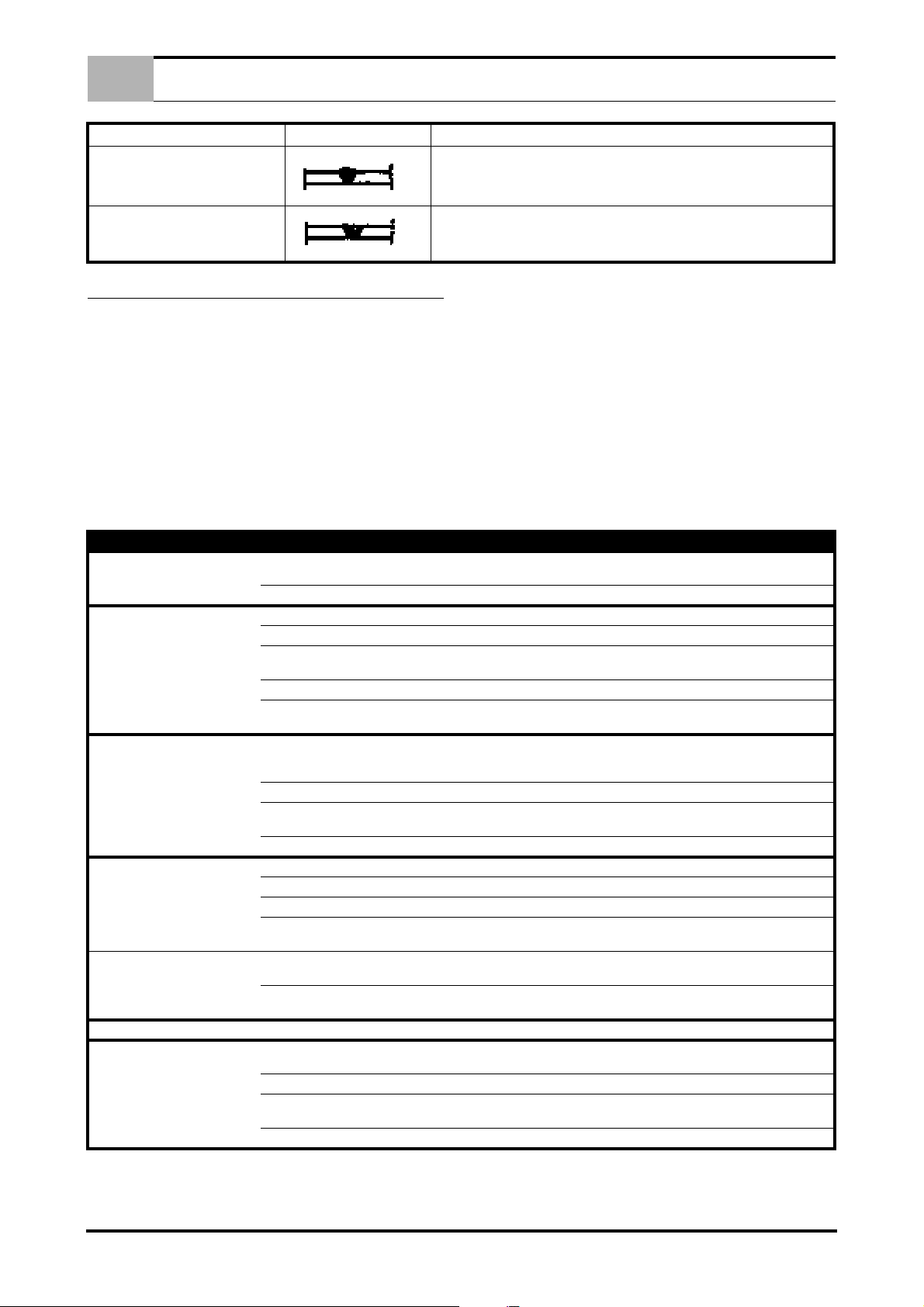
IT
DIFETTO ASPETTO CAUSA E RIMEDIO
MANUTENZIONI GENERALI
MANCANZA DI FUSIONE
CANALETTE
8.0 MANUTENZIONI GENERALI
- Distanza troppo corta.
- È necessario sgrossare oppure molare la saldatura e rifarla.
- Velocità di saldatura troppo elevata.
(Questo difetto facile da individuare visivamente, deve essere corretto subito dal
saldatore)
8.1 LE MANUTENZIONI GENERALI
1. UGELLO GUIDA GAS: spruzzare periodicamente dello
TOGLIERE TENSIONE AL GENERATORE PRIMA DI EFFETTUARE QUALSIASI MANUTENZIONE.
Procedere periodicamente (ogni 5/6 mesi) alla rimozione della
polvere che si accumula all'interno della saldatrice, usando un
getto di aria compressa secca (dopo aver tolto le fiancate).
SI RACCOMANDO QUINDI DI EVITARE PIEGAMENTI CHE
POSSONO PROVOCARE STROZZATURE ALLA TORCIA E DI
SPOSTARE IL GENERATORE TRAMITE LA TORCIA STESSA.
CONTROLLARE PERIODICAMENTE LO STATO DELLA TORCIA, ESSENDO LA PARTE PIÙ SOTTOPOSTA AD USURE.
spray per saldatura e pulire la parte interna dalle incrostazioni.
2. BECCUCCIO PASSAFILO: controllare che il foro di passaggio del filo non sia troppo allargato causa usura. In questo
caso sostituire il beccuccio.
8.2 CONNESSIONE DELLA TORCIA
Prima di collegare la torcia assicurarsi che la guaina (18) sia appropriata al diametro del filo che verrà utilizzato:
- colore BLU Ø 1.5 per fili di Ø 0,6 - 0,8 mm.
- colore ROSSO Ø 2.0 per fili di Ø 1 - 1,2 mm.
(Riferimenti colore guaine per fili in acciaio).
TYPE OF BREAKDOWN POSSIBLE CAUSES CHECKS AND REMEDIES
No functions operate.
Irregular wire feed. Insufficient spring pressure. Try tightening regulating knob.
Irregular wire feed.
Reduced welding power. Earth cable not connected.
Porous or spongy welds. No gas. Check presence of gas and gas supply pressure.
Porous or spongy welds. Faulty pressure regulator.
Gas supply does not switch off. Worn or dirty solenoid valve. Dismantle solenoid; clean hole and obturator.
Presslng torch trigger produces no
result.
Faulty power cord (one or more phases disconnected).
Blown fuse. Renew.
Wire-guide sheath blocked. Renew.
Wrong race - unsuitable for wire, or excessively
worn.
Braking on coil excessive. Loosen brake using adjusting screw.
Oxidized, poorly wound, poor quality wire, with
tangled or overlapping coils, etc.
Detached or loose connection on switches. Check, tighten or renew, as necessary.
Faulty contactor.
Faulty rectifier. Visually check for signs of burn-out; if present, renew rectifler.
Draughts in welding area. Use a suitable screen. Increase gas delivery pressure if necessary.
Ciogged holes in diffuser. Clear clogged holes using compressed air.
Gas leakage due to rupture in supply hoses.
Solenoid valve blocked.
Poor quality gas or wire.
Faulty torch trigger, disconnected or broken
control cables.
Blown fuse. Renew using a fuse of the same rating.
Faulty power switch.
Faulty electronic circuit. Renew circuit.
Check and remedy.
Turn roller over or change it.
Remedy by removing defective coils. If problem persists, change the
wire reel.
Check that the power cord is in good condition and make sure that the
ground clamps are flrmly fixed to the works piece, which must be free
of rust, grease and paint.
Check the state of the contacts and the mechanical efficiency of the
contactor.
Check and renew faulty component.
Check solenoid operation an electrical connection.
Check operation by removing the hose connecting the pressure regulator to the power source.
Gas must be extra-dry; change the cylinder or use a different type
wire.
Remove the torch connection plug and short-circuit the poles; if the
machine operates properly, check the cables and the torch trigger.
Clean with compressed air. Ensure that wires are tightly secured; renew switch if necessary.
5 IT

INHALTSVERZEICHNIS
1.0 BESCHREIBUNG UND TECHNISCHE DATEN . . . . . . . . . . . . . . . . . . . . . . . . . . . . . . . . . . . . . . . . . . . . . . 2
1.1 BESCHREIBUNG . . . . . . . . . . . . . . . . . . . . . . . . . . . . . . . . . . . . . . . . . . . . . . . . . . . . . . . . . . . . . . . . 2
1.2 TECHNISCHE MERKMALE . . . . . . . . . . . . . . . . . . . . . . . . . . . . . . . . . . . . . . . . . . . . . . . . . . . . . . . . 2
2.0 VERBINDUNG MIT DEM GENERATOR . . . . . . . . . . . . . . . . . . . . . . . . . . . . . . . . . . . . . . . . . . . . . . . . . . . . 2
3.0 INSTALLATION DER DRAHTSPULE . . . . . . . . . . . . . . . . . . . . . . . . . . . . . . . . . . . . . . . . . . . . . . . . . . . . . . 2
3.1 INSTALLATION DER DRAHTSPULE . . . . . . . . . . . . . . . . . . . . . . . . . . . . . . . . . . . . . . . . . . . . . . . . . 2
3.2 INBETRIEBNAHME . . . . . . . . . . . . . . . . . . . . . . . . . . . . . . . . . . . . . . . . . . . . . . . . . . . . . . . . . . . . . . . 2
4.0 BESCHREIBUNG DER BEDIENUNGEN DES SCHLEPPAGGREGATS . . . . . . . . . . . . . . . . . . . . . . . . . . 3
4.1 VORDERE SCHALTTAFEL . . . . . . . . . . . . . . . . . . . . . . . . . . . . . . . . . . . . . . . . . . . . . . . . . . . . . . . . 3
5.0 RUNDBEGRIFFE DES MIG-MAG SCHWEIßVERFAHRENS . . . . . . . . . . . . . . . . . . . . . . . . . . . . . . . . . . . . 3
6.0 ANSCHLUß UND VORBEREITUNG ZUM SCHWEIßEN . . . . . . . . . . . . . . . . . . . . . . . . . . . . . . . . . . . . . . . 3
6.1 SCHWEIßEN . . . . . . . . . . . . . . . . . . . . . . . . . . . . . . . . . . . . . . . . . . . . . . . . . . . . . . . . . . . . . . . . . . . . 4
6.2 SCHWEIßEN VON KOHLENSTOFFSTAHL . . . . . . . . . . . . . . . . . . . . . . . . . . . . . . . . . . . . . . . . . . . . 4
DE
6.3 SCHWEIßEN VON ROSTFREIEM EDELSTAHL . . . . . . . . . . . . . . . . . . . . . . . . . . . . . . . . . . . . . . . . 4
6.4 SCHWEIßEN VON ALUMINIUM . . . . . . . . . . . . . . . . . . . . . . . . . . . . . . . . . . . . . . . . . . . . . . . . . . . . . 4
6.5 PUNKTEN . . . . . . . . . . . . . . . . . . . . . . . . . . . . . . . . . . . . . . . . . . . . . . . . . . . . . . . . . . . . . . . . . . . . . . 4
7.0 FEHLER BEIM MIG-SCHWEIßEN . . . . . . . . . . . . . . . . . . . . . . . . . . . . . . . . . . . . . . . . . . . . . . . . . . . . . . . . 4
7.1 LISTE UND BESCHREIBUNG DER FEHLER . . . . . . . . . . . . . . . . . . . . . . . . . . . . . . . . . . . . . . . . . . 4
8.0 ALLGEMEINE WARTUNGSARBEITEN . . . . . . . . . . . . . . . . . . . . . . . . . . . . . . . . . . . . . . . . . . . . . . . . . . . . 5
8.1 ALLGEMEINE WARTUNGSARBEITEN . . . . . . . . . . . . . . . . . . . . . . . . . . . . . . . . . . . . . . . . . . . . . . . 5
8.2 BRENNERANSCHLUß . . . . . . . . . . . . . . . . . . . . . . . . . . . . . . . . . . . . . . . . . . . . . . . . . . . . . . . . . . . . 5
ERSATZATEILLISTE . . . . . . . . . . . . . . . . . . . . . . . . . . . . . . . . . . . . . . . . . . . . . . . . . . . . . . . . . . . . . . . . . . . . .I - XII
STROMLAUFPLAN . . . . . . . . . . . . . . . . . . . . . . . . . . . . . . . . . . . . . . . . . . . . . . . . . . . . . . . . . . . . . . . . . . . XIII - XIV
1 DE
DE
SCHWEIßDRÄHTE KÖNNEN STICHWUNDEN VERURSA-
CHEN.
Beim Einfädeln des Drahtes den Brenner niemals gegen Körperteile, andere Personen, oder Metall richten.
BESCHREIBUNG UND TECHNISCHE DATEN
1.0 BESCHREIBUNG UND TECHNISCHE DATEN
1.1 BESCHREIBUNG
Der Schweißarbeit Draht und bildet, mit einem Generator, eine
Anlage, die sich für das Gleichstyrom-Lichtbogenschweissen anpasst. Zusammen mit den Generatoren ist er imstande, viele Arbeitsanforderungen zu erfüllen.
1.2 TECHNISCHE MERKMALE
Model 345A
Auswahl Volldrähte* Ø 0,6 ÷ 1,2 mm
Auswahl
Seelendrähte*
Spulengrößen Ø 300 mm
Gas** Ar oder CO2 oder MIX (max 4 bar)
Kühlflüssigkeit -
Model 450A 450A H
Auswahl Volldrähte* Ø 0,6 ÷ 1,6 mm Ø 0,6 ÷ 1,6 mm
Auswahl
Seelendrähte*
Spulengrößen Ø 300 mm Ø 300 mm
Gas**
Kühlflüssigkeit -
Ø 0,8 ÷ 2,4 mm Ø 0,8 ÷ 2,4 mm
Ar oder CO2 oder MIX
(max 4 bar)
* Zur Verwendung des ganzen Sortiments der möglichen Drähte
muss die Ausstattung der Drahtvorschubrollen um jene mit den
passenden Rillen erweitert werden (z.B. gerändelte Rillen für
Seelendrähte)
** Das zu verwendende Schutzgas hängt von dem Metall ab, das
geschweißt werden soll, siehe einige Beispiele der folgenden Tabelle:
Ø 0,8 ÷ 1,2 mm
Ar oder CO2 oder MIX
(max 4 bar)
Wasser mit 30% Frost-
schutzmittel Glykol
max. 5 bar
Rollen ist die Einstellmutter nicht sichtbar; in diesem Fall die
Keilnase nach außen ziehen).
3. Die Brücke der oberen Drahtvorschubgruppe öffnen
4. Kontrollieren, dass die Rollen für den Drahtdurchmesser, der
verwendet werden soll, geeignet sind; gegebenenfalls die
Rollen auswechseln.
5. Ein Drahtende gerade richten und abschneiden.
6. Den Draht über die beiden unteren Rollen führen und in das
Rohr des Brenneranschlusses so weit einschieben, bis er ca.
10 cm aus demselben hervorragt.
7. Die Brücke der oberen Zugvorrichtung wieder schließen und
sich vergewissern, dass der Draht-genau in der Kehle liegt.
8. Den Schweißbrenner anschließen und den aus dem Anschluss ragenden Draht in den Schutzmantel schieben; dabei die Steckerstifte in die betreffenden Sitze stecken und
den Verbindungsring fest anziehen.
3.2 INBETRIEBNAHME
1. Die Maschine einschalten.
2. Den Leistungsumschalter auf eine mittlere Position stellen.
3. Die Düse und das Mundstück der Drahtdurchführung von
dem Brenner entfernen; die Brennertaste drücken (Bez. 8 Bild 1 Seite 3.) und den Draht so weit abrollen lassen, bis er
auf der Vorderseite des Schweißbrenners austritt. Während
des Drahtablaufs im Schweißbrenner mithilfe des Handrads
den Druck einstellen, den die Drahtandrückrolle auf die Zugrolle ausüben soll; es ist wichtig, dass der Vorschub des
Schweißdrahts gleichmäßig ohne Schlupf und ohne Verformungen erfolgt. Den Schweißbrenner mit einem geeigneten
Mundstück der Drahtdurchführung versehen, die dem eingesetzten Draht entspricht.
4. Das Mundstück der Drahtdurchführung wieder anschrauben
und sich vorher vergewissern, dass dasselbe für den verwendeten Drahtdurchmesser geeignet ist.
Zu schweißendes Material Verwendbares Schutzgas
Stahl CO2 oder MIX (Ar + CO2)
Edelstahl MIX (Ar + O2)
Aluminium Ar
2.0 VERBINDUNG MIT DEM GENERATOR
1. Erstens soll man sicher sein, dass der Generator ausgeschaltet ist.
2. Den Kraftstecker der Nabelschnur mit dem passenden Stecker, der sich auf der hinteren Platte des Geräts befindet,
verbinden. (Man soll ihn ganz hineinstecken im Uhrzeigensinn drehen, bis man zur völligen Sperrung angelangt ist).
3. Den mehrpoligen Stecker mit der betreffenden Steckdose
verbinden und ihn mit der vorbereiteten Verschlussvorrichtung sperren.
4. Das aus der Nabelschnur herauskommende Gasrohr mit
dem Gasflaschedruckminderer verbinden.
3.0 INSTALLATION DER DRAHTSPULE
3.1 INSTALLATION DER DRAHTSPULE
1. Die Drahtspule so in die Rolle einsetzen, dass beide zusammen drehen.
2. Die Spulenbremse mit der mittleren Schraubenmutter so einregulieren, dass die Spule ohne Reibung dreht (bei einigen
5. Die Gasdüse wieder einbauen.
6. Den Hahn der Gasflasche öffnen.
7. Die Erdungszange an dem Werkstück in einem Punkt anschließen, der frei von Rost, Lack, Fett oder Kunststoff ist.
ACHTUNG: FALLS BEI DER SCHWEIßARBEIT DIE AN DEM
OPTIONALEN HAKEN WIRD, MUSS SICHERGESTELLT
WERDEN, DASS DER RAHMEN DER DRAHTZUFÜHRUNG
VOM ERDUNGSKREIS ISOLIERT IST (ZUM BEISPIEL HUBSEILE AUS NYLON ODER SONSTIGEM ISOLIERMATERIAL
VERWENDEN). DIESE MAßNAHME IST UNBEDINGT NOTWENDIG, UM EIN SCHLIEßEN DES SCHWEIßSTROMS ÜBER
DIE HUBMITTEL UND DEN ERDUNGSKREIS DER ELEKTRISCHEN ANLAGE ZU VERMEIDEN.
DURCH MISSACHTUNG DIESER SICHERHEITSBESTIMMUNG KÖNNEN ERNSTHAFTE SCHÄDEN AN DER ELEKTRISCHEN ANLAGE VERURSACHT, UND DAS HUBSYSTEM
DES WAGENS BEEINTRÄCHTIGT WERDEN.
2 DE
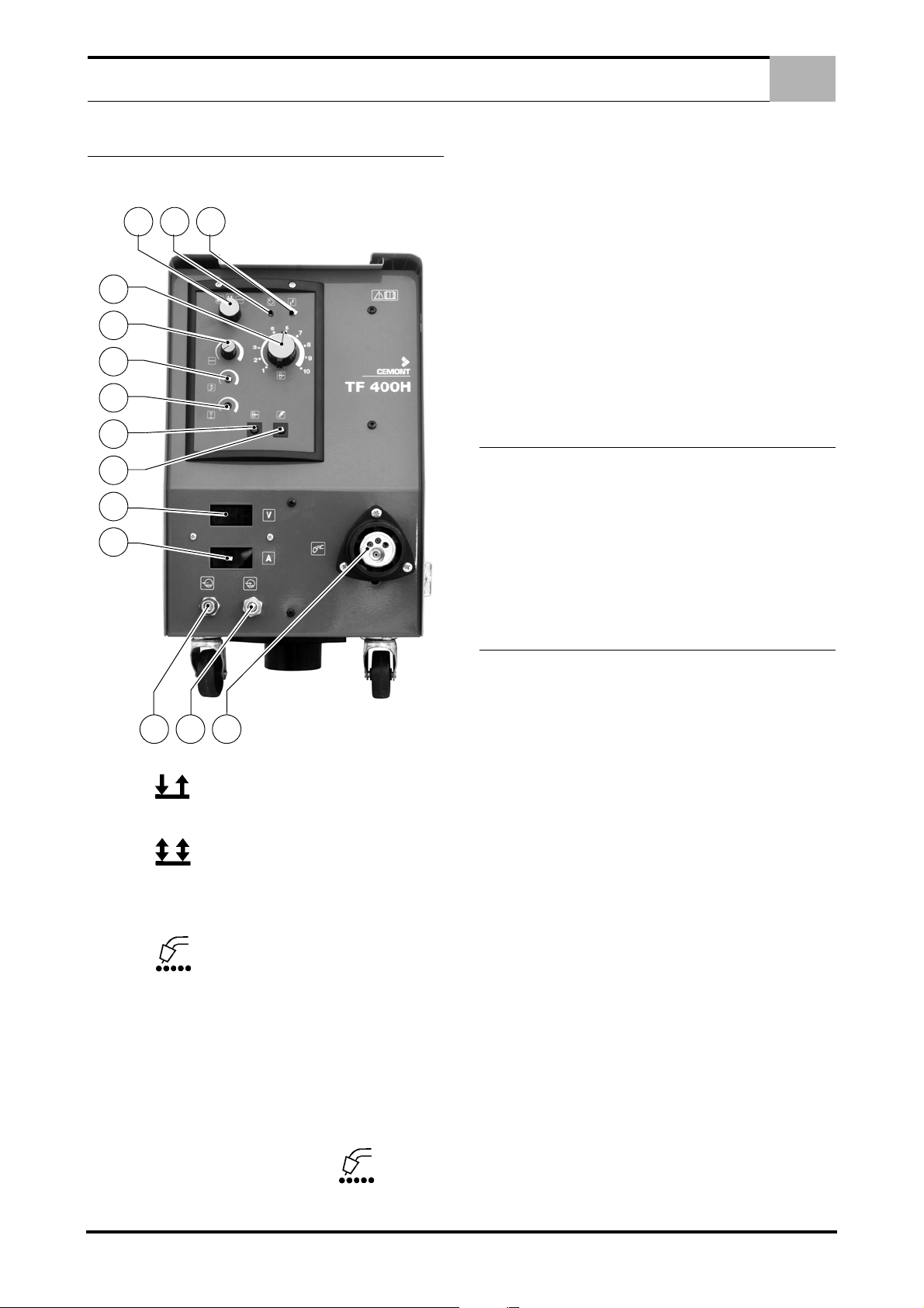
BESCHREIBUNG DER BEDIENUNGEN DES SCHLEPPAGGREGATS
3
2
1
4
5
6
7
8
9
14
15
10
17
16
DE
4.0 BESCHREIBUNG DER BEDIENUNGEN DES
SCHLEPPAGGREGATS
4.1 VORDERE SCHALTTAFEL
Bild 1.
6 - Potentiometer zur Einstellung der Beschleunigungsdauer
des Drahtvorschubmotors.
7 - Potentiometer zur Einstellung der Zeit, für die die Schweißleistung nach dem Haltimpuls aufrecht erhalten bleibt. Falls diese
Zeit bei Beendigung der Schweißung zu kurz ist, bleibt der Draht
in der Schmelze kleben oder ragt zu weit aus dem Kontaktröhrchen des Brenners hervor; ist die Zeit dagegen zu lang eingestellt,
kann der Draht auf dem Kontaktröhrchen des Schweißbrenners
verkleben und denselben beschädigen.
8 - Drahtvorschubschalter ( ohne “Strom” )
9 - Gasausgangstestschalter
10 - Euro - Schweißbrenneranschluss
14 - Spannungsmesser
15 - Strommesser
16 - Anschluss Kühlwasserzuleitung (blau)
17 - Anschluss Kühlwasserrücklauf (rot)
5.0 RUNDBEGRIFFE DES MIG-MAG SCHWEIßVERFAHRENS
PRINZIP DES MIG-SCHWEIßVERFAHRENS
Das MIG-Schweißverfahren verschmelzt, wie beim AutogenSchweißen, zwei gleichartige Werkstücke (Stahl, Edelstahl, Aluminium) und garantiert nach der Verbindung die gleichen mechanischen und physischen Eigenschaften. Die notwendige Hitze für
den Schweißvorgang wird durch einen Lichtbogen erzeugt, d.h.
einen Kurzschluß zwischen dem Draht und dem Werkzeug. Um
den Lichtbogen und das Schweißbad vor einer Oxydation durch
die Luft zu schützen, benötigt man das Schutzgas.
1 - Wählschalter des Schweißsystems:
In Stellung die Brennertaste drücken, um den Schweißvorgang zu starten, die Taste freigeben, um das Schweißen zu
beenden.
In Stellung der Tastendruck öffnet den Gashahn, nach
Tastenfreigabe werden der Drahtvorschub und der Strom eingeschaltet; ein weiterer Tastendruck schaltet den Strom und den
Drahtvorschub ab; nach Loslassen der Taste wird der Gashahn
geschlossen.
In Stellung die Schweißmaschine arbeitet mit Zeitschaltung; der Druck auf die Brennertaste schaltet den Schweißprozess ein, der automatisch nach der mit dem Potentiometer des
Schweißbegrenzers vorgegebenen Zeit beendet wird (Bez. 5 Bild 1 Seite 3.).
2 - Betriebsanzeige
3 - Warnleuchte Maschinenüberhitzung
4 - Potentiometer zur Einstellung der Draht - Vorschubge-
schwindigkeit
5 - Potentiometer zur Einstellung der Punktschweißdauer, von
0,3 bis 10 Sekunden (nur möglich, wenn der Wählschalter auf
Stellung (Bez. 1 - Bild 1 Seite 3.) gedreht ist)
6.0 ANSCHLUß UND VORBEREITUNG ZUM
SCHWEIßEN
VERBINDEN SIE SORGFÄLTIG DAS ZUBEHÖR MIT DEM
GERÄT UM GEFÄHRLICHE LEISTUNGS- ODER GASVERLUSTE ZU VERMEIDEN.
Halten Sie sich rigoros an die im Kap. 1.0 angegebenen Sicherheitsvorschriften.
ACHTUNG DREHEN SIE NICHT AN DEN SCHALTERN
WÄHREND DES SCHWEIßEN, DAS GERÄT KANN DAMIT BESCHÄDIGT WERDEN.
DEN GASAUSTRITT KONTROLLIEREN UND DEN
GASSTROM MIT DEM HAHN DES DRUCKMINDERVENTILS
REGULIEREN.
ACHTUNG! BEIM SCHWEIßEN IM FREIEN ODER BEI WINDBÖEN MUß DARAUF GEACHTET WERDEN, DAß DAS
SCHUTZGAS OM WIND NICHT ABGELEITET WIRD UND
SOMIT DEM LICHTBOGEN KEINEN SCHUTZ MEHR BIETEN
WÜRDE.
3 DE
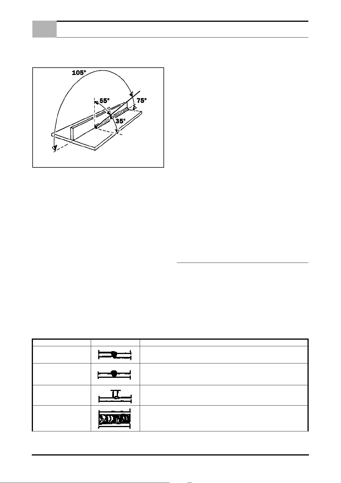
DE
6.1 SCHWEIßEN
1. Öffnen Sie die Gasflasche und regeln den Gasfluß je nach
Schweißposition. Klemmen Sie die Masse an das Werkstück
in einem Punkt ohne Lack, Plastik oder Rost.
Für eine optimale Schweißnaht richten Sie Brenner und
Draht wie in Abbildung aus.
2. Wählen Sie den Schweißstrom mit dem Stufenschalter (Bez.
11 - Bild 1 Seite 3.) und bedenken Sie, daß je dicker das
Werkstück, je stärker der Schweißstrom. Die ersten Schaltstufen sind besonders für dünne Werkstücke geeignet. Beachten Sie auch, daß jeder Schaltstufe eine bestimmte
Drahtvorschubgeschwindigkeit entspricht, die durch den Potentiometer eingestellt werden kann (Bez. 4 - Bild 1 Seite 3.).
6.2 SCHWEIßEN VON KOHLENSTOFFSTAHL
Zum MIG-Schweißen ist für dieses Material folgendes notwendig:
1. Verwenden Sie ein binäres Schutzgas, meistens AR/CO2 mit
einem Anteil von 75% bis 80% an Argon und 25% bis 20%
an CO2, oder ein ternäres Schutzgas wie z.B. AR/CO2/
O2.Diese Gasmischungen erzeugen Hitze beim Schweißen
und ergeben eine kompakte Schweißnaht, andererseits resultiert der Einbrand nicht besonders tief. Indem Sie Kohlensäure als Schutzgas verwenden (MAG) erhalten Sie eine
enge Schweißnaht mit tiefem Einbrand, jedoch beeinflußt die
Ionisation des Gases die Stabilität des Lichtbogens.
2. Benutzen Sie einen Schweißdraht aus dem gleichen Material
des Werkstückes. Es ost vorteilhaft wenn Sie immer einen
Schweißdraht aus guter Qualität benuten, vermeiden Sie
verrostete oder oxydierte Drähte welche das Schweißergebnis stark beeinflussen. Für den einzustellenden Strombereich der Drähte gilt folgende Faustregel:
- Drahtdurchmesser x 100 = min. Ampere
- Drahtdurchmesser x 200 = max. Ampere
Beispiel: Drahtdurchmesser 1,2 mm = minimale Amperezahl
120 maximal 240/Amp.
Dies gilt für binäre Gasmischungen AR/CO2 und kurzem
Lichtbogen (SHORT).
FEHLER FORM URSACHE UND ABHILFE
HÖHENUNTERSCHIED
ZU DICKE NAHT
FEHLER BEIM MIG-SCHWEIßEN
3. Vermeiden Sie auf verrosteten oder verölten Werkstücken zu
4. Benutzen Sie ein der Amperezahl entsprechendes
5. Überprüfen Sie regelmäßig das Massekabel und die Mas-
6.3 SCHWEIßEN VON ROSTFREIEM EDELSTAHL
Das Verschweißen von rostfreiem Stahl der Qualität 300, muß mit
einem hohen Prozentsatz an Argon und einem kleinen Anteil an
O2 im Schutzgas durchgeführt werden, um den Lichtbogen stabil
zu halten. Die meist gebrauchte Mischung ist AR/O2 98/2.
Auftragsmaterial muß eine höhere Qualität vorweisen als das Basismaterial und die zu verschweißenden Stellen müssen absolut sauber sein.
6.4 SCHWEIßEN VON ALUMINIUM
Für das MIG-Schweißen von Aluminium ist folgendes notwendig:
1. Ein 100 prozentiges Argon als Schutzgas.
2. Ein dem Basismaterial entsprechender Schweißdraht. Für
3. Einen für Aluminium ausgestatteten Brenner.
6.5 PUNKTEN
Dieses spezielle Schweißerfahren erlaubt, zwei überlappende Bleche
zusammenzuheften. Hierzu braucht man eine spezielle Gasdüse.
Montieren Sie die Gasdüse zum Punkten, drücken Sie die Düse
auf das Werkstück. Drücken Sie die Brennertaste. Nach einer gewissen Zeit schaltet das Schweißgerät automatisch ab. Diese
Punktschweißzeit wird durch den Timer (Bez. 5 - Bild 1 Seite 3.)
bestimmt, und muß in Bezug auf die Stärke des Werstückes eingestellt werden.
7.0 FEHLER BEIM MIG-SCHWEIßEN
7.1 LISTE UND BESCHREIBUNG DER FEHLER
Die im MIG-Schweißerfahren erzeugten Schweißnähte können
verschiedene Fehler haben, deshalb ist es wichtig, diese zu identifizieren. Diese Fehler unterscheiden sich nicht in ihrer Art und
Form von denen , die im Schweißverfahren mit ummantelten Stabelektroden gemacht werden. Der Unterschied bei den zwei Verfahren ist, daß die Häufigkeit der Fehler nicht die gleiche ist,
poröse Schweißnähte sind z. B. häufiger im MIG-Schweißverfahren, während die Verschmutzung durch Schlacke häufiger bei der
Anwendung von ummantelten Stabelektroden vorkommt.
Folgende Tabelle gibt eine Übersicht der Fehler an.
- Schlechte Vorbereitung
- Die Seiten aneinanderlegen und beim Schweißen festhalten
- Leerlaufspannung zu niedrig
- Schweißgeschwindigkeit zu langsam
- Falsche Neigung des Brenners
- Drahtdurchmesser zu dick
schweißen
Schlauchpaket
seklemme. Schnitte und Verbrennungen können die Wirkung
stark beeinträchtigen.
- Benutzen Sie kein CO2 oder Mischgas AR/CO2
- Berühren Sie nicht den Schweißdraht mit den Händen. Das
ALUMAN und ANTICORODAL benutzt man einen Siliziumanteil von 3 bis 5% Für PERALUMAN und ERGAL einen
Magnesiumanteil von 5 %.
SCHWACHER AUFTRAG
OXYDIERTE SCHWEIßNAHT
- Zu hohe Schweißgeschwindigkeit
- Zu niedrige Spannung für die angewandte Schweißgeschwindigkeit
- Bei langem Lichtbogen in der Rille schweißen
- Spannung regeln
- Abgeknickter oder zu langer Schweißdraht außerhalb der Stromdüse
- Falsche Drahtgeschwindigkeit
4 DE
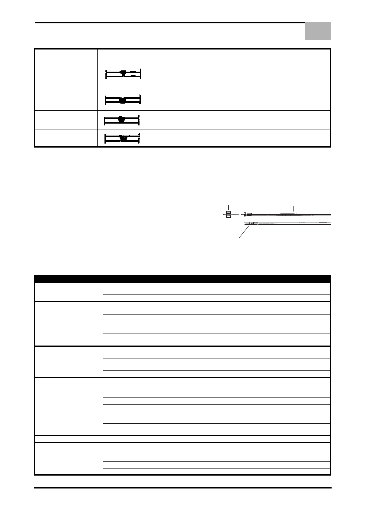
ALLGEMEINE WARTUNGSARBEITEN
19
21
18
20
22
FEHLER FORM URSACHE UND ABHILFE
- Zu geringer oder unregelmässiger Abstand
SCHWACHER EINBRAND
- Falsche Brennerneigung
- Stromdüse verschlissen
- Zu niedrige Vorschubgeschwindigkeit gegenüber der Spannung oder der Schweißgeschwindigkeit
DE
ZU TIEFEN EINBRAND
BINDEFEHLER
RILLEN
8.0 ALLGEMEINE WARTUNGSARBEITEN
UNTERBRECHEN SIE DIE NETZSPANNUNG VOR JEDER
WARTUNGSARBEIT.
Entfernen Sie regelmässig, alle 5-6 Monate den Staub im Geräteinneren mittels Druckluft.
- Zu hohe Drahtgeschwindigkeit
- falsche Brennerneigung
- Zu hoher Abstand
- Abstand zu gering
- Man Muß die Schweißnaht ausschruppen oder ausschleifen und erneut ausführen.
- Zu hohe Schweißgeschwindigkeit
(Dieser Fehler ist einfach zu erkennen und muß vom
Schweißer sofort korrigiert werden.
2. STROMDÜSE Kontrollieren Sie daß sich die Bohrung nicht
infolge von Verschleiß geweitet hat, in diesem Fall ersetzen
Sie die Gasdüse.
8.2 BRENNERANSCHLUß
Bevor Sie den Brenner anschließen, versichern Sie sich, daß die
Drahtseele dem Drahtdurchmesser entspricht:
VERMEIDEN SIE DAS SCHLAUCHPAKET ZU KNICKEN UND
DAS GERÄT BEIM TRANSPORT AM BRENNER FESTZUHALTEN.
KONTROLLIEREN SIE REGELMÄSSIG DEN ZUSTAND DES
BRENNERS, DA DIESER DEM GRÖSSTEN VERSCHLEIß UNTERLIEGT.
8.1 ALLGEMEINE WARTUNGSARBEITEN
1. GASDÜSE Besprühen Sie sie regelmässig mit einem Spray
für Schweißgeräte und säubern Sie das Innere.
- Farbe BLAU Durchm. 1,5 für Drähte von 0,6 bis 0,8 mm
- Farbe ROT Durchm. 2,0 für Drähte von 1 bis 1,2 mm
(Die Farben der Drahtseelen oder Drahtführungsspiralen
beziehen sich auf Stahldrähte).
FEHLERART URSACHEN KONTROLLE UND ABHILFE
Keine Funktionen mehr.
Unregelmäßiger Drahtvorschub. Mangelhafter Gegendruck der Vorschubeinheit. Anziehen der Druckschraube den Druck zu verbessern.
Reduzierte Schweißleistung. Massekabel nicht richtig angeschlossen.
Poröse Schweißnaht. Fehlen von Gas. Kontrollieren Sie den Gasfluß und dessen Druck.
Permanenter Gasaustritt. Magnetventil verschlissen oder verschmutzt. Magnetventil ausbauen und Öffnung und Bohung säubern.
Keine Funktion der Brennertaste. Schalter defekt, Steuerleitung lokker.
Netzkabel unterbrochen (Eine oder mehr Phasen).
Sicherung durchgebrannt. Austauschen.
Drahtführungsseele/spirale verstopft. Austauschen.
Falsche oder verschlissene Nut der Förderrolle.
Zu starke Drahtspulenbremse. Bremse lockern.
Draht verrostet, schlechte Qualität, schlecht
gespult, überlappende Wicklungen.
Lose Kabel Wackelkontakt defekter Schutz.
Defekter Gleichrichter. Kontrollieren sie diesen auf Brandstellen, evtl. ersetzen.
Luftzug im Arbeitsbereich. Verwenden Sie einen Windschutz, erhöhen Sie evtl. den Gasdruck.
Gasdiffusor verstopft. Mit Druckluft freimachen.
Gasaustritt, defekter Gasschlauch. Kontrollieren und ersetzen Sie die defekten Teile.
Magnetventil blockiert. Zustand und elektrischen Anschluß prüfen.
Druckminderer defekt.
Schlechte Gas- oder Drahtqualität.
Sicherung durchgebrannt. Sicherung ersetzen.
Poti defekt. Mit Luft säubern, Kabelanschlüsse überprüfen.
Elektronik defekt. Ersetzen.
Überprüfen und abhelfen.
Wenn verschlissen austauschen.
Wenn falsch, richtige einsetzen.
Kabel untersuchen. Kontrollieren Sie, daß das mit der Masseklemme
verbundene Werkstück frei von Rost, Fett und Lack ist.
Kontrollieren, festziehen, evtl. ersetzen.
Überprüfen Sie den Zustand und die Funktionsfähigkeit des Schützes.
Überprüfen Sie die Funktion indem Sie den Gasschlauch des Gertes
abziehen.
Benutzen Sie supertrockenes Gas, ersetzen Sie Gas oder Draht mit
einer anderen Qualität.
Entfernen Sie den Brennerstecker und schließen Sie die beiden Pole
kurz, wenn das Gerät funktioniert, Kabel und Mikrotaste überprüfen.
5 DE

PT
1.0 DESCRIÇÃO E CARACTERÍSTICAS TÉCNICAS . . . . . . . . . . . . . . . . . . . . . . . . . . . . . . . . . . . . . . . . . . . . 2
1.1 DESCRIÇÃO . . . . . . . . . . . . . . . . . . . . . . . . . . . . . . . . . . . . . . . . . . . . . . . . . . . . . . . . . . . . . . . . . . . . 2
1.2 CARACTERÍSTICAS TÉCNICAS . . . . . . . . . . . . . . . . . . . . . . . . . . . . . . . . . . . . . . . . . . . . . . . . . . . . 2
2.0 CONEXÃO À GERADOR . . . . . . . . . . . . . . . . . . . . . . . . . . . . . . . . . . . . . . . . . . . . . . . . . . . . . . . . . . . . . . . 2
3.0 INSTALAÇÃO DA BOBINA DO FIO . . . . . . . . . . . . . . . . . . . . . . . . . . . . . . . . . . . . . . . . . . . . . . . . . . . . . . . 2
3.1 INSTALAÇÃO DA BOBINA DO FIO . . . . . . . . . . . . . . . . . . . . . . . . . . . . . . . . . . . . . . . . . . . . . . . . . . 2
3.2 COMO PÔR A FUNCIONAR . . . . . . . . . . . . . . . . . . . . . . . . . . . . . . . . . . . . . . . . . . . . . . . . . . . . . . . . 2
4.0 DESCRIÇÃO DOS COMANDOS DO PAINEL FRONTAL . . . . . . . . . . . . . . . . . . . . . . . . . . . . . . . . . . . . . . 3
4.1 PAINEL ANTERIOR . . . . . . . . . . . . . . . . . . . . . . . . . . . . . . . . . . . . . . . . . . . . . . . . . . . . . . . . . . . . . . 3
5.0 NOÇÕES BÁSICAS PARA SOLDADURA MIG . . . . . . . . . . . . . . . . . . . . . . . . . . . . . . . . . . . . . . . . . . . . . . 3
6.0 LIGAÇÃO E PREPARAÇÃO DO EQUIPAMENTO PARA SOLDADURA . . . . . . . . . . . . . . . . . . . . . . . . . . 3
6.1 SOLDADURA . . . . . . . . . . . . . . . . . . . . . . . . . . . . . . . . . . . . . . . . . . . . . . . . . . . . . . . . . . . . . . . . . . . 3
6.2 SOLDADURA DE AÇOS AO CARBONO . . . . . . . . . . . . . . . . . . . . . . . . . . . . . . . . . . . . . . . . . . . . . . 4
ÍNDICE
6.3 SOLDADURA DE AÇOS INOXIDÁVEIS . . . . . . . . . . . . . . . . . . . . . . . . . . . . . . . . . . . . . . . . . . . . . . . 4
6.4 SOLDADURA DE ALUMÍNIO . . . . . . . . . . . . . . . . . . . . . . . . . . . . . . . . . . . . . . . . . . . . . . . . . . . . . . . 4
6.5 SOLDADURA POR PONTOS . . . . . . . . . . . . . . . . . . . . . . . . . . . . . . . . . . . . . . . . . . . . . . . . . . . . . . . 4
7.0 DEFEITOS DE SOLDADURA MIG . . . . . . . . . . . . . . . . . . . . . . . . . . . . . . . . . . . . . . . . . . . . . . . . . . . . . . . . 4
8.0 MANUTENÇÃO GERAL . . . . . . . . . . . . . . . . . . . . . . . . . . . . . . . . . . . . . . . . . . . . . . . . . . . . . . . . . . . . . . . . 5
8.1 OPERAÇÕES DE MANUTENÇÃO GERAL . . . . . . . . . . . . . . . . . . . . . . . . . . . . . . . . . . . . . . . . . . . . 5
8.2 LIGAÇÃO DO MAÇARICO . . . . . . . . . . . . . . . . . . . . . . . . . . . . . . . . . . . . . . . . . . . . . . . . . . . . . . . . . 5
PEÇAS SOBRESSELENTES . . . . . . . . . . . . . . . . . . . . . . . . . . . . . . . . . . . . . . . . . . . . . . . . . . . . . . . . . . . . . .I - XII
ESQUEMAS ELÉCTRICOS . . . . . . . . . . . . . . . . . . . . . . . . . . . . . . . . . . . . . . . . . . . . . . . . . . . . . . . . . . . . XIII - XIV
1 PT
 Loading...