

CEMONT SMARTY TX 150 Safety Instruction For Use And Maintenance
SMARTY TX 150
EN Safety instruction for use and maintenance - Do not destroy this manual
FR Instruction de securite d’emploi et d’entretien - Conserver ce livret d’instructions
ES Instrucciones de seguridad, empleo y mantenimiento - Conservar el presente manual
IT Istruzioni per la sicurezza nell’uso e per la manutenzione - Conservare il presente libretto
DE Betriebs-Wartungs und Sicherheitsanleitung - Das vorliegende Handbuch gut aufbewahren
PT Instrucões de segurança de utilização e de manutenção - Conserve este manual
SV Instruktioner för säkerhet, använding och underåll - Spar denna handledning
NL Veiligheidsinstructies voor gebruik en onderhoud - Bewaar deze handleiding
RO Instructiuni privind siguranta in exploatare si intretinerea - Pastrati acest manual
SK Bezpečnostné pokyny pri používaní a pri údržbe - Odložte si tento návod na použitie
CS Bezpečnostní pokyny pro používání a údržbu - Návod na používání si uchovejte
HU Használati és karbantartási biztonsági utasítások - Kerjük őrizze meg ezt a hasznsnalati utasítást
PL Instrukcje bezpieczeństwa podczas obsługi i konserwacji - Zachować niniejszą instrukcję na przyszłość
EL ΟΔΗΓΙΕΣ ΑΣΦΑΛΕΙΑΣ ΚΑΤΑ ΤΗ ΧΡΗΣΗ ΚΑΙ ΤΗ ΣΥΝΤΗΡΗΣΗ – ΦΥΛΑΞΤΕ ΤΟ ΠΑΡΟΝ ΕΓΧΕΙΡΙΔΙΟ
RU РУКОВОДСТВО ПО БЕЗОПАСНОЙ ЭКСПЛУАТАЦИИ И ТЕХНИЧЕСКОМУ ОБСЛУЖИВАНИЮ
Cat. Nr.:
Rev.:
Date:
800035050
02
05. 02. 2008
www.airliquidewelding.com
Air Liquide Welding - 13, rue d’Epluches - BP 70024 Saint-Ouen L’Aumône

Welding Operations Services Slovakia, spol. s r.o.
Hlohovecká 6, 951 41 Nitra - Lužianky, SLOVAK REPUBLIC
MEMBER OF AIR LIQUIDE WELDING GROUP.

CONTENTS
1.0 TECHNICAL DESCRIPTION . . . . . . . . . . . . . . . . . . . . . . . . . . . . . . . . . . . . . . . . . . . . . . . . . . . . . . . . . . . . . 3
1.1 DESCRIPTION . . . . . . . . . . . . . . . . . . . . . . . . . . . . . . . . . . . . . . . . . . . . . . . . . . . . . . . . . . . . . . . . . . 3
1.2 TECHNICAL DATA . . . . . . . . . . . . . . . . . . . . . . . . . . . . . . . . . . . . . . . . . . . . . . . . . . . . . . . . . . . . . . . 3
1.3 ACCESSORIES . . . . . . . . . . . . . . . . . . . . . . . . . . . . . . . . . . . . . . . . . . . . . . . . . . . . . . . . . . . . . . . . . . 3
1.4 DUTY CYCLE AND OVERHEATING . . . . . . . . . . . . . . . . . . . . . . . . . . . . . . . . . . . . . . . . . . . . . . . . . 3
1.5 VOLT - AMPERE CURVES . . . . . . . . . . . . . . . . . . . . . . . . . . . . . . . . . . . . . . . . . . . . . . . . . . . . . . . . . 3
2.0 INSTALLATION . . . . . . . . . . . . . . . . . . . . . . . . . . . . . . . . . . . . . . . . . . . . . . . . . . . . . . . . . . . . . . . . . . . . . . . 3
2.1 CONNECTING THE POWER SOURCE TO THE MAINS ELECTRICITY SUPPLY . . . . . . . . . . . . . . 3
2.2 HANDLING AND TRANSPORTING THE POWER SOURCE . . . . . . . . . . . . . . . . . . . . . . . . . . . . . . . 3
2.3 CONNECTION AND PREPARATION OF EQUIPMENT FOR STICK WELDING . . . . . . . . . . . . . . . . 3
2.4 CONNECTION AND PREPARATION OF EQUIPMENT FOR GAS TUNGSTEN ARC WELDING (TIG) . . .3
2.5 MANUAL GTAW (TIG) WELDING . . . . . . . . . . . . . . . . . . . . . . . . . . . . . . . . . . . . . . . . . . . . . . . . . . . . 4
EN
2.6 AUTOMATIC GTAW (TIG) WELDING . . . . . . . . . . . . . . . . . . . . . . . . . . . . . . . . . . . . . . . . . . . . . . . . . 4
3.0 FUNCTIONS . . . . . . . . . . . . . . . . . . . . . . . . . . . . . . . . . . . . . . . . . . . . . . . . . . . . . . . . . . . . . . . . . . . . . . . . . 4
3.1 FRONT PANEL . . . . . . . . . . . . . . . . . . . . . . . . . . . . . . . . . . . . . . . . . . . . . . . . . . . . . . . . . . . . . . . . . . 4
3.2 REAR PANEL . . . . . . . . . . . . . . . . . . . . . . . . . . . . . . . . . . . . . . . . . . . . . . . . . . . . . . . . . . . . . . . . . . . 5
4.0 MAINTENANCE . . . . . . . . . . . . . . . . . . . . . . . . . . . . . . . . . . . . . . . . . . . . . . . . . . . . . . . . . . . . . . . . . . . . . . . 5
5.0 TYPES OF MALFUNCTIONING/ WELDING FAULTS – CAUSES – REMEDIES . . . . . . . . . . . . . . . . . . . . 5
SPARE PARTS LIST . . . . . . . . . . . . . . . . . . . . . . . . . . . . . . . . . . . . . . . . . . . . . . . . . . . . . . . . . . . . . . . . . . . . . I - III
WIRING DIAGRAM . . . . . . . . . . . . . . . . . . . . . . . . . . . . . . . . . . . . . . . . . . . . . . . . . . . . . . . . . . . . . . . . . . . . . . . . .V
2 EN
EN
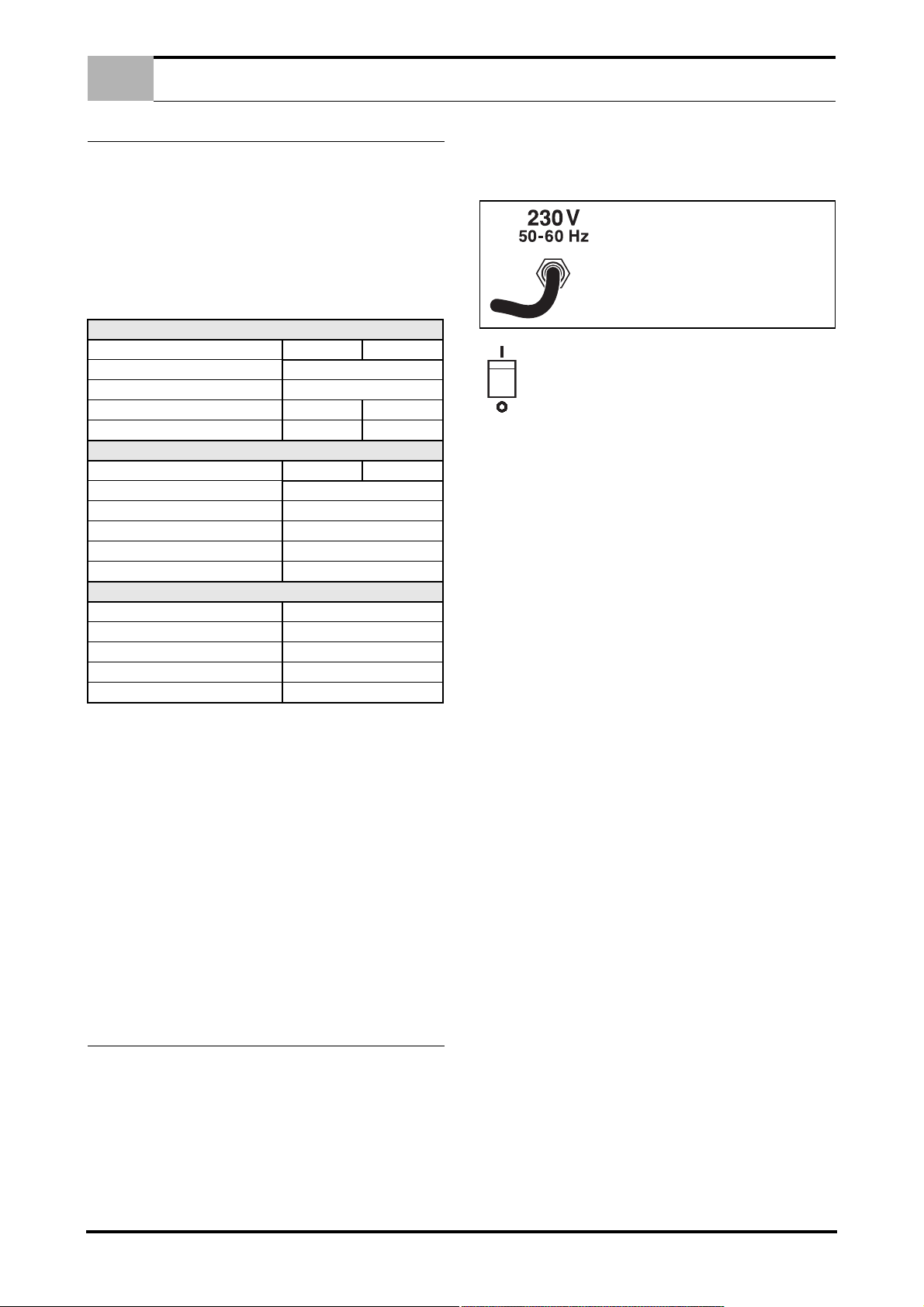
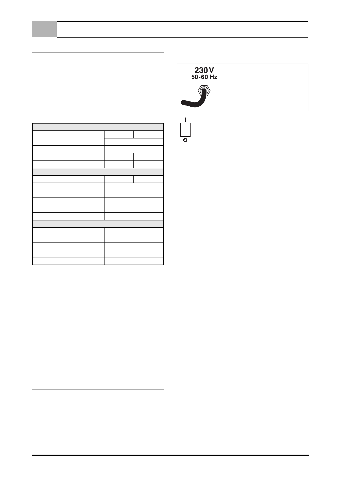
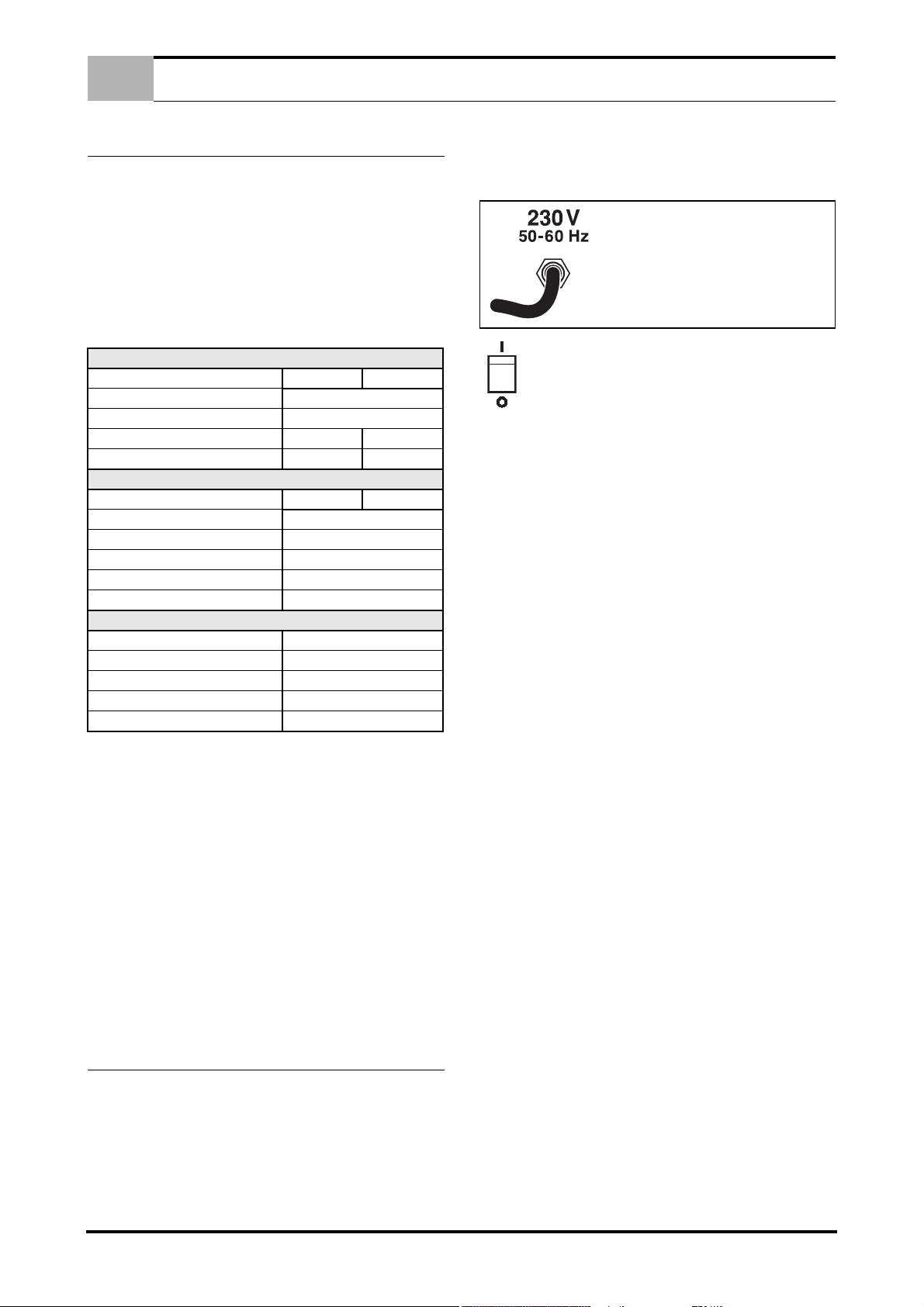
BEFORE INSERTING THE MAINS
PLUG, IN ORDER TO AVOID THE FAIL
OF POWER SOURCE, CHECK IF THE
MAINS CORRESPONDS TO THE
WISHED MAIN SUPPLY.
TECHNICAL DESCRIPTION
1.0 TECHNICAL DESCRIPTION
1.1 DESCRIPTION
The system consists of a modern direct current generator for the
welding of metals, developed via application of the inverter. This
special technology allows for the construction of compact light
weight generators with high performance. l’ts adjust ability, effeciency and energy consumption make it an excellent work tool
suitable for coated electrode and GTAW (TIG) welding.
1.2 TECHNICAL DATA
DATA PLATE
Single phase supply 230 V
Frequency 50 Hz / 60 Hz
Effective consuption 16A 12A
Maximum consuption 27A 20A
Open circuit voltage 85V
Welding current 5A ÷ 150A
Duty cycle 35% 150A
Duty cycle 60% 120A
Duty cycle 100% 100A
Protection class IP 23
Insulation class H
Weight Kg. 10
Dimensions mm 190 x 300 x 400
European Standards EN 60974.1 / EN 60974.10
IMPORTANT: MAKE SURE THE POWER SOURCE MEETS
THE ABOVE REQUISITES. EXCEEDING THE SPECIFIED
VOLTAGE CAN DAMAGE THE WELDING MACHINE AND INVALIDATE THE WARRANTY.
1.3 ACCESSORIES
Consult the area agents or the dealer.
1.4 DUTY CYCLE AND OVERHEATING
Duty cycle is the percentage of 10 minutes at 40°C ambient temperature that the unit can weld at its rated output without overheating. If the unit overheats, the output stops and the over
temperature light comes On. To correct the situation, wait fifteen
minutes for unit to cool. Reduce amperage, voltage or duty cycle
before starting to weld again (See page IV).
1.5 VOLT - AMPERE CURVES
Volt-ampere curves show the maximum voltage and amperage
output capabilities of the welding power source. Curves of other
settings fall under curves shown (See page IV).
PRIMARY
MMA TIG
SECONDARY
MMA TIG
2.0 INSTALLATION
IMPORTANT: BEFORE CONNECTING, PREPARING OR USING EQUIPMENT, READ SECTION 1.0 SAFETY PRECAUTIONS.
2.1 CONNECTING THE POWER SOURCE TO THE MAINS
ELECTRICITY SUPPLY.
SERIOUS DAMAGE TO THE EQUIPMENT MAY RESULT IF
THE POWER SOURCE IS SWITCHED OFF DURING WELDING
OPERATIONS.
The equipment is shipped without any plug installed. It works with
a wide range of 230 voltage ±10%. The recommended plug may
be applied checking that the power outlet is equipped with a fuse
capable of carrying the amperes indicated on the data plate on the
unit.
ON - OFF SWITCH
This switch has two positions: ON = I and OFF = O.
2.2 HANDLING AND TRANSPORTING THE POWER
SOURCE
OPERATOR SAFETY: WELDER’S HELMET - GLOWES SHOES WITH HIGH INSTEPS.
THE WELDING POWER SOURCE DO NOT WEIGHT MORE
THAN 25 KG AND CAN BE HANDLED BY THE OPERATOR.
READ WELL THE FOLLOWING PRECAUTIONS.
The machine is easy to lift, transport and handle, though the following procedures must always be observed:
1. The operations mentioned above can be operated by the
handle on the power source.
2. Always disconnect the power source and accessories from
main supply before lifting or handling operations.
3. Do not drag, pull or lift equipment by the cables.
2.3 CONNECTION AND PREPARATION OF EQUIPMENT
FOR STICK WELDING.
• TURN OFF WELDER BEFORE MAKING CONNECTIONS.
Connect all welding accessories securely to prevent power
loss. Carefully follow safety precautions described in section
1.0
1. Fit the selected electrode to the electrode clamp.
2. Connect the ground cable quick connection to the negative (-
) receptacle and locate the clamp near the welding zone.
3. Connect the electrode cable quick connection to the positive
(+) receptacle.
4. Use the above connection for straight polarity welding; for re-
verse polarity turn the connection.
5. On the unit preset for coated electrode welding (Rif.5 - Pic-
ture 1 Page 4.)
6. Adjust welding current with ampere selector. (Rif.3 - Picture
1 Page 4.) .
7. Turn on the power source.
2.4 CONNECTION AND PREPARATION OF EQUIPMENT
FOR GAS TUNGSTEN ARC WELDING (TIG).
• TURN OFF WELDER BEFORE MAKING CONNECTIONS.
Connect welding accessories securely to avoid power loss or
leakage of dangerous gases. Carefully follow the safety precautions described in section 1.0.
1. Fit the required electrode and nozzle to the electrode holder
(Check the protrusion and state of the electrode tip).
2. Connect the ground cable quick connection to the positive (+)
receptacle and the clamp near the welding zone.
3. Connect the electrode torch power cable connector to the
negative quick-connection terminal (-) and the torch push
button connector to the corresponding socket (Rif.10 - Picture 1 Page 4.) .
3 EN

FUNCTIONS
2
13
10
9
11
8
4
5
6
7
CAUTION: THE EARTH CABLE CONNECTOR AND THE
TORCH POWER CABLE CONNECTED AS ABOVE WILL RESULT IN STRAIGHT POLARITY WELDING. THIS GENERATOR
IS NOT SUITABLE FOR GTAW (TIG) WELDING WITH REVERSE POLARITY.
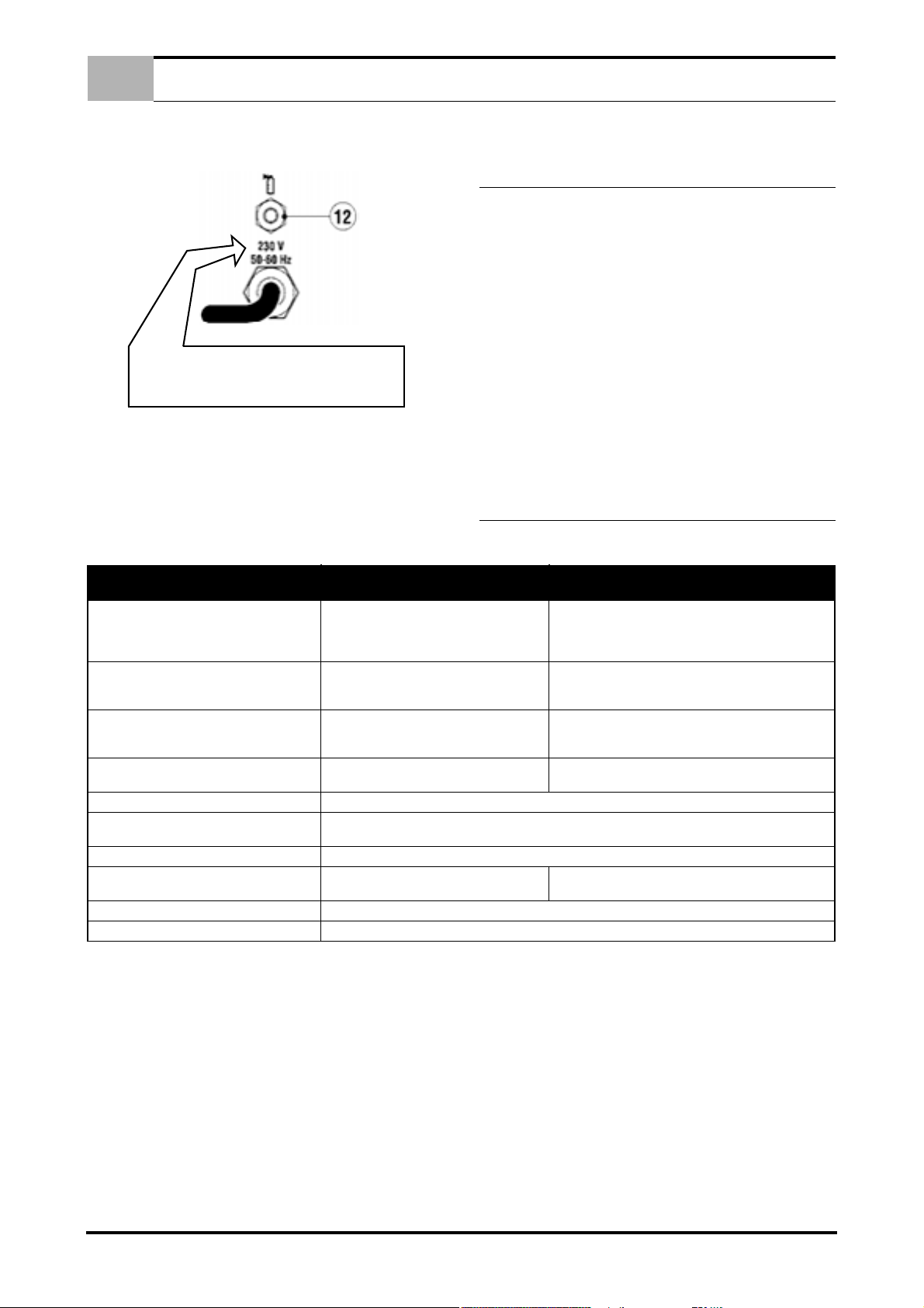
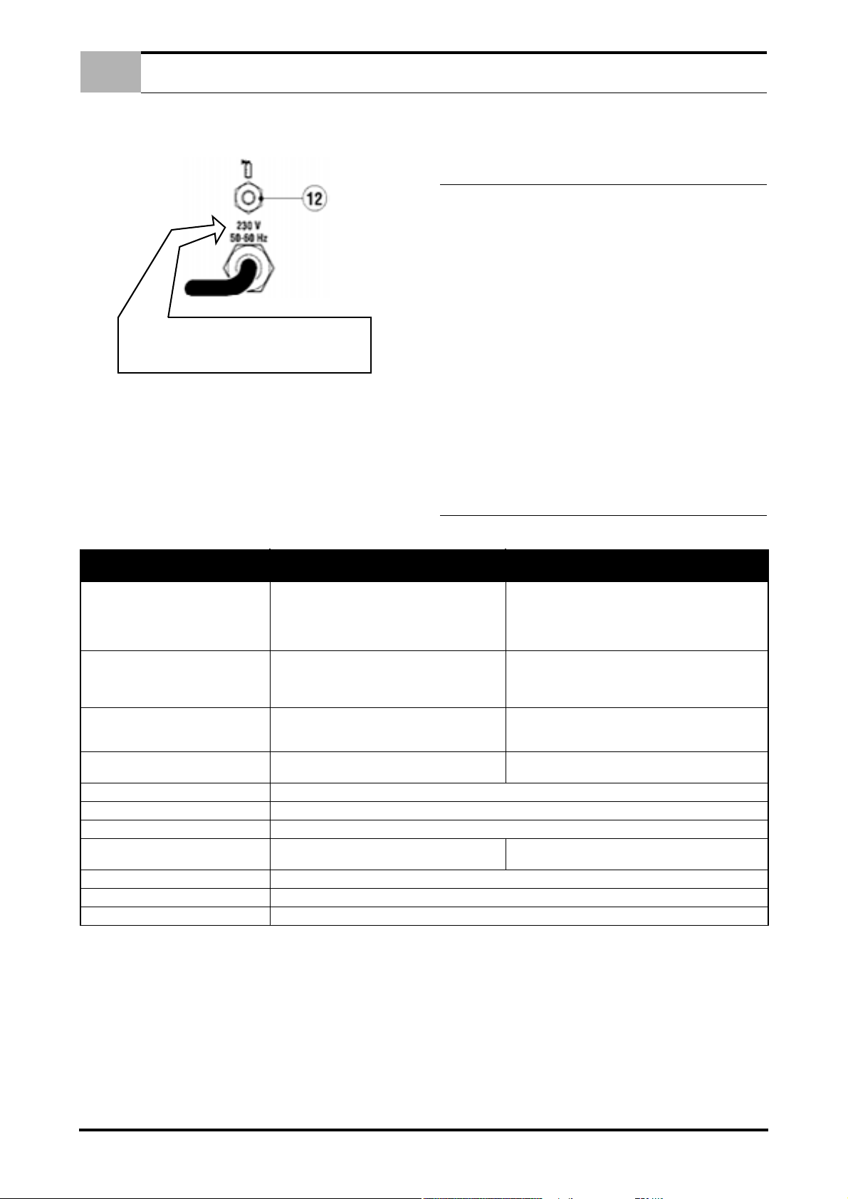
4. Insert the cylinder gas pipe into this fitting (Rif.12 - Picture 2
Page 5.) and secure with a hose clamp.
5. Connect the torch gas pipe to the gas outlet fitting (Rif.9 - Picture 1 Page 4.) (Front panel).
6. Press the illuminated switch to turn on the power source
(Rif.1 - Picture 1 Page 4.) .
7. Select the wants modality (Rif.5 - Picture 1 Page 4.) .
8. Check that there are no gas leaks.
9. Adjust welding current with amperes selector (Rif.3 - Picture
1 Page 4.) .
2.5 MANUAL GTAW (TIG) WELDING.
For manual TIG welding, set the welding mode selector (Rif.5 Picture 1 Page 4.) to position:
EN
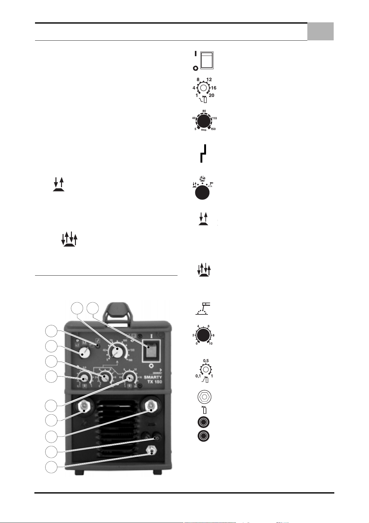
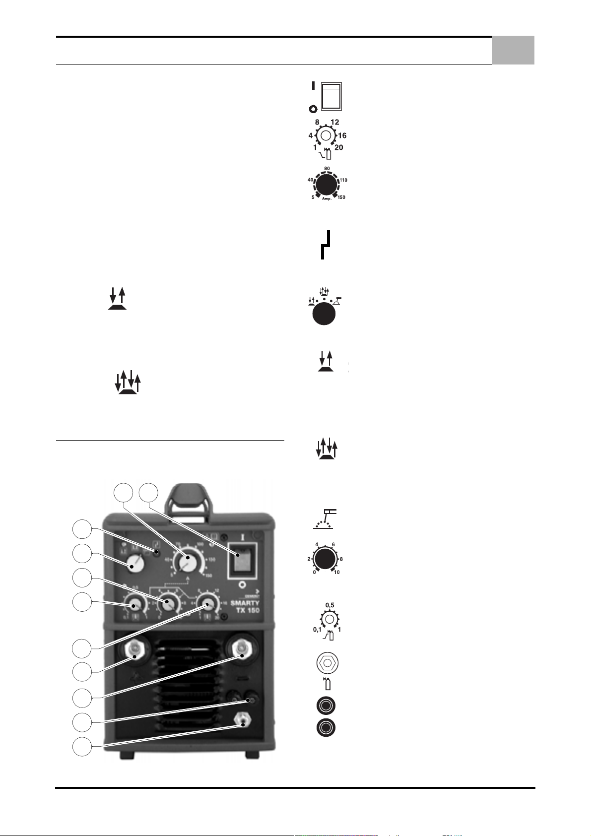
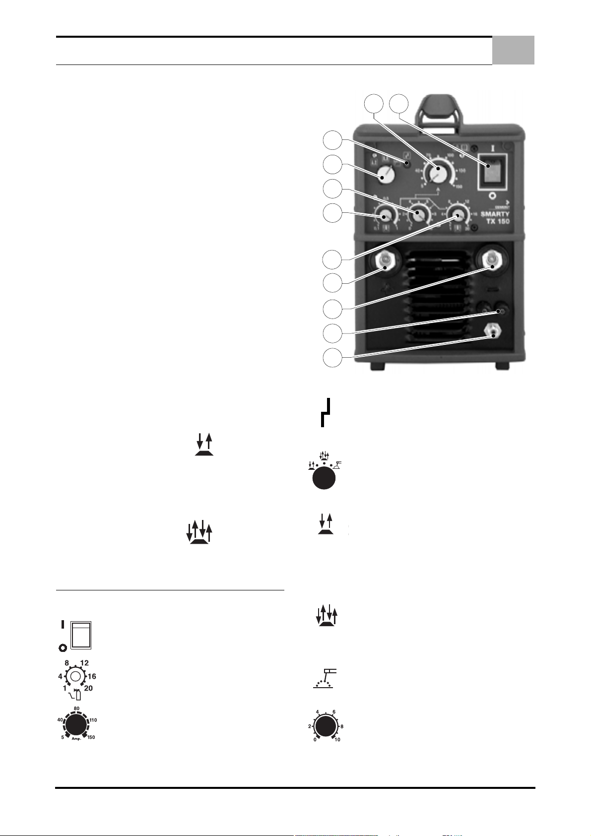
1 - ON - OFF SWITCH this switch (Rif.1 - Picture 1
Page 4.) has two positions: : I = ON - O = OFF.
2 - POST GAS REGULATION Regulation (Rif.2 Picture 1 Page 4.) of the delay time of the extinction
gas with screw-driver as regards the extinction of
the welding arc. Regulation time from 2 to 20 seconds.
3 - AMPERAGE SELECTOR Use control knob
(Rif.3 - Picture 1 Page 4.) to regulate welding current.
4 - OVERHEATING WARNING LIGHT The yellow
LED (Rif.4 - Picture 1 Page 4.) on the front panel indicates overheating due to an excessive duty cycle.
Interrupt welding operation; leave the power source
on until the lamp goes out, thereby signalling that
temperature has returned to normal.
Adjust the slope down duration with the time/slope down potentiometer (Rif.6 - Picture 1 Page 4.)
2.6 AUTOMATIC GTAW (TIG) WELDING.
For automatic TIG welding, set the welding mode selector (Rif.5 Picture 1 Page 4.) to position:
Adjust the slope down duration by means of the time/slope down
potentiometer (Rif.6 - Picture 1 Page 4.) .
3.0 FUNCTIONS
3.1 FRONT PANEL
Picture 1.
5 - WELDING MODE SELECTOR Select with the
switch (Rif.5 - Picture 1 Page 4.) the wished welding
modality .
Manual GTAW (TIG) welding
Appliance preset for GTAW (TIG) welding with slope
down. Press the torch push button to switch the
welding current on. When the pushbutton is released the current will gradually diminish until it
switches off.
Automatic GTAW (TIG) welding.
torch push button provides four functions.
The first time it is pressed, the gas flow is enabled
and when released the welding current comes on.
The second time the torch push button is pressed,
the slope down is enabled (welding current gradually diminishes until it switches off) and when released
the welding current is cut off.
Appliànce preset for coated electrode welding.
6 - SLOPE DOWN REGULATION
The regulation of (Rif.6 - Picture 1 Page 4.) slope
down time can be set continuosly from 0.2 to 10 seconds and works after the release of push-botton
torch.
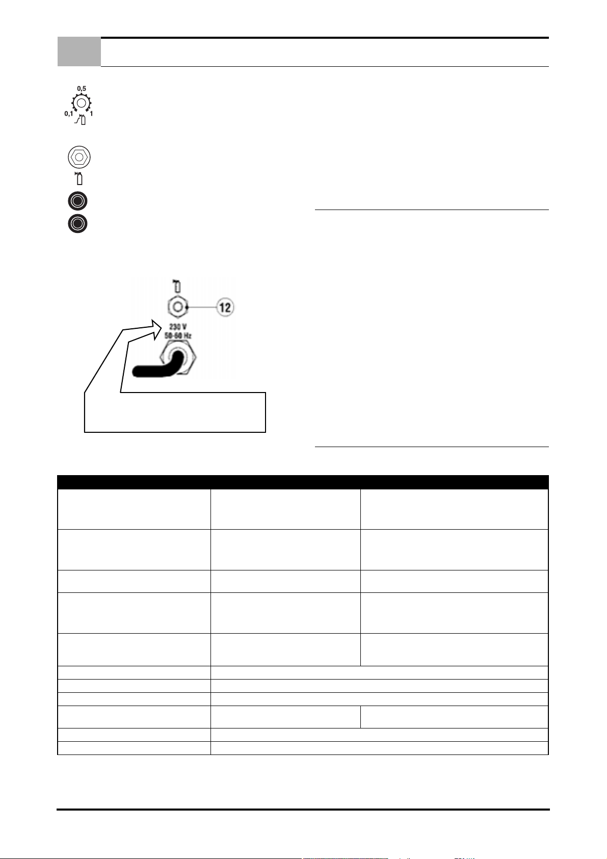
7 - PRE GAS REGULATION
Regulation (Rif.7 - Picture 1 Page 4.) of the delay
time of the arc primer with screw-driver as regards
the gas that has to arrive to the torch to protect the
welding bath. Regulation time from 0,1 to 1 second.
9 - GAS OUTLET FITTING
Connect the gas pipe leading (Rif.9 - Picture 1 Page
4.) to the electrode torch to this fitting and fully tighten.
10 - SOCKET TORCH PUSHBUTTON (Rif.10 - Picture 1 Page 4.) .
4 EN
EN
Example
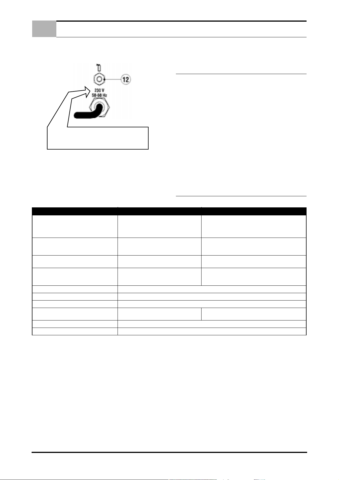
BEFORE INSERTING THE MAINS PLUG, IN ORDER
TO AVOID THE FAIL OF POWER SOURCE, CHECK
IF THE MAINS CORRESPONDS TO THE WISHED
MAIN SUPPLY.
MAINTENANCE
3.2 REAR PANEL
Picture 2.
put or short circuit that occurs during this phase is treated as a
fault and will cause the output power to be disabled.
4.0 MAINTENANCE
IMPORTANT: DISCONNECT THE POWER PLUG AND WAIT
AT LEAST 5 MINUTES BEFORE CARRYING OUT ANY MAINTENANCE. MAINTENANCE MUST BE CARRIED OUT MORE
FREQUENTLY IN HEAVY OPERATING CONDITIONS.
Carry out the following operations every three (3) months:
a. Replace any illegible labels.
b. Clean and tighten the welding terminals.
c. Replace damaged gas tubing.
d. Repair or replace damaged welding cables.
e. Have specialized personnel replace the power cable if dam-
aged.
Carry out the following operations every six (6) months:
1. Insert the cylinder gas pipe into this fitting (Rif.12 - Picture 2
Page 5.) and secure with a hose clamp.
Ensure that these connections are well tightened to avoid
power loss and overheating.
NB: the power source is fitted with an anti-sticking device that disables power if output short circuiting occurs or if the electrode
sticks, allowing it to be easily detached from the workpiece. This
device enters into operation when power is supplied to the generator, even during the initial checking period, therefore any load in-
TYPES OF MALFUNCTIONING
WELDING FAULTS
The generator does not weld: the digital switch
is not lit.
During welding suddenly the outgoing current
is interrupted, the the orange led goes on.
Welding power reduced.
Excessive jets.
Craters. Fast removal of the electrodes.
Inclusions.
Inadequate penetration. Forward speed too high. Welding current too low.
Sticking.
Blowing and porosity. Damp electrodes. Arch too long. Wrong torch polarity.
Jacks. Currents too high. Dirty materials.
POSSIBLE CAUSES CONTROLS AND REMEDIES
A) The main switch is off.
B) The power lead is interrupted (lack of one
or two phases).
C) Other.
Overheating has occurred and the automatic
protection has come on. (See work cycles).
Outgoing wires are not correctly attached.
A phase is missing.
Welding arch too long.
Welding current too high.
Inadequate cleaning and bad distribution of coating.
Faulty movement of the electrodes.
Welding arch too short.
Current too low.
Remove any dust inside the generator using a jet of dry air.
Carry out this operation more frequently when working in very
dusty places.
5.0 TYPES OF MALFUNCTIONING/ WELDING
FAULTS – CAUSES – REMEDIES
A) Switch on mains.
B) Verify and repair.
C) Ask for the intervention of the Assistance Centre.
Keep generator switched on and wait till temperature has
dropped again (10-15 minutes) to the point where the orange switch goes off again.
Check that wires are intact, that the pliers are sufficient
and that they are applied to welding surface clean from
rust, paint or oils.
Wrong torch polarity, lower the current values.
Increase current values.
5 EN

SOMMAIRE
1.0 DESCRIPTION DONNEES TECHNIQUES . . . . . . . . . . . . . . . . . . . . . . . . . . . . . . . . . . . . . . . . . . . . . . . . . . 2
1.1 DESCRIPTION . . . . . . . . . . . . . . . . . . . . . . . . . . . . . . . . . . . . . . . . . . . . . . . . . . . . . . . . . . . . . . . . . . 2
1.2 DONNEES TECHNIQUES . . . . . . . . . . . . . . . . . . . . . . . . . . . . . . . . . . . . . . . . . . . . . . . . . . . . . . . . . 2
1.3 ACCESSOIRES . . . . . . . . . . . . . . . . . . . . . . . . . . . . . . . . . . . . . . . . . . . . . . . . . . . . . . . . . . . . . . . . . . 2
1.4 FACTEUR DE MARCHE . . . . . . . . . . . . . . . . . . . . . . . . . . . . . . . . . . . . . . . . . . . . . . . . . . . . . . . . . . . 2
1.5 COURBES VOLT/AMPERE . . . . . . . . . . . . . . . . . . . . . . . . . . . . . . . . . . . . . . . . . . . . . . . . . . . . . . . . 2
2.0 INSTALLATION . . . . . . . . . . . . . . . . . . . . . . . . . . . . . . . . . . . . . . . . . . . . . . . . . . . . . . . . . . . . . . . . . . . . . . . 2
2.1 BRANCHEMENT DU GENERATEUR AU RESEAU . . . . . . . . . . . . . . . . . . . . . . . . . . . . . . . . . . . . . . 2
2.2 DEPLACEMENT ET TRANSPORT DU GENERATEUR . . . . . . . . . . . . . . . . . . . . . . . . . . . . . . . . . . . 2
2.3 BRANCHEMENT, PRÉPARATION DE L'APPAREIL POUR LE SOUDAGE A L'ÉLECTRODE EN-
ROBÉE. . . . . . . . . . . . . . . . . . . . . . . . . . . . . . . . . . . . . . . . . . . . . . . . . . . . . . . . . . . . . . . . . . . . . . . . . 2
2.4 BRANCHEMENT, PRÉPARATION DE L'APPAREIL POUR LE SOUDAGE TIG. . . . . . . . . . . . . . . . 2
FR
2.5 SOUDAGE GTAW (TIG) MANUEL . . . . . . . . . . . . . . . . . . . . . . . . . . . . . . . . . . . . . . . . . . . . . . . . . . . 3
2.6 SOUDAGE GTAW (TIG) AUTOMATIQUE. . . . . . . . . . . . . . . . . . . . . . . . . . . . . . . . . . . . . . . . . . . . . . 3
3.0 FONCTIONS . . . . . . . . . . . . . . . . . . . . . . . . . . . . . . . . . . . . . . . . . . . . . . . . . . . . . . . . . . . . . . . . . . . . . . . . . 3
3.1 PANNEAU AVANT . . . . . . . . . . . . . . . . . . . . . . . . . . . . . . . . . . . . . . . . . . . . . . . . . . . . . . . . . . . . . . . 3
3.2 PANNEAU ARRIERE . . . . . . . . . . . . . . . . . . . . . . . . . . . . . . . . . . . . . . . . . . . . . . . . . . . . . . . . . . . . . 4
4.0 ENTRETIEN . . . . . . . . . . . . . . . . . . . . . . . . . . . . . . . . . . . . . . . . . . . . . . . . . . . . . . . . . . . . . . . . . . . . . . . . . . 4
5.0 TYPE DE PANNE / DEFAUTS DE SOUDAGE - CAUSES - REMEDES . . . . . . . . . . . . . . . . . . . . . . . . . . . 4
PIÈCES DÉTACHÉES . . . . . . . . . . . . . . . . . . . . . . . . . . . . . . . . . . . . . . . . . . . . . . . . . . . . . . . . . . . . . . . . . . . I - III
SCHÉMA ÉLECTRIQUE . . . . . . . . . . . . . . . . . . . . . . . . . . . . . . . . . . . . . . . . . . . . . . . . . . . . . . . . . . . . . . . . . . . . .V
1 FR
FR
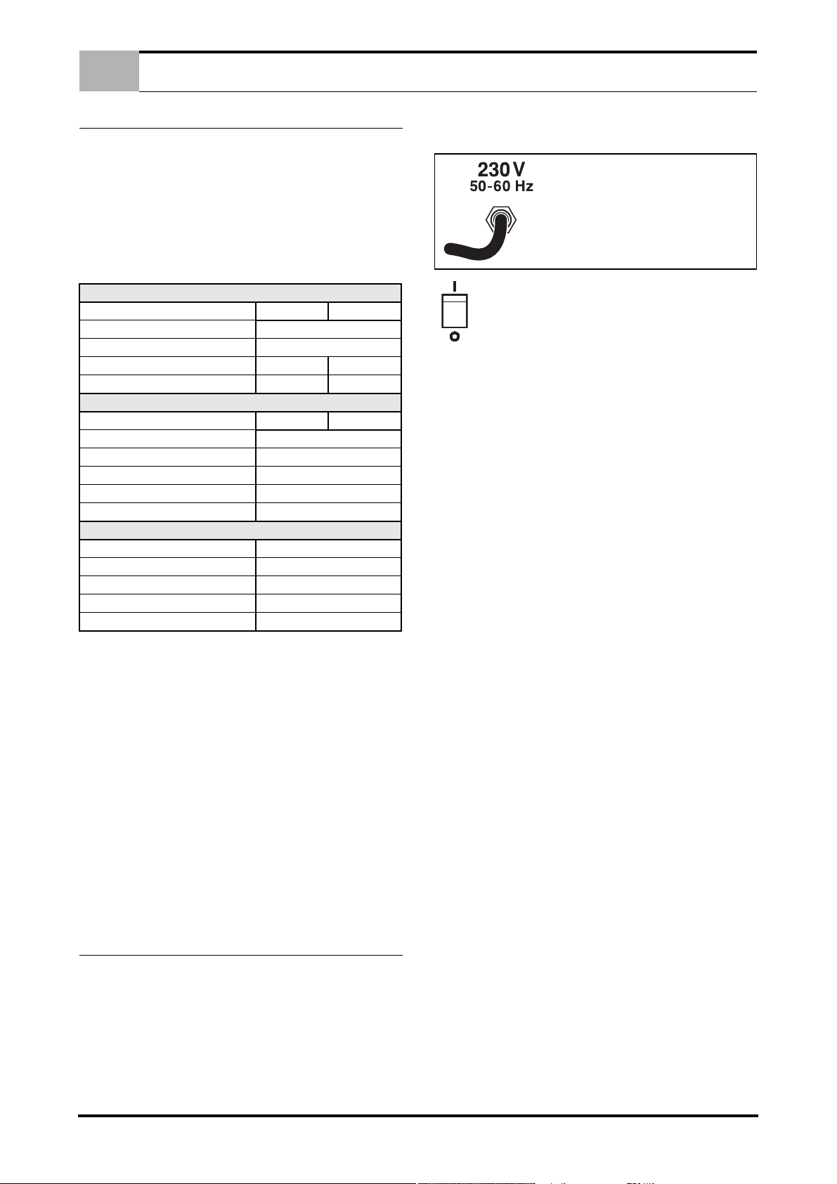
AFIN D'ÉVITER TOUT DOMMAGE A
L'APPAREIL, CONTRÔLER QUE LA
TENSION DU RÉSEAU CORRESPONDE
À CELLE DU GÉNÉRATEUR AVANT DE
BRANCHER LA PRISE D'ALIMENTATION.
DESCRIPTION DONNEES TECHNIQUES
1.0 DESCRIPTION DONNEES TECHNIQUES
1.1 DESCRIPTION
Ce générateur à courant continu moderne utilisé dans le soudage
des métaux est né grate à l’application électronique de l’onduleur.
Cette technologie spéciale a permis de construire des générateurs compacts, légers et très performants. Les possibilités de réglage, le rendement et la consommation d’énergie entêté optimisés
pourque ce générateur soit adapté au soudage à électrodes enrobées et GTAW (TIG).
1.2 DONNEES TECHNIQUES
Tension monophasé 230 V
Fréquence 50 Hz / 60 Hz
Consommation effective 16A 12A
Consommation maxi 27A 20A
Tension à vide 85V
Courant de soudage 5A ÷ 150A
Facteur de marche à 35% 150A
Facteur de marche à 60% 120A
Facteur de marche à 100% 100A
Indice de protection IP 23
Classe d’isolement H
Poids Kg. 10
Dimensions mm 190 x 300 x 400
Norme EN 60974.1 / EN 60974.10
IMPORTANT : VÉRIFIER QUE LA SOURCE D'ALIMENTATION
SATISFAIT LES EXIGENCES CI-DESSUS. LE DÉPASSEMENT
DE LA TENSION INDIQUÉE PEUT ENDOMMAGER LA SOUDEUSE ET ANNULER LA GARANTIE.
1.3 ACCESSOIRES
Consulter les agents de zone ou le revendeur.
1.4 FACTEUR DE MARCHE
Le facteur de marche est le pourcentage de temps sur 10 minutes
pendant lequel le poste peut fonctionner en charge sans surchauffer, en considerant une température ambiante de 40°,C,
sans l’intervention du thérmostat.
Si le poste surchauffe, le courant de sortie s'arrête et le voyant de
surchauffe s'allume. Laisser le poste refroidir pendant quinze minutes. Réduire l'intensité du courant de soudage, sa tension ou le
cycle de travail avant d'opérer à nouveau (Voir page IV).
1.5 COURBES VOLT/AMPERE
Les courbes Volt/Ampere indiquent l'intensité et la tension maximales du courant de soudage généré par le poste (Voir page IV).
PRIMAIRE
MMA TIG
SECONDAIRE
MMA TIG
2.0 INSTALLATION
IMPORTANT: AVANT DE RACCORDER, DE PRÉPARER OU
D'UTILISER LE GÉNÉRATEUR, LIRE ATTENTIVEMENT LE
CHAPITRE 1.0 SECURITÉ.
2.1 BRANCHEMENT DU GENERATEUR AU RESEAU
L’EXTINCTION DU GÉNÉRATEUR EN PHASE DE SOUDAGE
PEUT PROVOQUER DE GRAVES DOMMAGES À L’APPAREIL.
S’assurer que la prise d’alimentation est équipée du fusible indiqué sur le tableau des données techniques placé sur le générate-
ur. Tous les modèles de générateur prévoient une compensation
des variations de réseau. Pour chaque variation de ± 10%, on obtient une variation du courant de soudage de ±0,2%.
INTERRUPTEUR D’ALLUMAGE: terrupteur possède
deux positions I = ALLUME - O = ETEINT.
2.2 DEPLACEMENT ET TRANSPORT DU GENERATEUR
PROTECTION DE L'OPERATEUR: CASQUE - GANTS -
CHAUSSURES DE SÉCURITÉ.
SON POIDS NE DÉPASSANT PAS LES 25 KG, LA SOUDEUSE
PEUT ÊTRE SOULEVÉE PAR L'OPÉRATEUR. LIRE ATTENTIVEMENT LES PRESCRIPTIONS SUIVANTES.
L’appareil a été conçu pour être soulevé et transporté. Ce transport
est simple mais doit être fait dans le respect de certaines règles:
1. Ces opérations peuvent être faites par la poignée se trouvant
sur le générateur.
2. Avant tout déplacement ou levage, débrancher l’appareil et
tous ses accessoires du réseau.
3. L'appareil ne doit pas être remorqué, traîné ou soulevé à
l'aide des câbles électriques.
2.3 BRANCHEMENT, PRÉPARATION DE L'APPAREIL
POUR LE SOUDAGE A L'ÉLECTRODE ENROBÉE.
• ETEINDRE LE POSTE AVANT DE PROCÉDER AUX
CONNEXIONS
Raccorder avec soin les accessoires de soudage afin d’éviter les
pertes de puissance. Respecter scrupuleusement les règles de
sécurité chapitre 1.0.
1. Placer l'électrode à utiliser dans la pince du porte-électrodes.
2. Raccorder le câble de masse à la borne négative (-) et placer
la pince de masse à proximité de la zone à souder.
3. Raccorder le câble du porte-électrodes à la borne positive
(+).
4. Le raccordement des deux câbles effectué comme indiqué
ci-dessus donnera un soudage à polarité directe. Pour un
soudage à polarité inverse, intervertir les connexions des
deux câbles.
5. Positionner le sélecteur de modalité sur le type de soudage
à électrodes enrobées (Rif.5 - Figure 1 Pag. 3.) .
6. Régler la courant de soudage nécessaire à l'aide du bouton
(Rif.3 - Figure 1 Pag. 3.) .
7. Allumer le génerateur en tournant le bouton démarrage - arrêt.
2.4 BRANCHEMENT, PRÉPARATION DE L'APPAREIL
POUR LE SOUDAGE TIG.
2.5 • ETEINDRE LE POSTE AVANT DE PROCÉDER AUX
CONNEXIONS
Raccorder les accessoires de soudage avec soin afin d’éviter des
pertes de puissance ou des fuites de gaz dangereuses. Respecter scrupuleusement les règles de sécurité chapitre 1.0.
1. Monter l'électrode et le diffuseur de gaz choisis sur la torche
(Contrôler la saillie et l'état de la pointe de l'électrode).
2. Raccorder le câble de masse à la borne positive (+) et placer
la pince de masse à proximité de la zone à souder.
3. Raccorder le connecteur du câble de puissance de la torche
à la borne rapide négative (-). Raccorder le connecteur du
bouton torche à la prise relative (Rif.10 - Figure 1 Pag. 3.)
2 FR
FONCTIONS
2
13
10
9
11
8
4
5
6
7
FR
ATTENTION: LES CONNECTEURS DU CÂBLE DE TERRE ET
DU CÂBLE DE PUISSANCE TORCHE AINSI CONNECTÉS
DONNERONT COMME RÉSULTAT UNE SOUDURE AVEC POLARITÉ DIRECTE. CE GÉNÉRATEUR N'EST PAS ADAPTÉ
POUR FONCTIONNER EN SOUDAGE GTAW (TIG) AVEC POLARITÉ INVERSE.
4. Enfiler dans ce raccord (Rif.12 - Figure 2 Pag. 4.) le tuyau du
gaz provenant de la bouteille et le bloquer avec un collier de
serrage.
5. Raccorder le tuyau du gaz de la torche au raccord sortie gaz
(Gaz out) (Rif.9 - Figure 1 Pag. 3.) (Panneau avant).
6. Allumer le générateur en actionnant l'interrupteur lumineux
(Rif.1 - Figure 1 Pag. 3.) .
7. Sélectionner le mode de soudage désiré (Rif.5 - Figure 1 Pag. 3.).
8. Contrôler qu'il n'y a pas de fuites de gaz.
9. Sélectionne la quantité de courant nécessaire pour le soudage (Rif.3 - Figure 1 Pag. 3.) .
2.6 SOUDAGE GTAW (TIG) MANUEL.
Pour obtenir la condition de soudage TIG manuel, positionner le
sélecteur mode de soudage (Rif.5 - Figure 1 Pag. 3.) dans la position
Régler la durée du temps de descente avec le potentiomètre régulateur time/slope down (Rif.6 - Figure 1 Pag. 3.) .
2.7 SOUDAGE GTAW (TIG) AUTOMATIQUE.
Pour obtenir la condition de soudage TIG automatique, positionner le sélecteur mode de soudage (Rif.5 - Figure 1 Pag. 3.) dans
la position
Régler la durée du temps de descente avec le potentiomètre régulateur time/slope down (Rif.6 - Figure 1 Pag. 3.) .
3.0 FONCTIONS
3.1 PANNEAU AVANT
Figure 1.
1 - INTERRUPTEUR DE MISE EN MARCHE Cet interrupteur (Rif.1 - Figure 1 Pag. 3.) a deux positions
: I = MARCHE - O = ARRÊT.
2 - RÉGLAGE POST-GAZ Réglage (Rif.2 - Figure 1
Pag. 3.) du retardement de la coupure du gaz par
rapport à l'extinction de l'arc de soudage. Temps
réglable de 2 à 20 secondes
3 - SÉLECTEUR AMPÉRAGE Sélectionne (Rif.3 Figure 1 Pag. 3.) la quantité de courant nécessaire
pour le soudage.
4 - VOYANT DE SURCHAUFFAGE L'allumage de
la led jaune (Rif.4 - Figure 1 Pag. 3.) située sur le
panneau avant indique une surchauffe de l’appareil
causée par une surcharge de travail. Dans ce cas,
interrompre le soudage en maintenant le générateur
allumé jusqu’à extinction du témoin qui indiquera
une normalisation de la température.
5 - SÉLECTEUR MODALITÉ DE SOUDAGE Sélectionner le type de fonctionnement désiré (Rif.5 Figure 1 Pag. 3.) .
Soudage GTAW (TIG) manuel.
appareillage prévu pour le soudage TGAW (TIG)
avec rampe de descente (Slope Down). Appuyer
sur le bouton poussoir de la torche pour declencher
le courant de soudage. En relachant le bouton poussoir, on aura une diminution progressive du courant
(descente) jusqu'à l'extinction.
Soudage GTAW (TIG) automatique.
Le bouton poussoir torche fonctionne à 4 effets. La
première pression sur le bouton torche introduit le
débit du gaz; quand on le relâche, on declenche le
courant de soudage.La deuxième pression sur ce
même bouton declenche la rampede descente (diminution progressive du courant de soudage jusqu'à l'extinction); quand on le relâche, on interrompt
le courant de soudage.
Appareillage prévu pour le soudage à électrodes
enrobées.
6 - RÉGLAGE SLOP/DOWN
La fonction de ce réglage (Rif.6 - Figure 1 Pag. 3.)
(Slope Down)programmable de 0.2 à 10 secondes,
est d'ajuster de façon continue la durée du temps
d'évanouissement de l'arc après le relâchement de
la gâchette de la torche.
7 - RÉGLAGE PRÉ-GAZ
Réglage (Rif.7 - Figure 1 Pag. 3.) du retardement
de l'allumage de l'arc par rapport à la sortie du gaz
qui doit arriver à la torche pour protéger le bain de
fusion. Temps réglable de 0,1 à 1 seconde.
9 - RACCORD DE SORTIE DU GAZ
Brancher sur ce raccord (Rif.9 - Figure 1 Pag. 3.) le
tuyau conduisant le gaz à la torche et serrer à fond.
10 - PRISE BOUTON DE TORCHE (Rif.11 - Figure
1 Pag. 3.) .
3 FR

FR
ENTRETIEN
3.2 PANNEAU ARRIERE
Figure 2.
Exemple
AFIN D’ÉVITER TOUT DOMMAGE A L’APPAREIL,
CONTROLE QUE LA TENSION DU RÉSEAU CORRESPONDE À CELLE DU GÉNÉRATEUR AVANT DE
BRANCHER LA PRISE D’ALIMENTATION.
1. Insérer dans ce raccord (Rif.12 - Figure 2 Pag. 4.) le tube de
gaz provenant de la bouteille et le serrer avec un collier.
Le serrage défectueux de ces deux raccordements pourra
donner lieu à des pertes de puissance et des surchauffes.
NB: Le genérateur est équipe d’un dispositif (anti- accrochage)
qui inhibe la puissance en cas de courtcircuit en sortie ou au cas
où l’électrode se serait collée. Il permet également de détacher
l’électrode de la piece. Ce dispositif entre en action lorsque l’on
alimente le génerateur. Par conséquent, il fonctionne dès la période initiale de vérifi-cation ce qui fait que toute charge et tout
coutt-circuit qui se déclencherait au tours de cette période serait
consideré comme une anomalie et impliquerait l’inhibition de la
puissance en sotiie.
4.0 ENTRETIEN
ATTENTION: DÉBRANCHER LA FICHE D'ALIMENTATION ET
ATTENDRE 5 MINUTES AVANT TOUTE INTERVENTION D'ENTRETIEN. LA FRÉQUENCE D'ENTRETIEN DOIT ÊTRE AUGMENTÉE EN CONDITIONS DIFFICILES.
Tous les trois (3) mois effectuer les opérations suivantes:
a. Remplacer les étiquettes illisibles.
b. Nettoyer et serrer les terminaux de soudage.
c. Remplacer les tuyaux de gaz endommagés.
d. Réparer ou remplacer les câbles de soudage endommagés.
e. Faire remplacer par un personnel spécialisé le câble d'alimen-
tation en cas de dommages.
Tous les six (6) mois effectuer les opérations suivantes:
Nettoyer de la poussière l'intérieur du générateur à l'aide d'un jet
d'air sec.
Augmenter la fréquence de cette opération lors d'un travaiI en environnement très poussiéreux.
5.0 TYPE DE PANNE / DEFAUTS DE SOUDAGE CAUSES - REMEDES
TYPE DE PANNE
DEFAUT DE SOUDAGE
Le générateur ne soude pas : l'instrument numérique n'est pas allumé
Au cours du soudage, le courant est soudainement coupé à la sortie. La LED jaune s'allume.
Puissance de soudage réduite.
Eclats excessifs.
Cratères. Eloignement rapide de l'électrode au détachement.
Inclusions. Mauvais nettoyage ou distribution erronée des passages. Mouvement défectueux de l'électrode.
Pénétration insuffisante. Vitesse d'avance trop forte. Courant de soudage trop faible.
Collages.
Soufflures et porosité. Electrodes humides. Arc trop long. Polarité incorrecte de la torche.
Criques. Courants trop forts. Matériaux sales.
CAUSES POSSIBLES CONTRÔLES ET RIMEDES
A) L’interrupteur général est éteint.
B) Câble d'alimentation coupé (une ou plusieurs phases manquantes).
C) Autres.
Une surchauffe a eu lieu et la protection technique est intervenue (Voir les cycles de travail).
Câbles de raccordement mal branchés.
Une phase est absente.
Arc de soudage trop long.
Courant de soudage trop fort.
Arc de soudage trop court.
Courant trop faible.
A) Allumer l'interrupteur général.
B) Contrôler et intervenir.
C) Faire contrôler par le Centre d'Assistance.
Laisser le générateur allumé et attendre qu'il se refroidisse
(10-15 minutes) jusqu'à ce que la protection se rétablisse
et que la LED jaune s'éteigne.
S'assurer que les câbles sont en bon état, que la pince de
masse est suffisante et qu'elle est appliquée sur la pièce à
souder propre et sans traces de rouille, de peinture ou de
graisse.
Polarité incorrecte de la torche.
Augmenter la valeur de courant programmée
4 FR

SUMARIO
1.0 DATOS TÉCNICOS . . . . . . . . . . . . . . . . . . . . . . . . . . . . . . . . . . . . . . . . . . . . . . . . . . . . . . . . . . . . . . . . . . . . 2
1.1 DESCRIPCIÓN . . . . . . . . . . . . . . . . . . . . . . . . . . . . . . . . . . . . . . . . . . . . . . . . . . . . . . . . . . . . . . . . . . 2
1.2 ESPECIFICACIONES . . . . . . . . . . . . . . . . . . . . . . . . . . . . . . . . . . . . . . . . . . . . . . . . . . . . . . . . . . . . . 2
1.3 ACCESORIOS . . . . . . . . . . . . . . . . . . . . . . . . . . . . . . . . . . . . . . . . . . . . . . . . . . . . . . . . . . . . . . . . . . . 2
1.4 CICLO DE TRABAJO . . . . . . . . . . . . . . . . . . . . . . . . . . . . . . . . . . . . . . . . . . . . . . . . . . . . . . . . . . . . . 2
1.5 CURVAS VOLTIOS - AMPERIOS . . . . . . . . . . . . . . . . . . . . . . . . . . . . . . . . . . . . . . . . . . . . . . . . . . . . 2
2.0 INSTALACIÓN . . . . . . . . . . . . . . . . . . . . . . . . . . . . . . . . . . . . . . . . . . . . . . . . . . . . . . . . . . . . . . . . . . . . . . . . 2
2.1 ACOMETIDA DEL GENERADOR A LA RED . . . . . . . . . . . . . . . . . . . . . . . . . . . . . . . . . . . . . . . . . . . 2
2.2 TRANSPORTE DEL GENERADOR . . . . . . . . . . . . . . . . . . . . . . . . . . . . . . . . . . . . . . . . . . . . . . . . . . 2
2.3 PREPARACIÓN DEL EQUIPO PARA LA SOLDADURA CON ELECTRODO REVESTIDO . . . . . . . 2
2.4 PREPARACIÓN DEL EQUIPO PARA LA SOLDADURA GTAW ( TIG ) . . . . . . . . . . . . . . . . . . . . . . . 2
2.5 SOLDADURA GTAW (TIG) MANUAL . . . . . . . . . . . . . . . . . . . . . . . . . . . . . . . . . . . . . . . . . . . . . . . . . 3
ES
2.6 SOLDADURA GTAW (TIG) AUTOMÁTICA . . . . . . . . . . . . . . . . . . . . . . . . . . . . . . . . . . . . . . . . . . . . . 3
3.0 FUNCIONES . . . . . . . . . . . . . . . . . . . . . . . . . . . . . . . . . . . . . . . . . . . . . . . . . . . . . . . . . . . . . . . . . . . . . . . . . 3
3.1 PANEL FRONTAL . . . . . . . . . . . . . . . . . . . . . . . . . . . . . . . . . . . . . . . . . . . . . . . . . . . . . . . . . . . . . . . . 3
3.2 PANEL TRASERO . . . . . . . . . . . . . . . . . . . . . . . . . . . . . . . . . . . . . . . . . . . . . . . . . . . . . . . . . . . . . . . 4
4.0 MANTENIMIENTO . . . . . . . . . . . . . . . . . . . . . . . . . . . . . . . . . . . . . . . . . . . . . . . . . . . . . . . . . . . . . . . . . . . . . 4
5.0 FALLO O DEFECTO DE SOLDADURA - CAUSAS POSIBLES – SOLUCIÓNS . . . . . . . . . . . . . . . . . . . . 4
LISTA DE LAS PIEZAS DE RECAMBIO . . . . . . . . . . . . . . . . . . . . . . . . . . . . . . . . . . . . . . . . . . . . . . . . . . . . . . I - III
ESQUEMA ELÉCTRICO . . . . . . . . . . . . . . . . . . . . . . . . . . . . . . . . . . . . . . . . . . . . . . . . . . . . . . . . . . . . . . . . . . . . . V
1 ES
ES
ANTES DE INSERTAR LA CLAVIJA DEL
GENERADOR EN LA TOMA DE CORRIENTE HAY QUE COMPROBAR SI LA
RED TIENE EL VOLTAJE QUE NECESITA EL GENERADOR.
DATOS TÉCNICOS
1.0 DATOS TÉCNICOS
1.1 DESCRIPCIÓN
La instalación es un moderno generador de corriente continua
para soldar metales, creado gracias a la aplicación del inverter.
Esta particular tecnología ha permitido la fabricación de generadores compactos y ligeros, con prestaciones de gran nivel. La posibilidad de efectuar regulaciones, su rendimiento y consumo de
energía lo convierten en un excelente medio de trabajo,to para
soldaduras con electrodo revestido y GTAW (TIG).
1.2 ESPECIFICACIONES
TABLA TÉCNICA
Alimentación monofásica 230 V
Frequencia 50 Hz / 60 Hz
Consumición eficaz 16A 12A
Consumición máxima 27A 20A
Tensión en vacío 85V
Corriente de soldadura 5A ÷ 150A
Ciclo de trabajo a 35% 150A
Ciclo de trabajo a 60% 120A
Ciclo de trabajo a 100% 100A
Grado de protección IP 23
Clase de aislamiento H
Peso Kg. 10
Dimensiones mm 190 x 300 x 400
Normative EN 60974.1 / EN 60974.10
IMPORTANTE: COMPROBAR QUE LA FUENTE DE ALIMENTACIÓN CUMPLA DICHOS REQUISITOS. TENSIONES MAYORES QUE LA INDICADA PUEDEN DAÑAR LA SOLDADORA
E INVALIDAR LA GARANTÍA.
1.3 ACCESORIOS
Ponerse en contacto con los agentes de zona o con el distribuidor.
1.4 CICLO DE TRABAJO
El ciclo de trabajo es el porcentaje de un intervalo de 10 minutos
en el que la soldadora puede soldar a la corriente nominal con
una temperatura ambiente de 40 °C sin que se dispare la protección termostática. Si la protección se dispara hay que dejar enfriar
la soldadora por lo menos 15 minutos y bajar el amperaje o acortar el ciclo antes de retomar el trabajo (A ver pag. IV).
1.5 CURVAS VOLTIOS - AMPERIOS
Las curvas voltios-amperios indican la máxima corriente y la
máxima tensión de salida que ofrece la soldadora (A ver pag. IV).
PRIMARIO
MMA TIG
SECUNDARIA
MMA TIG
2.0 INSTALACIÓN
IMPORTANTE: ANTES DE CONECTAR, PREPARAR O UTILIZAR EL EQUIPO, LEA CUIDADOSAMENTE EL CAPÍTULO
1.0 NORMAS DE SEGURIDAD.
2.1 ACOMETIDA DEL GENERADOR A LA RED
DESCONECTAR LA SOLDADORA DURANTE LA SOLDADU-
RA PUEDE CAUSAR SERIOS DAÑOS AL EQUIPO.
Compruebe si Ia toma de corriente dispone del fusible que se indica en Ia tabla técnica del generador. Todos los modelos de ge-
nerador necesitan que se compensen las oscilaciones de voltaje.
A una oscilación de ± 10% corresponde una variación de Ia corriente de soldadura de ± 0,2%.
INTERRUPTOR DE ALIMENTACIÓN
Este interruptor tiene dos posiciones: I = ENCENDIDO
/ O = APAGADO.
2.2 TRANSPORTE DEL GENERADOR
PROTECCIÓN DEL SOLDADOR: CASCO - GUANTES CALZADO DE PROTECCIÓN.
LA SOLDADORA TIENE UN PESO MÁXIMO DE 25 KG Y
PUEDE SER LEVANTADA POR EL SOLDADOR. LEER ATENTAMENTE LAS PÁGINAS QUE SIGUEN.
Este equipo está diseñado para poder ser elevado y transportado.
La operación de transporte es sencilla pero se debe realizar de
acuerdo con las reglas siguientes:
1. Tomar la soldadora por el asa del generador.
2. Antes de elevarla y desplazarla hay que desconectarla de la
red y desconectar todos los accesorios.
3. No elevar, arrastrar o tirar del equipo por los cables de alimentación o de los accesorios.
2.3 PREPARACIÓN DEL EQUIPO PARA LA SOLDADURA
CON ELECTRODO REVESTIDO .
• APAGAR LA SOLDADORA ANTES DE CONECTARLA.
Conectar los accesorios de soldadura con sumo cuidado
para evitar pérdidas de potencia. Cumplir las normas de seguridad indicadas en el capitulo 1.0.
1. Montar el electrodo deseado en la pinza portaelectrodo.
2. Conectar el conector del cable de masa al borne rápido negativo (-) y la pinza del mismo cerca de la zona a soldar.
3. Conectar el conector de la pinza porta-electrodos al borne
rápido positivo (+).
4. Con esta disposición se obtiene una soldadura con polaridad
directa; para obtener la polaridad inversa hay que invertir las
conexiones.
5. Poner el selector de modo (Rif.5 - Figura 1 Página 3.) en soldadura con electrodos revestidos
6. Ajustar el amperaje de soldadura moviendo el selector de
amperaje (Rif.3 - Figura 1 Página 3.) .
7. Encender el generador girando el conmutador de encendido.
2.4 PREPARACIÓN DEL EQUIPO PARA LA SOLDADURA
GTAW ( TIG ) .
• APAGAR LA SOLDADORA ANTES DE CONECTARLA.
Conectar los accesorios de soldadura con sumo cuidado
para evitar pérdidas de potencia y fugas de gas. Cumplir las
normas de seguridad indicadas en el capítulo 1.0.
1. Montar en el porta-electrodos el electrodo y la boquilla de
gas seleccionados (Observar cuánto sobresale la punta del
electrodo y en qué estado se encuentra).
2. Conectar el conector del cable de masa al borne rápido positivo (+) y la pinza del mismo cerca de la zona por soldar.
3. Conectar el conector del cable de potencia del portaelectrodo a la conexión rápida negativa (-). Conectar el conector del
pulsante portalectrodo a la toma relativa (Rif.10 - Figura 1
Página 3.) .
2 ES

FUNCIONES
2
13
10
9
11
8
4
5
6
7
ES
ATENCION: EL CONECTOR DEL CABLE DE MASA Y EL DE
POTENCIA-PORTAELECTRODO CONECTADOS DE ESTA
MANERA DARÀN COME RESULTADO UNA SOLDADURA
CON POLARIDAD DIRECTA. ESTE GANARADOR NO ES ADECUADO PARA FUNCIONAR EN SOLADADURA TGAW (TIG)
CON POLARIDAD INVERTIDA.
4. Conectar en este empalme el tubo de gas procedente de la
bombola (Rif.12 - Figura 2 Página 4.) y apretarlo con abrazadera.
5. Conectar el tubo de gas del portaelectrodo al empalme de
salida de gas (Gas out) (Tablero delatero) (Rif.9 - Figura 1
Página 3.) .
6. Encender el ganerador apretando el pulsador luminoso (Rif.1
- Figura 1 Página 3.) .
7. Colocar el selector modalidad en el tipo de soldadura elegida
(Rif.5 - Figura 1 Página 3.) .
8. Controlar que no haya pérdida de gas.
9. Regular el amperaje de corriente de soldadura mediante el
selector de amperaje (Rif.3 - Figura 1 Página 3.) .
2.5 SOLDADURA GTAW (TIG) MANUAL.
Para obtener la condición de soldadura a TIG manual, colocar el
selector de modalidad de soldadura (Rif.5 - Figura 1 Página 3.)
en la posición correspondiente.
Regular el tiempo de bajada con el potenciómetro regulador time/
slope down (Rif.6 - Figura 1 Página 3.) .
2.6 SOLDADURA GTAW (TIG) AUTOMÁTICA.
Para obtener la condición de soldadura a TIG automática, colocar
el selector de modalidad de soldadura (Rif.5 - Figura 1 Página 3.)
en la posición correspondiente.
Regular el tiempo de bajada con el potenciómetro regulador time/
slope down (Rif.6 - Figura 1 Página 3.) .
3.0 FUNCIONES
3.1 PANEL FRONTAL
Figura 1.
1 - INTERRUPTOR DE ENCENDIDO Este interruptor (Rif.1 - Figura 1 Página 3.) puede colocarse en
dos posiciones: I = ENCENDIDO - O = APAGADO.
2 - REGULADOR POST GAS Regulación (Rif.2 Figura 1 Página 3.) del tiempo de retraso de la interrupción del gas con respecto a la interrupción del
arco de soldadura. Tiempo regulable de 2 a 20 segundos.
3 - SELECTOR AMPERAJE Seleccionar por medio
del botón esférico (Rif.3 - Figura 1 Página 3.) la
cantidad de corriente necesaria para la soldadura.
4 - PILOTO RECALENTAMIENTO El
indicador amarillo (Rif.4 - Figura 1 Página 3.) situado
en el panel delantero indica un recalentamiento del
equipo a causa de un ciclo de trabajo sobrante. En
este caso interrumpir la soldadura, dejando arrancado
el generador, hasta que el indicador que señala la normalización de la temperatura se apague
5 - SELECTOR MODALIDAD DE SOLDADURA
Seleccionar mediante el botón (Rif.5 - Figura 1 Página 3.) la modalidad de soldadura deseada.
Soldadura GTAW (TIG) manual
Equipo predispuesto para soldadura GTAW (TIG)
con rampa de bajada (Slope Down).
Presionar el pulsador portaelectrodo para encender
el equipo; soltando el pulsador, la corriente de soldadura disminuirá progresivamente (Bajada) hasta
el apagamiento.
Soldadura GTAW (TIG) automática
El pulsador funciona de cuatro efectos.
Presionando por la primera vez el pulsador portae-
lectrodo se introduce el flujo del gas, soltándolo se
introduce la corriente de soldadura.
Presionando por la segunda vez el pulsador portaelectrodo se introduce la rampa de bajada (la corriente de soldadura disminuirá progresivamente hasta
el apagamiento), soltándolo se desconecta la corriente de soldadura.
encendido del
Soldadura por electrodos revestidos.
6 - REGULADOR SLOPE DOWN
La función de este regulador (Rif.6 - Figura 1 Página
3 ES
3.) (Slope Down) programable desde 0.2 hasta 10
segundos es la de regular de modo continuo la duración de la rampa de disminución de la corriente al
soltar del pulsador portaelectrodo.
7 - REGULADOR PRE GAS
Regulación (Rif.7 - Figura 1 Página 3.) del tiempo
de retraso del cebado del arco con respecto al gas
que debe llegar al portaelectrodo para proteger el
baño de soldadura. Tiempo regulable de 0,1 a 1 segundo.
9 - UNIÓN SALIDA GAS
Conectar a esta unión (Rif.9 - Figura 1 Página 3.) el
tubo de gas que va al porta electrodo, cerrándolo a
fondo.
10 - PULSADOR PORTAELECTRODO (Rif.10 - Figura 1 Página 3.) .
ES
Príklad
PARA EVITAR DAÑOS AL GENERADOR, ANTES DE
ENCHUFARLO COMPROBAR QUE EL VOLTAJE DE
LA RED CORRESPONDE A LA ALIMENTACIÓN
DESEADA.
MANTENIMIENTO
3.2 PANEL TRASERO
Figura 2.
ico inicial, por lo que identifica como anomalía cualquier carga o
cortocircuito que se produce en esta fase e inhabilita la potencia
de salida.
4.0 MANTENIMIENTO
ATENCIÓN: DESCONECTAR EL ENCHUFE Y DEJAR PASAR
- UNOS 5 MINUTOS ANTES DE INICIAR EL MANTENIMIENTO.
LA FRECUENCIA DE MANTENIMIENTO HA DE AUMENTAR
EN CONDICIONES DURAS DEUSO.
Cada tres (3) meses:
a. Sustituir las etiquetas ilegibles.
b. Limpiar y apretar los terminales de soldadura.
c. Sustituir los tubos de gas que estén dañados.
d. Reparar o sustituir los cables de soldadura que estén dañados.
e. Hacer sustituir, por personal especializado, el cable de alimen-
tación si está dañado.
1. Introducir en esta unión (Rif.12 - Figura 2 Página 4.) el tubo
de gas procedente de la bombona y cerrarlo con una abrazadera.
El apretamiento defectuoso de estas dos conexiones puede
causar pérdidas de potencia y recalentamiento.
NB: El generador cuenta con un dispositivo (Antisticking) que permite separar el electrodo de la pieza con facilidad cuando se pega
o hay un cortocircuito en la salida. Como se activa al dar corriente
al generador, este dispositivo ya está activo durante el diagnóst-
FALLO O DEFECTO DE SOLDADURA CAUSAS POSIBLES SOLUCIÓNS
El generador no suelda. El display digital está
apagado
Durante la soldadura la corriente de salida se
corta de repente, el led amarillo se enciende.
Baja potencia de soldadura.
Los chorros son demasiado grandes
Cráteres. El electrodo se aleja demasiado rápido.
Inclusiones Superficie sucia o pasadas mal repartidas - Movimiento defectuoso del electrodo
Penetración insuficiente Velocidad de avance demasiado alta. Corriente de soldadura demasiado baja.
El electrodo se pega.
Soplos y poros Electrodos húmedos. Arco demasiado largo. Polaridad de la antorcha inadecuada.
Fisuras Corriente demasiado alta. Materiales sucios.
A) El interruptor general está apagado
B) El cable de alimentación está cortado (faltan una o más fases).
C) Otra causa.
Si ha disparado la protección térmica de sobretemperatura (Véase el apartado ciclo de
trabajo).
Los cables de salida están mal conectados.
Falta una fase.
El arco de soldadura demasiado largo.
La corriente de soldadura es demasiado
grande.
El arco es demasiado corto.
La corriente es demasiado baja.
Cada seis (6) meses:
Limpiar el polvo dentro del generador con aire seco.
Limpiar el polvo con mayor frecuencia si el ambiente de trabajo es
polvoriento.
5.0 FALLO O DEFECTO DE SOLDADURA - CAUSAS POSIBLES – SOLUCIÓNS
A) Encender el interruptor general.
B) Revisarlo y conectarlo correctamente.
C) Hacer revisar el generador por el Centro de Asistencia
Dejar el generador encendido de 10 a 15 minutos hasta
que se enfríe y vuelve a encenderse el led amarillo.
Revisar los cables y verificar si la pinza de masa es suficiente y si la pieza está libre de pintura, grasa y herrumbre.
La polaridad de la antorcha no es adecuada.
Ajustar la corriente.
Aumentar la corriente.
4 ES

INDICE GENERALE
1.0 DESCRIZIONE E CARATTERISTICHE TECNICHE . . . . . . . . . . . . . . . . . . . . . . . . . . . . . . . . . . . . . . . . . . . 2
1.1 DESCRIZIONE . . . . . . . . . . . . . . . . . . . . . . . . . . . . . . . . . . . . . . . . . . . . . . . . . . . . . . . . . . . . . . . . . . 2
1.2 CARATTERISTICHE TECNICHE . . . . . . . . . . . . . . . . . . . . . . . . . . . . . . . . . . . . . . . . . . . . . . . . . . . . 2
1.3 ACCESSORI . . . . . . . . . . . . . . . . . . . . . . . . . . . . . . . . . . . . . . . . . . . . . . . . . . . . . . . . . . . . . . . . . . . . 2
1.4 DUTY CYCLE . . . . . . . . . . . . . . . . . . . . . . . . . . . . . . . . . . . . . . . . . . . . . . . . . . . . . . . . . . . . . . . . . . . 2
1.5 CURVE VOLT - AMPERE . . . . . . . . . . . . . . . . . . . . . . . . . . . . . . . . . . . . . . . . . . . . . . . . . . . . . . . . . . 2
2.0 INSTALLAZIONE . . . . . . . . . . . . . . . . . . . . . . . . . . . . . . . . . . . . . . . . . . . . . . . . . . . . . . . . . . . . . . . . . . . . . 2
2.1 CONNESSIONE DELLA SALDATRICE ALLA RETE DI ALIMENTAZIONE . . . . . . . . . . . . . . . . . . . . 2
2.2 MOVIMENTAZIONE E TRASPORTO DEL GENERATORE . . . . . . . . . . . . . . . . . . . . . . . . . . . . . . . . 2
2.3 COLLEGAMENTO PREPARAZIONE ATTREZZATURA PER SALDATURA CON ELETTRODO
RIVESTITO . . . . . . . . . . . . . . . . . . . . . . . . . . . . . . . . . . . . . . . . . . . . . . . . . . . . . . . . . . . . . . . . . . . . . 2
2.4 COLLEGAMENTO PREPARAZIONE ATTREZZATURA PER SALDATURA GTAW (TIG). . . . . . . . . 2
2.5 SALDADURA GTAW (TIG) MANUALE . . . . . . . . . . . . . . . . . . . . . . . . . . . . . . . . . . . . . . . . . . . . . . . . 3
IT
2.6 SALDADURA GTAW (TIG) AUTOMATICA . . . . . . . . . . . . . . . . . . . . . . . . . . . . . . . . . . . . . . . . . . . . . 3
3.0 FUNZIONI . . . . . . . . . . . . . . . . . . . . . . . . . . . . . . . . . . . . . . . . . . . . . . . . . . . . . . . . . . . . . . . . . . . . . . . . . . . 3
3.1 PANNELLO ANTERIORE . . . . . . . . . . . . . . . . . . . . . . . . . . . . . . . . . . . . . . . . . . . . . . . . . . . . . . . . . . 3
3.2 PANNELLO POSTERIORE . . . . . . . . . . . . . . . . . . . . . . . . . . . . . . . . . . . . . . . . . . . . . . . . . . . . . . . . . 4
4.0 MANUTENZIONE . . . . . . . . . . . . . . . . . . . . . . . . . . . . . . . . . . . . . . . . . . . . . . . . . . . . . . . . . . . . . . . . . . . . . 4
5.0 TIPI DI GUASTO / DIFETTI DI SALDATURA - CAUSE POSSIBILI - CONTROLLI E RIMEDI . . . . . . . . . 4
LISTA PEZZI DI RICAMBIO . . . . . . . . . . . . . . . . . . . . . . . . . . . . . . . . . . . . . . . . . . . . . . . . . . . . . . . . . . . . . . . I - III
SCHEMA ELETTRICO . . . . . . . . . . . . . . . . . . . . . . . . . . . . . . . . . . . . . . . . . . . . . . . . . . . . . . . . . . . . . . . . . . . . . . V
1 IT
IT
PRIMA DI INSERIRE LA SPINA DI ALI-
MENTAZIONE, ONDE EVITARE LA
ROTTURA DEL GENERATORE, CONTROLLARE CHE LA TENSIONE DI LINEA CORRISPONDA ALL’ALIMENTAZIONE VOLUTA.
DESCRIZIONE E CARATTERISTICHE TECNICHE
1.0 DESCRIZIONE E CARATTERISTICHE TECNICHE
1.1 DESCRIZIONE
L’impianto è un moderno generatore di corrente continua per la
saldatura di metalli, nato grazie all’applicazione dell’inverter. Questa particolare tecnologia ha permesso la costruzione di generatori compatti e leggeri, con prestazioni ad alto livello. Possibilità di
regolazioni, alto rendimento e consumo energetico contenuto ne
fanno un ottimo mezzo di lavoro, adatto a saldature con elettrodo
rivestito e GTAW (TIG).
1.2 CARATTERISTICHE TECNICHE
TARGA DATI
Tensione monofase 230 V
Frequenza 50 Hz / 60 Hz
Consumo effettivo 16A 12A
Consumo massimo 27A 20A
Tensione a vuoto 85V
Corrente di saldatura 5A ÷ 150A
Ciclo di lavoro 35% 150A
Ciclo di lavoro 60% 120A
Ciclo di lavoro 100% 100A
Indice di protezione IP 23
Classe di isolamento H
Peso Kg. 10
Dimensioni mm 190 x 300 x 400
Normative EN 60974.1 / EN 60974.10
IMPORTANTE: VERIFICARE CHE LA SORGENTE DI ALIMENTAZIONE SODDISFI I REQUISITI DI CUI SOPRA. IL SUPERAMENTO DELLA TENSIONE INDICATA PUÒ
DANNEGGIARE LA SALDATRICE E ANNULLARE LA GARANZIA.
1.3 ACCESSORI
Consultare gli agenti di zona o il rivenditore.
1.4 DUTY CYCLE
Il duty cycle è la percentuale di 10 minuti che la saldatrice può saldare alla sua corrente nominale, considerando una temperatura
ambiente di 40° C, senza l’intervento della protezione termostatica. Se questa dovesse intervenire, si consiglia di aspettare almeno 15 minuti in modo che la saldatrice possa raffreddarsi e prima
di saldare ancora ridurre la corrente o il duty cycle (Vedi pag. IV).
1.5 CURVE VOLT - AMPERE
Le curve Volt-Ampere mostrano la massima corrente e tensione
di uscita che é in grado di erogare la saldatrice (Vedi pag. IV).
PRIMARIO
MMA TIG
SECONDARIO
MMA TIG
2.0 INSTALLAZIONE
IMPORTANTE: PRIMA DI COLLEGARE, PREPARARE O UTILIZZARE L'ATTREZZATURA, LEGGERE ATTENTAMENTE IL
CAPITOLO 1.0 PRESCRIZIONI DI SICUREZZA.
2.1 CONNESSIONE DELLA SALDATRICE ALLA RETE DI
ALIMENTAZIONE
Disattivare la saldatrice durante il processo di saldatura potrebbe
causare seri danni alla stessa.
Accertarsi che la presa d'alimentazione sia dotata del fusibile indicato nella tabella tecnica posta sul generatore. Tutti i modelli di
generatore prevedono una compensazione delle variazioni di rete. Per variazione ±10% si ottiene una variazione della corrente di
saldatura del ±0,2%.
SELETTORE D’ACCENSIONE: Questo interuttore ha
due posizioni I = ACCESO - O = SPENTO.
2.2 MOVIMENTAZIONE E TRASPORTO DEL GENERATORE
PROTEZIONE OPERATORE: CASCO - GUANTI - SCARPE DI
SICUREZZA.
LA SALDATRICE NON SUPERA IL PESO DI 25 KG. E PUÒ ES-
SERE SOLLEVATA DALL’OPERATORE. LEGGERE BENE LE
PRESCRIZIONI SEGUENTI.
La saldatrice è stata progettata per il sollevamento e il trasporto.
Il trasporto dell’attrezzatura è semplice ma deve essere compiuto
rispettando le regole qui riportate:
1. Tali operazioni possono essere eseguite per mezzo della
maniglia presente sul generatore.
2. Scollegare dalla rete di tensione il generatore e tutti gli accessori dallo stesso, prima del sollevamento o spostamento.
3. L’attrezzatura non dev’essere sollevata, trascinata o tirata
con l’ausilio dei cavi di saldatura o di alimentazione.
2.3 COLLEGAMENTO PREPARAZIONE ATTREZZATURA
PER SALDATURA CON ELETTRODO RIVESTITO
• SPEGNERE LA SALDATRICE PRIMA DI ESEGUIRE LE CON-
NESSIONI.
Collegare accuratamente gli accessori di saldatura onde evitare
perdite di potenza. Attenersi scrupolosamente alle prescrizioni di
sicurezza capitolo 1.0
1. Montare sulla pinza porta elettrodo, l'elettrodo scelto.
2. Collegare il connettore del cavo di massa al morsetto rapido
negativo e la pinza dello stesso vicino alla zona da saldare.
3. Collegare il connettore della pinza porta elettrodo al morsetto
rapido positivo.
4. Il collegamento di questi due connettori così effettuato, darà
come risultato una saldatura con polarità diretta; per avere
una saldatura con polarità inversa, invertire il collegamento.
5. Posizionare il selettore modalità (Rif. 5 - Figura 1 Pagina 3.) su
saldatura con elettrodi rivestiti.
6. Regolare la corrente di saldatura tramite il selettore amperaggio (Rif. 3 - Figura 1 Pagina 3.) .
7. Accendere il generatore premendo l’interuttore luminoso.
2.4 COLLEGAMENTO PREPARAZIONE ATTREZZATURA
PER SALDATURA GTAW (TIG).
• SPEGNERE LA SALDATRICE PRIMA DI ESEGUIRE LE CON-
NESSIONI.
Collegare accuratamente gli accessori di saldatura onde evitare
perdite di potenza o fughe di gas pericolose. Attenersi scrupolosamente alle prescrizioni di sicurezza capitolo 1.0.
1. Montare sulla torcia porta elettrodo l'elettrodo e l'ugello guida-gas scelti. (Controllare sporgenza e stato della punta
dell'elettrodo).
2. Collegare il connettore del cavo di massa al morsetto rapido
positivo (+) e la pinza dello stesso vicino alla zona da saldare.
3. Collegare il connettore del cavo di potenza della torcia al
morsetto rapido negativo (-). Collegare il connettore del pul-
2 IT
FUNZIONI
2
13
10
9
11
8
4
5
6
7
IT
sante torcia alla presa relativa (Rif.10 - Figura 1 Pagina 3.)
ATTENZIONE IL CONNETTORE DEL CAVO DI MASSA E
QUELLO DI POTENZA TORCIA COSÌ COLLEGATI DARANNO
COME RISULTATO UNA SALDATURA CON POLARITÀ
DIRETTA. QUESTO GENERATORE NON È ADATTO A FUNZIONARE IN SALDATURA GTAW (TIG) CON POLARITÀ INVERSA.
4. Inserire in questo raccordo (Rif.12 - Figura 2 Pagina 4.) il
tubo gas
stringi tubo.
5. Collegare il tubo gas torcia al raccordo uscita gas (Gas out)
(Rif.9 - Figura 1 Pagina 3.) (Pannello anteriore) .
6. Accendere l’interruttore luminoso (Rif.1 - Figura 1 Pagina 3.) .
7. Selezionare la modalità desiderata (Rif.5 - Figura 1 Pagina 3.) .
8. Controllare che non vi siano perdite di gas.
9. Regolare l’amperaggio della corrente di saldatura tramite il
potenziometro (Rif.3 - Figura 1 Pagina 3.).
2.5 SALDADURA GTAW (TIG) MANUALE.
Per ottenere la condizione di saldatura a TIG manuale, posizionare il selettore modalità di saldatura (Rif.5 - Figura 1 Pagina 3.) nella posizione
Regolare la durata del tempo di discesa con il potenziometro regolatore time/slope down (Rif.6 - Figura 1 Pagina 3.) .
2.6 SALDADURA GTAW (TIG) AUTOMATICA.
Per ottenere la condizione di saldatura a TIG automatica , posizionare il selettore modalità di saldatura (Rif.5 - Figura 1 Pagina 3.)
nella posizione
Regolare la durata del tempo di discesa con il potenziometro regolatore time/slope down (Rif.6 - Figura 1 Pagina 3.) .
proveniente dalla bombola e serrarlo con una fascetta
3.0 FUNZIONI
3.1 PANNELLO ANTERIORE
Figura 1.
1 - INTERRUTTORE D’ACCENSIONE Questo interruttore (Rif.1 - Figura 1 Pagina 3.) ha due posizioni : I = ACCESO - O = SPENTO.
2 - REGOLATORE POST GAS Regolazione (Rif.2
- Figura 1 Pagina 3.) del tempo di ritardo dello spegnimento del gas rispetto allo spegnimento dell’arco
di saldatura. Tempo regolabile da 2 a 20 secondi.
3 - SELETTORE AMPERAGGIO Selezionare con il
pomello (Rif.3 - Figura 1 Pagina 3.) la corrente necessaria per la saldatura.
4 - SPIA SURRISCALDAMENTO L'accensione del
led giallo (Rif.4 - Figura 1 Pagina 3.) posto sul pannello anteriore, indica un surriscaldamento dell'apparecchiatura causato da un eccessivo ciclo di
lavoro. In tal caso interrompere l'operazione di saldatura, lasciando acceso il generatore, fino allo spegnimento della spia che indica una normalizzazione
della temperatura.
5 - SELETTORE MODALITÀ DI SALDATURA Selezionare con il pomello (Rif.5 - Figura 1 Pagina 3.)
il modo di saldatura desiderato.
Saldadura GTAW (TIG) manuale.
Apparecchiatura predisposta per saldatura GTAW
(TIG) con rampa di discesa (Slope Down).
Premere il pulsante torcia per inserire la corrente di
saldatura, al rilascio si avrà una diminuzione graduale della corrente (discesa) fino allo spegnimento.
Saldadura GTAW (TIG) automatica.
Il pulsante funziona a quattro effetti.
La prima pressione sul pulsante torcia inserisce il
flusso gas, al rilascio si inserisce la corrente di saldatura.
La seconda pressione sul pulsante torcia inserisce
la rampa di discesa (Diminuzione graduale della
corrente di saldatura fino allo spegnimento), al rilascio si interrompe la corrente di saldatura.
Apparecchiatura predisposta per la saldatura ad
elettrodi rivestiti.
6 - REGOLATORE SLOPE DOWN
La funzione di questo regolatore (Rif.6 - Figura 1
3 IT
Pagina 3.) (Slope Down) programmabile da 0.2 a
10 secondi, è di regolare in modo continuo la durata
della rampa di diminuzione della corrente, al rilascio
del pulsante torcia.
7 - REGOLATORE PRE GAS
Regolazione (Rif.7 - Figura 1 Pagina 3.) del tempo
di ritardo dell’innesco dell’arco rispetto al gas che
deve arrivare in torcia per proteggere il bagno di saldatura. Tempo regolabile da 0,1 a 1 secondo.
9 - RACCORDO USCITA GAS
Collegare a questo raccordo (Rif.9 - Figura 1 Pagina
3.) il tubo gas diretto alla torcia portaelettrodo, serrandolo a fondo.
10 - PRESA PULSANTE TORCIA (Rif.10 - Figura 1
Pagina 3.) .
IT
MANUTENZIONE
3.2 PANNELLO POSTERIORE
Figura 2.
Esempio
PRIMA DI INSERIRE LA SPINA DI ALIMENTAZIONE,
ONDE EVITARE LA ROTTURA DEL GENERATORE,
CONTROLLARE CHE LA TENSIONE DI LINEA
CORRISPONDA ALL’ALIMENTAZIONE VOLUTA.
1. Inserire in questo raccordo (Rif.12 - Figura 2 Pagina 4.) il
tubo gas proveniente dalla bombola e serrarlo con una fascetta stringi tubo.
IL SERRAGGIO DIFETTOSO DI QUESTE DUE CONNESSIONI
POTRÁ DAR LUOGO A PERDITE DI POTENZA E SURRISCALDAMENTO.
NB: il generatore è provvisto di un dispositivo (Antisticking) che disabilita la potenza in caso di cortocircuito in uscita o di incollaggio
dell’elettrodo e permette di staccarlo facilmente dal pezzo. Questo
dispositivo entra in funzione quando viene alimentato il generatore, quindi anche durante il periodo di verifica iniziale, per cui un
qualsiasi inserimento di carico o cortocircuito in questo periodo,
viene visto come un’anomalia che causa la disabilitazione della
potenza in uscita.
4.0 MANUTENZIONE
ATTENZIONE: SCOLLEGARE LA SPINA DI ALIMENTAZIONE
E QUINDI ATTENDERE ALMENO 5 MINUTI PRIMA DI EFFETTUARE QUALUNQUE INTERVENTO DI MANUTENZIONE. LA
FREQUENZA DI MANUTENZIONE DEVE ESSERE AUMENTATA IN CONDIZIONI GRAVOSE DI UTILIZZO.
Ogni tre ( 3) mesi eseguire le seguenti operazioni:
a. Sostituire le etichette che non sono leggibili.
b. Pulire e serrare i terminali di saldatura.
c. Sostituire i tubi gas danneggiati.
d. Riparare o sostituire i cavi di saldatura danneggiati.
e. Far sostituire da personale specializzato il cavo di alimentazio-
ne qualora risulti danneggiato.
Ogni sei (6) mesi eseguire le seguenti operazioni:
Pulire dalla polvere l’interno del generatore utilizzando un getto
d’aria secca.
Incrementare la frequenza di questa operazione quando si opera
in ambienti molto polverosi.
5.0 TIPI DI GUASTO / DIFETTI DI SALDATURA CAUSE POSSIBILI - CONTROLLI E RIMEDI
TIPO DI GUASTO / DIFETTI DI SALDATURA
Il generatore non salda:
Durante il lavoro di saldatura improvvisamente la corrente in uscita si interrompe,
si spegne il led verde e si accende il led
giallo.
Potenza di saldatura ridotta.
Spruzzi eccessivi.
Crateri. Allontanamento rapido dell’elettrodo in staccata.
Inclusioni. Cattiva pulizia o distribuzione delle passate. Movimento difettoso dell’elettrodo.
Penetrazione insufficiente. Velocità di avanzamento elevata. Corrente di saldatura troppo bassa.
Incollature.
Soffiature e porosità. Elettrodi umidi. Arco lungo. Polarità torcia non corretta.
Cricche. Correnti troppo elevate. Materiali sporchi.
In TIG si fonde l’elettrodo. Polarità torcia non corretta. Tipo di gas non adatto.
CAUSE POSSIBILI CONTROLLI E RIMEDI
A) L’interruttore generele è spento.
B) Cavo di alimentazione interrotto (mancanza di
una o più fasi).
C) Altro
D) C’è un problema nel circuito del generatore.
Si è verificata una sovratemperatura ed è intervenuta la protezione termica
(Vedere i cicli di lavoro).
Cavi di collegamento in uscita non allacciati correttamente.
Arco di saldatura lungo.
Corrente di saldatura elevata.
Arco di saldatura troppo corto.
Corrente troppo bassa.
A) Accendere l’interruttore generale.
B) Verificare e ovviare.
C) Richiedere un controllo al Centro Assistenza.
D) Richiedere un controllo al Centro Assistenza.
Lasciare il generatore acceso e attendere che si raffreddi
(10-15 minuti) fino al ripristino della protezione e relativo
spegnimento del led giallo.
Controllare l’integrità dei cavi, che la pinza di massa sia
sufficiente e che sia applicata sul pezzo da saldare pulito
da ruggine, vernice o grasso.
Polarità torcia non corretta.
Abbassare il valore della corrente impostata.
Aumentare il valore della corrente impostata.
4 IT

INHALTSVERZEICHNIS
1.0 BESCHREIBUNG UND TECHNISCHE DATEN . . . . . . . . . . . . . . . . . . . . . . . . . . . . . . . . . . . . . . . . . . . . . . 2
1.1 BESCHREIBUNG . . . . . . . . . . . . . . . . . . . . . . . . . . . . . . . . . . . . . . . . . . . . . . . . . . . . . . . . . . . . . . . . 2
1.2 TECHNISCHE DATEN TYPENSCHILD . . . . . . . . . . . . . . . . . . . . . . . . . . . . . . . . . . . . . . . . . . . . . . . 2
1.3 SCHWEISSZUBEHÖR . . . . . . . . . . . . . . . . . . . . . . . . . . . . . . . . . . . . . . . . . . . . . . . . . . . . . . . . . . . . 2
1.4 ARBEITSZYKLUS . . . . . . . . . . . . . . . . . . . . . . . . . . . . . . . . . . . . . . . . . . . . . . . . . . . . . . . . . . . . . . . . 2
1.5 SPANNUNGS-STROM-KENNLINIEN . . . . . . . . . . . . . . . . . . . . . . . . . . . . . . . . . . . . . . . . . . . . . . . . . 2
2.0 INSTALLATION . . . . . . . . . . . . . . . . . . . . . . . . . . . . . . . . . . . . . . . . . . . . . . . . . . . . . . . . . . . . . . . . . . . . . . . 2
2.1 NETZANSCHLUß DES GENERATORS . . . . . . . . . . . . . . . . . . . . . . . . . . . . . . . . . . . . . . . . . . . . . . . 2
2.2 HANDLING UND TRANSPORTDES GENERATORS . . . . . . . . . . . . . . . . . . . . . . . . . . . . . . . . . . . . 2
2.3 VORBEREITUNG ZUM SCHWEISSEN MIT UMHÜLLTEN ELEKTRODEN . . . . . . . . . . . . . . . . . . . . 2
2.4 ANSCHLUSS UND VORBEREITUNG DES GERÄTES FÜR GTAW ( TIG ) . . . . . . . . . . . . . . . . . . . 2
2.5 MANUELLES GTAW (TIG) SCHWEISSEN . . . . . . . . . . . . . . . . . . . . . . . . . . . . . . . . . . . . . . . . . . . . . 3
DE
2.6 AUTOMATISCHES GTAW (TIG) SCHWEISSEN . . . . . . . . . . . . . . . . . . . . . . . . . . . . . . . . . . . . . . . 3
3.0 FUNKTION . . . . . . . . . . . . . . . . . . . . . . . . . . . . . . . . . . . . . . . . . . . . . . . . . . . . . . . . . . . . . . . . . . . . . . . . . . . 3
3.1 FRONT PANEEL . . . . . . . . . . . . . . . . . . . . . . . . . . . . . . . . . . . . . . . . . . . . . . . . . . . . . . . . . . . . . . . . . 3
3.2 HINTERE TAFEL . . . . . . . . . . . . . . . . . . . . . . . . . . . . . . . . . . . . . . . . . . . . . . . . . . . . . . . . . . . . . . . . . 4
4.0 WARTUNG . . . . . . . . . . . . . . . . . . . . . . . . . . . . . . . . . . . . . . . . . . . . . . . . . . . . . . . . . . . . . . . . . . . . . . . . . . 4
5.0 STÖRUNGEN/MÖGLICHE URSACHEN/CONTROLLEN UND ABHILFE . . . . . . . . . . . . . . . . . . . . . . . . . . 4
ERSATZTEILLISTE . . . . . . . . . . . . . . . . . . . . . . . . . . . . . . . . . . . . . . . . . . . . . . . . . . . . . . . . . . . . . . . . . . . . . . I - III
STROMLAUFPLAN . . . . . . . . . . . . . . . . . . . . . . . . . . . . . . . . . . . . . . . . . . . . . . . . . . . . . . . . . . . . . . . . . . . . . . . . . V
1 DE

DE
BEVOR MAN DEN SPEISUNSSTECKER
EINSETZT, KONTROLLIEREN DASS
DIE LINIENSPANNUNG DER GEWUNSCHTEN SPANNUNG ENSPRICHT, UM
SCHADEN AM GENERATOR ZU VERMEIDEN.
BESCHREIBUNG UND TECHNISCHE DATEN
1.0 BESCHREIBUNG UND TECHNISCHE DATEN
1.1 BESCHREIBUNG
Bei dieser Anlage handelt es sich um einen modernen Gleichstromgenerator zum Schweissen von Metall, der dankder Anwendung des lnverters entstand. Diese besondere Technologie
ermoglicht den Bau kompakter und leichter Generatoren mit ausgezeichneter Arbeitsleistung. Einstellmoglichkeiten, Leistung und
Energieverbrauch machen aus dieser Anlage ein ausgezeichnetes Arbeitsmittel, das für Schweissarbeiten mit Mantel- elektroden
und GTAW (TIG) geeignet ist.
1.2 TECHNISCHE DATEN TYPENSCHILD
Netzanschluß Einphawsig 230 V
Frequenz 50 Hz / 60 Hz
Effektive Verbrauch 16A 12A
Max. Verbrauch 27A 20A
Leerlaufspannung 85V
Schweißstrombereich 5A ÷ 150A
Einschaltdauer 35% 150A
Einschaltdauer 60% 120A
Einschaltdauer 100% 100A
Schutzart IP 23
Isolationsklass H
Gewicht Kg. 10
Abmessungen mm 190 x 300 x 400
Vorschrift EN 60974.1 / EN 60974.10
WICHTIG: SICHERSTELLEN, DASS DIE STROMQUELLE DIE
OBENGENANNTEN BEDINGUNGEN ERFÜLLT. DURCH
ÜBERSCHREITUNG DER VORGESCHRIEBENEN SPANNUNG KANN DIE SCHWEIßMASCHINE BESCHÄDIGT
WERDEN. IN DIESEM FALL ENTFÄLLT JEDER GARANTIEANSPRUCH.
1.3 SCHWEISSZUBEHÖR
Bitte wenden Sie sich an die Gebietsvertreter oder an den Vertragshändler.
1.4 ARBEITSZYKLUS
Der duty cycle ist der Prozentanteil von 10 Minuten, für dessen
Dauer das Schweissgerät bei Nennstrom und einer Umgebungstemperatur von 40°C schweissen kann, ohne dass der Wärmeschutzschalter ausgelöst wird. Bei Ansprechen des
Wärmeschutzschalters empfiehlt es sich, mindestens 15 Minuten
zu warten, damit das Schweissgerät abkühlen kann. Bevor danach wieder geschweisst wird, sollte die Stromstärke oder der
duty cycle reduziert werden. Sehen Sie Seite IV.
1.5 SPANNUNGS-STROM-KENNLINIEN
Die Spannungs-Strom-Kennlinien stellen- die verschiedenen
Ausgangsstrom- und -spannungswerte dar, die Schweißmaschine abgeben kann. Sehen Sie Seite IV.
PRIMÄRSEITE
MMA TIG
SEKUNDÄRSEITE
MMA TIG
2.0 INSTALLATION
WICHTIG: VOR ANSCHLUß ODER BENUTZUNG DES
GERÄTS DAS KAPITEL 1.0 UNFALLVERHÜTUNGSVORSCHRIFTEN LESEN.
2.1 NETZANSCHLUß DES GENERATORS
HINWEIS - Eine Abschaltung während des Schweißvorgangs
kann das Gerät stark beschädigen.
Überprüfen, ob der Stromanschluß entsprechend der Angabe auf
dem Leistungsschild der Maschine abgesichert ist. Alle Modelle
sind für die Kompensation von Schwankungen der Netzspannung
ausgelegt. Bei Schwankungen von ± 10% ergibt sich eine Änderung des Schweißstroms von ± 0,2%.
ZÜNSCHALTER: Diese Schalter hat zwei Stellungen: I
= EIN - O = AUS
2.2 HANDLING UND TRANSPORTDES GENERATORS
PERSÖNLICHE SCHUTZAUSRÜSTUNG DES BEDIENERS:
SCHUTZHELM - SCHUTZHANDSCHUHE - SICHERHEITSSCHUHE.
DAS SCHWEIßGERÄT WIEGT NICHT MEHR ALS 25 KG UND
KANN VOM BEDIENER ANGEHOBEN WERDEN. DIE NACHFOLGENDEN VORSCHRIFTEN AUFMERKSAM DURCHLESEN.
Das Gerät wurde für ein Anheben und Transportieren entworfen
und gebaut. Werden folgende Regeln eingehalten, so ist ein
Transportieren einfach möglich:
1. Das Gerät kann am darauf befindlichen Griff angehoben werden.
2. Vor Heben oder Bewegen ist das Schweißgerät vom Stromnetz zu trennen und sind die angeschlossenen Kabel abzunehmen.
3. Das Gerät darf nicht an seinen Kabeln angehoben oder über
den Boden geschleift werden.
2.3 VORBEREITUNG ZUM SCHWEISSEN MIT UMHÜLLT-
EN ELEKTRODEN.
VOR DURCHFÜHRUNG DER ANSCHLÜSSE MUSS DAS SCHWEISSGERÄT AUSGESCHALTET WERDEN.
Das Schweißzubehör fest anschließen, um Energieverluste
zu vermeiden. Die Unfallverhütungsvorschriften aus Kapitel
1.0 streng einhalten.
1. Die gewünschte Elektrode auf die Schweisszange aufsetzen.
2. Verbinder des Massekabels in die Schnellverschluss-Minusklemme stecken und die Werkstückzwinge nahe dem Bearbeitungsbereich anklemmen.
3. Verbinder des Schweisszangenkabels in die Schnellverschluss-Plusklemme (+).
4. Der so durchgeführte Anschluss dieser zwei Verbinder ergibt
als Resultat eine Schweissung mit direkter Polung; um eine
Schweissung mit umgekehrter Polung zu erzielen, den Anschluss vertauschen.
5. Stellung des Wählschalters der Schweissbetriebsart auf
Schweissbetrieg mit (Siehe 5 - Bild 1 Seite 3.) Mantelelektroden.
6. Die Stromstärke des Schweissstromes mit dem Stromstärkenregler einstellen (Siehe 3 - Bild 1 Seite 3.) .
7. Den Generator durch Drehen des Start - Stopknopfes einschalten.
2.4 ANSCHLUSS UND VORBEREITUNG DES GERÄTES
FÜR GTAW ( TIG ) .
VOR DURCHFÜHRUNG DER ANSCHLÜSSE MUSS DAS SCHWEISSGERÄT AUSGESCHALTET WERDEN.
2 DE
FUNKTION
2
13
10
9
11
8
4
5
6
7
DE
Das Schweisszubehör sorgfältig anschliessen, um Leistungsverluste und das Austreten gefährlicher Gase zu vermeiden. Die Unfallverhütungsvorschriften aus Kapitel 1.0
streng einhalten.
1. Die gewählte Elektrode und Gasdüse am Elektrodenhalter Brenner montieren (Ausladung und Zustand der Elektrodenspitzen kontrollieren).
2. Den Verbinder des Erdungskabels mit der Positiv-Schnellklemme (+) und der Zangederselben in der Nähe des
Schweiss-bereiches verbinden.
3. Den Verbinder des Leistungskabels des Brenners mit der
Negativschnellklemme verbinden (-) . Schlauchpakett and
den entsprechenden Anschluss anschliessen (Siehe 10 Bild 1 Seite 3.)
ACHTUNG: DER SO ANGESCHLOSSENE MASSEKABELVERBINDER UND DER BRENNERLEISTUNG GEBEN ALS RESULTAT EINE SCHWEISSUNG MIT DIREKTER POLARITAT.
DIESER GENERATOR IST NICHT GEEIGNET, UM FUR GTAW
(TIG) SCHWEISSUNG MIT INVERSER POLARITAT ZU FUNKTIONIEREN.
4. In dieses Verbindungsstück (Siehe 12 - Bild 2 Seite 4.) das
Gasrohr, das von der Bombe kommt, Wählschalter eisetzen
und es mit einem Band gut schliessen.
5. Das Gasrohr des Brenners an das Gasausgangaverbindungsstück (Gas out) (Siehe 9 - Bild 1 Seite 3.) (Vorderes
Brett) .
6. Den Generator anzünden, indem man den Leuchtschalter
drückt (Siehe 1 - Bild 1 Seite 3.) .
7. Die gewünschte Modalität wählen (Siehe 5 - Abb. 1 Seite 3) .
8. Kontrollieren, dass keine Gasentweichungen sind.
9. Mit dem (Siehe 3 - Bild 1 Seite 3.) die Amperage des
Schweissstroms regulieren.
2.5 MANUELLES GTAW (TIG) SCHWEISSEN.
Um die Bedingung für manuelles TIG - Schweissen zu bekommen, muss man den Wählschalter - Schweissmodalität (Siehe 5
- Bild 1 Seite 3.) in Stellung bringen.
Bild 1.
4 - UBERHITZUNGSLEUCHTE Das Aufleuchten
des gelben Leds (Siehe 4 - Bild 1 Seite 3.) auf dem
vorderen Brett, gibt Apparatüberthitzung an, bewirkt
von zu starken Arbeitszyklus.In diesem Fall das
Schweissen unterbrochen, den Generator angedreht lassen bis sich die Kontrollleuchte abschaltet,
die die Normalisation der Temperatur angibt.
Die Zeitdauer des Abstiegs mit dem Potentiometer Regler time/
slope down (Siehe 6 - Bild 1 Seite 3.) regulieren.
2.6 AUTOMATISCHES GTAW (TIG) SCHWEISSEN.
Um die Bedingung für automatisches TIG- Schweissen zu bekommen, muss man den Wählschalter - Schweissmodalität (Siehe 5 Bild 1 Seite 3.) in Stellung bringen.
Die Zeitdauer des Abstiegs mit dem Poten tiometer Regler time/
slope down (Siehe 6 - Bild 1 Seite 3.) .
3.0 FUNKTION
3.1 FRONT PANEEL
1 - ZUNDSCHALTER Dieser Schalter hat zwei
Posizionen (Siehe 1 - Bild 1 Seite 3.) : I = ZUNDUNG - O = ABGESCHALTET.
2 - POST-GAS REGULATOR Regulierung (Siehe 2
- Bild 1 Seite 3.) der Verspätungszeit des Gasablöschens im Bezug auf die Ablöschung des Schweissbogens. Regulierbare Zeit von 2 bis 20 sec.
3 - WAHLSCHALTER AMPERAGE Mit dem Griff
(Siehe 3 - Bild 1 Seite 3.) die Menge des zum
Schweissen nötigen Stroms wählen.
5 - WAHLSCHALTER SCHWEISS MODALITAT
Mit den Griff (Siehe 5 - Bild 1 Seite 3.) das gewünschte Schweissen einstellen.
MANUELLES GTAW (TIG) SCHWEISSEN.
Apparat für GTAW (TIG) Schweissen mit Abfahrtsrampe (Slope Down) vorbereiten.
Den Brennerdruckknopf drücken, um den Schweissstrom einzusetzen, beim Auslassen hat man eine
allmähliche verminderung des Stroms (Abstieg) bis
zum Ablöschen.
AUTOMATISCHES GTAW (TIG) SCHWEISSEN.
Der Druckknopf funktioniert mit vier Effekten.
Der erste Druck auf dem Brennerdruckknopf setzt
den Gasfluss ein, beim Auflassen setzt der
Schweissstrom ein.
Der zweite Druck auf dem Brennerdruckknopf setzt
die Abstiegsrampe ein (allmähliche Verminderung
des Schweissstroms bis zum Auslöschen. Beim
Auslassen unterbricht der Schweissstrom.
Apparat für Schweissen mit umhüllten Elektroden.
6 - SLOPE DOWN REGULATOR
Die Funktion dieses Regulators (Siehe 6 - Bild 1
Seite 3.) (Slope Down) programmierbar von 0.2 bis
10 Sek., ist diejenige, die Dauer der Verminderungsrampe des Stroms auf kontinuerliche Weise
biem Freilassen des Brennerdrukknopfes zu regulieren.
3 DE
DE
WARTUNG
7 - PRE GAS REGULATOR
Regulierung (Siehe 7 - Bild 1 Seite 3.) der Verspätungszeit der Zündung des Bogens im bezug auf das
Gas, das zu den Brenner fommen muss, um das
Schweissbad zu schutzen. Regulierbare Zeit von
0,1 bis 1 Sek.
9 - GASAUSGANG VERBINDUNGSSTUCK
Das zum Brennerführende Gasrohr an dieses
Verb.-Stück anschliessen (Siehe 9 - Bild 1 Seite 3.)
und gut schliessen.
10 - STECKDOSE BRENNERDRUCKKNOPF (Siehe 10 - Bild 1 Seite 3.) .
3.2 HINTERE TAFEL
Bild 2.
Príklad
BEVOR MAN DEN SPEISUNSSTECKER EINSETZT,KONTROLLIEREN DASS DIE LINIENSPANNUNG DER GEWUNSCHTEN SPANNUNG
ENSPRICHT, UM SCHADEN AM GENERATOR ZU
1. Das Gasrohr, das von der Gaasflasche kommt, in diesen Anschluss einzufühzen und es mit einer Schanchklemme anzuziehen (Siehe 12 - Bild 2 Seite 4.)
Schlechter Sitz dieser Anschlüsse führt zu Leistungsverlusten
und Überhitzung.
N.B.: Der Generator ist mit einer Vorrichtung (Antisticking) ausgestattet, die im Falle eines Ausgangs-Kurzschlusses oder bei Verkleben der Elektrode die Stromzuführ unterbricht und gestattet,
die Elektrode problem los vom Werkstiick zu entfernen. Diese
Vorrichtung wird aktiviert, sobald der Generator mit Strom versorgt wird, d.h. auch während des an fänglichen Betriebstests,
weshalb jede Einschaltung von Ladung bzw. Kunschluss in dieser
Zeit als Betriebsstorung angesehen wird, die Deaktivierung der
Ausgangs-Leistung bewirkt.
4.0 WARTUNG
ACHTUNG: DEN NETZSTECKER ZIEHEN UND VOR DER DURCHFÜHRUNG VON WARTUNGSEINGRIFFEN MINDESTENS
5 MINUTEN WARTEN. IM FALLE VON BESONDERS SCHWIERIGEN EINSATZBEDINGUNGEN MUSS DIE MASCHINE
HÄUFIGER GEWARTET WERDEN.
Alle drei (3) Monate folgende Eingriffe vornehmen:
a. Unleserliche Etiketten auswechseln.
b. Die Schweißanschlüsse reinigen und anziehen.
c. Schadhafte Gasschläuche auswechseln.
d. Schadhafte Schweißkabel reparieren oder auswechseln.
e. Falls das Netzkabel Schadstellen aufweist, lassen Sie es von
Fachpersonal auswechseln.
Alle sechs (6) Monate folgende Eingriffe vornehmen:
Das Innere des Generators mit einem trockenen Druckluftstrahl
von Staub befreien.
Wenn in besonders staubiger Umgebung gearbeitet wird, muss
dieser Vorgang häufiger durchgeführt werden.
5.0 STÖRUNGEN/MÖGLICHE URSACHEN/CONTROLLEN UND ABHILFE
ART DER STÖRUNG - SCHWEISSFEHLER MÖGLICHE URSACHEN KONTROLLEN UND ABHILFEN
Der Generator schweißt nicht: das Digitalinstrument ist nicht beleuchtet.
Während des Schweißvorgangs wird der Ausgangsstrom unvermittelt unterbrochen, die
grüne LED erlischt und die gelbe LED leuchtet
auf.
Der Generator schweißt nicht: die grüne LED
bleibt auch bei Leerlauf eingeschaltet.
Reduzierte Schweißleistung.
Übermäßige Spritzer.
Krater. Rasche Entfernung der Elektrode beim Trennen.
Einschlüsse. Schlechte Reinigung bzw. Verteilung der Durchläufe. Fehlerhafte Bewegung der Elektrode.
Ungenügende Durchdringung. Zu schnelle Vorschubgeschwindigkeit. Zu niedriger Schweißstrom.
Verkleben.
Blasen und Poren. Feuchte Elektroden. Langer Bogen. Nicht korrekte Polung des Brenners.
Risse. Zu hoher Schweißstrom. Verschmutztes Material.
A) Der Hauptschalter ist nicht eingeschaltet.
B) Unterbrochenes Netzkabel (Fehlen einer
oder mehrerer Phasen).
C) Sonstiges
Das Gerät hat sich überhitzt und der Wärmeschutzschalter wurde ausgelöst. (Siehe Arbeitszyklen).
Im Schaltkreis des Generators liegt ein Problem vor.
Ausgangs-Verbindungskabel nicht korrekt angeschlossen.
Fehlen einer Phase.
Langer Schweißbogen.
Zu hoher Schweißstrom.
Zu kurzer Schweißbogen.
Zu niedriger Schweißstrom.
A) Hauptschalter einschalten.
B) Kontrollieren und beheben.
C) Vom Kundendienst kontrollieren lassen.
Den Generator eingeschaltet lassen und abwarten, bis er
abgekühlt ist (10-15 Minuten) und der Schutzschalter rückgesetzt wird und die gelbe LED erlischt.
Vom Kundendienst kontrollieren lassen.
Die Unversehrtheit der Kabel überprüfen. Sicherstellen,
dass die Erdungszange ausreichend ist und am Schweißstück angebracht ist, das frei von Rost, Lack oder Fett
sein muss.
Nicht korrekte Polung des Brenners.
Arc-force-Einstellung senken.
Wert der eingegebenen Stromstärke senken.
Arc-force - Einstellung erhöhen.
Arc-force - Einstellung erhöhen.
4 DE

ÍNDICE
1.0 DESCRIÇÃO E CARACTERÍSTICAS TÉCNICAS . . . . . . . . . . . . . . . . . . . . . . . . . . . . . . . . . . . . . . . . . . . . 2
1.1 DESCRIÇÃO . . . . . . . . . . . . . . . . . . . . . . . . . . . . . . . . . . . . . . . . . . . . . . . . . . . . . . . . . . . . . . . . . . . . 2
1.2 CARACTERÍSTICAS TÉCNICA . . . . . . . . . . . . . . . . . . . . . . . . . . . . . . . . . . . . . . . . . . . . . . . . . . . . . 2
1.3 ACESSÓRIOS . . . . . . . . . . . . . . . . . . . . . . . . . . . . . . . . . . . . . . . . . . . . . . . . . . . . . . . . . . . . . . . . . . . 2
1.4 CICLO DE TRABALHO . . . . . . . . . . . . . . . . . . . . . . . . . . . . . . . . . . . . . . . . . . . . . . . . . . . . . . . . . . . . 2
1.5 DIAGRAMA VOLTS - AMPÈRES . . . . . . . . . . . . . . . . . . . . . . . . . . . . . . . . . . . . . . . . . . . . . . . . . . . . 2
2.0 INSTALAÇÃO . . . . . . . . . . . . . . . . . . . . . . . . . . . . . . . . . . . . . . . . . . . . . . . . . . . . . . . . . . . . . . . . . . . . . . . . 2
2.1 LIGAÇÕES DA SOLDADORA À REDE DE ALIMENTAÇÃO . . . . . . . . . . . . . . . . . . . . . . . . . . . . . . . 2
2.2 MOVIMENTAÇÃO E TRANSPORTE DO GERADOR . . . . . . . . . . . . . . . . . . . . . . . . . . . . . . . . . . . . 2
2.3 LIGAÇÃO PREPARAÇÃO DO EQUIPAMENTO PARA SOLDADURA COM ELÉCTRODO REVESTI-
DO . . . . . . . . . . . . . . . . . . . . . . . . . . . . . . . . . . . . . . . . . . . . . . . . . . . . . . . . . . . . . . . . . . . . . . . . . . . . 2
2.4 LIGAÇÃO: PREPARAÇÃO DO EQUIPAMENTO PARA SOLDADURA GTAW ( TIG ) . . . . . . . . . . . 2
2.5 SOLDADURA GTAW (TIG) MANUAL . . . . . . . . . . . . . . . . . . . . . . . . . . . . . . . . . . . . . . . . . . . . . . . . . 3
PT
2.6 SOLDADURA GTAW (TIG) AUTOMÁTICA . . . . . . . . . . . . . . . . . . . . . . . . . . . . . . . . . . . . . . . . . . . . . 3
3.0 FUNÇÕES . . . . . . . . . . . . . . . . . . . . . . . . . . . . . . . . . . . . . . . . . . . . . . . . . . . . . . . . . . . . . . . . . . . . . . . . . . . 3
3.1 PAINEL ANTERIOR . . . . . . . . . . . . . . . . . . . . . . . . . . . . . . . . . . . . . . . . . . . . . . . . . . . . . . . . . . . . . . 3
3.2 PAINEL POSTERIOR . . . . . . . . . . . . . . . . . . . . . . . . . . . . . . . . . . . . . . . . . . . . . . . . . . . . . . . . . . . . . 4
4.0 MANUTENÇÃO . . . . . . . . . . . . . . . . . . . . . . . . . . . . . . . . . . . . . . . . . . . . . . . . . . . . . . . . . . . . . . . . . . . . . . . 4
5.0 TIPOS DE AVARIAS / DEFEITOS DE SOLDADURA – CAUSA- SOLUÇÕES . . . . . . . . . . . . . . . . . . . . . . 4
PEÇAS SOBRESSELENTES . . . . . . . . . . . . . . . . . . . . . . . . . . . . . . . . . . . . . . . . . . . . . . . . . . . . . . . . . . . . . . I - III
ESQUEMAS ELÉCTRICOS . . . . . . . . . . . . . . . . . . . . . . . . . . . . . . . . . . . . . . . . . . . . . . . . . . . . . . . . . . . . . . . . . . V
1 PT
 Loading...