

CEMO UNI-Tank 750 l, UNI-Tank 1000 l, MULTI-Tank 750 l, MULTI-Tank 1000 l Instruction Manual
Page 1
CEMO UNI-/MULTI-Tank 750 l/1000 l
CEMO UNI-/MULTI-T ank 750 l/1000 lDeutsch 2
D
CEMO UNI- /MULTI-Tank 750 l/1000 l
GB
UNI- /MULTI-citerne CEMO 750 l/1000 l
F
I
CEMO Serbatoio UNI / MULT I 750 l/1000 l
Depósito CEMO UNI / MULTI 750 l/1000 l
E
CZ
Nádrž CEMO UNI-/MULTI 750 l/1000 l
CEMO UNI-/MULTI-T ank 750 l/1000 lDansk19
DK
CEMO UNI-/MULTI-paak 750 l/1000 lEesti 20
EST
CEMO UNI-/MULTI tartály 750 l/1000 lMagyar21
H
CEMO UNI-/MULTI-tank 750 l/1000 lNorsk 22
N
CEMO UNI-/MULTI-tank 750 l/1000 lNederlands23
NL
UNI-/MULTI-T anque CEMO 750 l/1000 lPortuguês24
P
Zbiornik CEMO UNI/MULTI 750 l/1000 lPolski25
PL
CEMO UNI-/MULTI-tank 750 l/1000 lSvenska 26
S
SF
CEMO UNI-/MULTI-T ank 750 l/1000 lSuomi 27
CEMO UNI/MULTI tank 750 l/1000 lSlovensko 28
SLO
English8
Français15
Italiano16
Español 17
Česky 18
TR
CEMO UNI-/MULTI-T ank 750 l/1000 lTürkçe29
135.0109.246 / 04.07 / Sm CHEMOWERK GmbH
Tel. ++49 (0) 71 51/96 36-0 • Fax ++49 (0) 71 51/96 36-98 • www.cemo-group.com
In den Backenländern 5 •D-71384 Weinstadt
Page 2
D
CEMO UNI-/MULTI-Tank 750 l/1000 l
Tankpapiere und technische Informationen
Zulassungs - Nr.: Z-40.21-288
1. Zulassung „Betreiberauszug“ Seite 2 - 6
2. Tr ansport-, Montage- und
Betriebsanleitung Seite 7
3. Überwachungserklärung Seite 7
Wichtige Unterlagen für den Betreiber!
Bitte sorgfältig aufbewahren!
(Unterlagen sind bei Prüfungen der Ta nkanlage
vorzuzeigen.)
1. Zulassung „Betreiberauszug“
2
Page 3
D
3
Page 4
D
4
Page 5
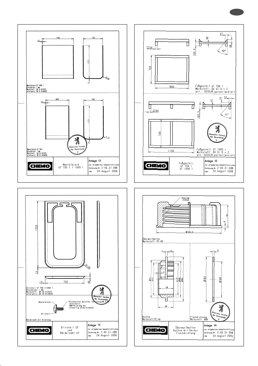
D
5
Page 6
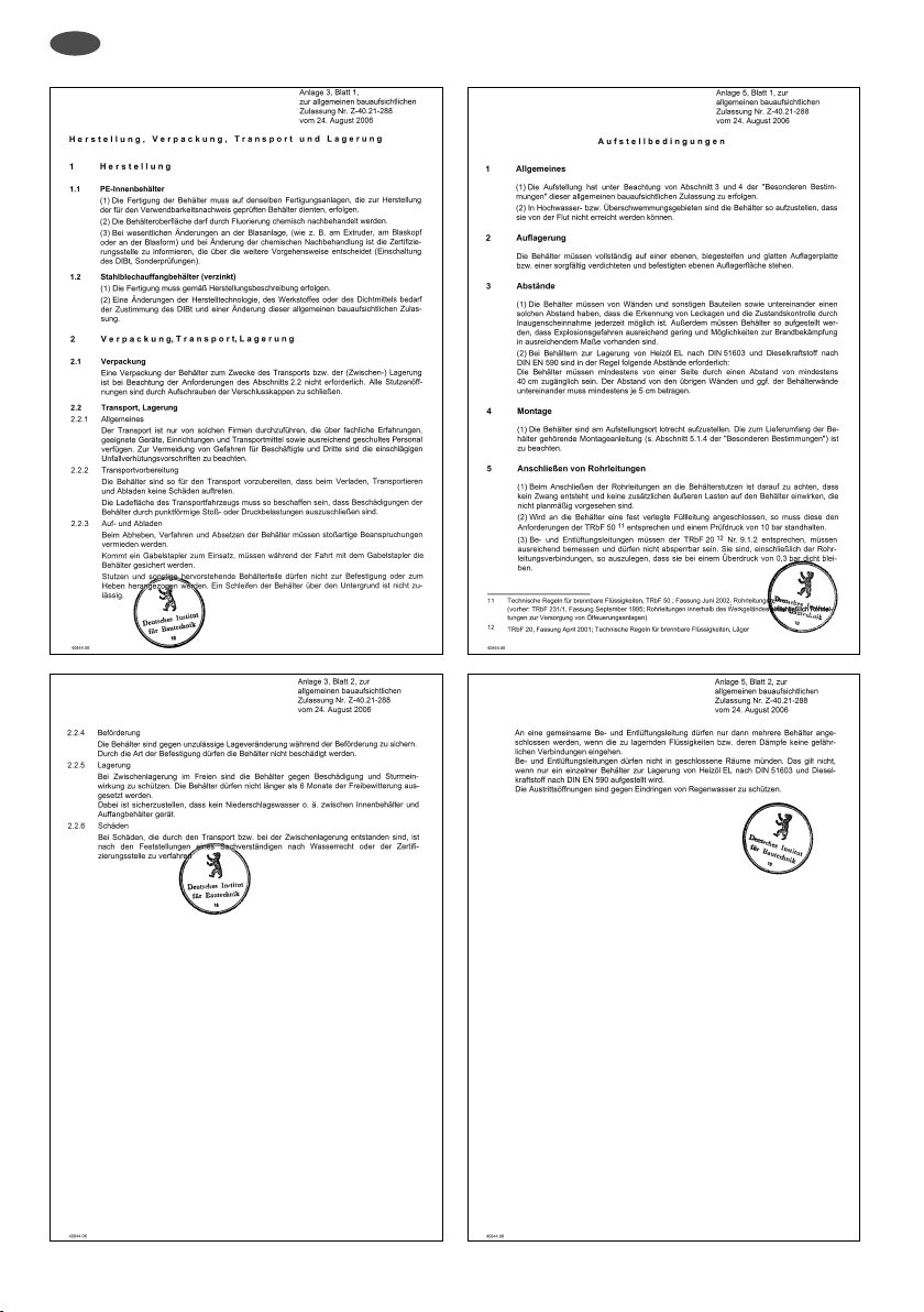
D
6
Page 7
D
2. Transport-, Montage- und Betriebsanleitung
Diese Anleitung gilt für CEMO UNI-/MULTI-Tank
gemäßallgemeinerbauau fsichtlicher ZulassungZ-40.21-288.
Die CEMO UNI-/MULTI-Tanks werden als Einheit mit
einer durch eine Schrumpfhaube gehaltenen stoßfesten
Abdeckung aus wiederverwertbarem Material als Transportschutz ausgeliefert. In der Abdeckung ist auf der
Tankseiteder Füllstandsanzeigeruntergebracht.
Die Tanks sind werkseitig mit eingebauter Leckagesonde
ausgestattet. Das Fußgestell ist werkseitig schon fest
montiert. Der Deckel ist erst am Aufstellort zu entfernen!
In einem Tankstutzen beœnden sich in einer Hülle di e Zulassung mit Transport-, Montage- und Betriebsanleitung,
Überwachungserklärungund Garantieurkunde.
Die Tanks dürfen nur in allseitig geschlossenen Räumen
aufgestellt werden.
Ein zusätzlicher Auffangraum ist nicht erforderlich!
VonFeuerungsanlagen (Feuerstellen, Schornsteine,
Verbindungsstücke) muss ein Abstand
von mindestens 1 m eingehalten werden.
Die Tanks dürfen nicht
a) in Durchgängen und Durchfahrten,
b) in Tr eppenräumen,
c) in allgemein zugänglichen Fluren,
d) auf Dächern von Wohnhäusern, Krankenhäusern,
Bürohäusern und ähnlichen Gebäuden sowie in
derenDachräumen,
e) in Büroräumen,
f) in Gast- und Schankräumen
aufgestellt werden.
Die Befüllung der Tanks mit Heizöl oder Dieselkraftstoff
darf nur im freien Einlauf ohne festen Anschluss der
Befüllleitung erfolgen.
In einen der oberen Stutzen ist der Füllstandsanzeiger
einzuführen. Die Verschlusskappe wird zuvor entfernt, di e
Überwurfmuttern von unter über den Anzeiger gesteckt
und die Gewindebuchsen aufgeschraubt. Danach wird der
Füllstandsanzeiger in der Ar t befestigt, dass di e Überwurfmutter auf den Stutzen unter Verwendung der mitgelieferten Dichtung geschraubt wird.
Die Tanks können auch mit einem festen Anschluss zur
automatischen Entnahme mittels Tauchpumpen bzw.
Pumpen mit nachfolgendem Druckspeicher angeschlossen werden. Die Anlagen sind dann mit einer Sicherheitsautomatik zu versehen, die eine Heberwirkung
ausschließt.
Bei automatischer Entnahme ist für eine ausreichende
Belüftung der Tanks zu sorgen, z.B. durch Einsatz eines
Be- und Entlüftungspilzes (2 “), der in die vorhandene
Gewindebuchse eingesetzt werden kann.
Für die Lagerung nicht brennbarer Medien und den dafür
vorgeschriebenen Anschluss einer festen Füllleitung gibt
es als Zubehör die Überfüllsicherung mit der Best.-Nr.
7330. Für die Lagerung von gebrauchten Schmier-,
Hydraulik- oder Wärmeträgerölen gibt es als Zubehör die
Leckagesonde mit der Best.-Nr. 7391.
3. Überwachungserklärung
Überwachungserklärung
für CEMO UNI-Tank / MULT I-Tank
aus Polyethylen hoher Dichte und verzinktem Stahlblech für die drucklose Lagerung von Medien entsprechend der allgemeinen bauaufsichtlichen Zulassung
Z-40.21-288.
Artikel-Nr.: 7379/7380/7381/7382
Behälterinhalt: 750/1000 l
Prüfdruck: 0.3 bar
Zulassungsnummer: Z-40.21-288
Wir bescheinigen, dass der Behälter den Fest legungender allgemeinenbauaufsichtlichen Zulassung
entspricht. Die Druck- und Dichtheitsprüfung wurde
durchgeführt.
DieWerksachkundigen:
CHEMOWERKGmbH
7
Page 8
GB
CEMO UNI-/MULTI-Tank 750 l/1000 l
Tank documents and technical information,
Approval No.: Z- 40.21-288
1. Approval ”OPERATOR EXCERPT” page 8-13
2. Tr ansport, installation and
operating instructions page14
3. Insp ection declaration page 14
Important documents for the op erator!
Please keep in a safe place!
(Documents are to be presented during inspections
of the tank system.)
1. Approval ”OPERATOR EXCERPT”
This is a translation of the German original document
and has not been reviewed by the German Institute for
Structural Engineering.
DEUTSCHES INSTITUT FÜR BAUTECHNIK
(German Institute for Structural En gine ering)
An institution of public law
10829 Berlin, August 24, 2006
Kolonnenstraße 30 L
Tel (0 30) 7 87 30 - 345
Fax 030 78730 -416
Ref.: I 55 -1.40. 21-40/06
General Construction Inspection Approval
Approval number:Z-40.21-288
Applicant: Chemowerk GmbH
Subject of approval: Blown polyethylene (PE-HD) containers
Valid until: May 31, 2011
The subject of approval listed above is hereby granted general
construction approval.*
This General Construction Inspection Approval consists of eight pages
and œve annexes with 15 pages.
* This General Construction Inspection Approval replaces the General
Construction Inspection Approval no. Z-40.21-288 dated May 28, 2001
In den Backenländern
71384Weinstadt
with integrated sheet steel collection tray
750 l and 1000 l
Type HT 750/1000
e
th
of
al
Se
itut
st
In
an
Germ
for
En
ct
ru
St
gineering
al
ur
e
Page 2 of the General Construction Inspection Approval no. Z-40.21-288,
August 24, 2006
I. GENERAL REGULATIONS
1 The General Construction Inspection Approval certiœes that the ap-
proved object is suitable and useful in the sense of the construction
regulations of the German states.
2 The General Construction Inspection Approval does not replace
the permits, permissions, and certiœcations legally required for a
construction project.
3 The General Construction Inspection Approval is granted without
affecting the rights of third parties, in particular private proprietary
rights.
4 Manufacturers and sellers of the approved object must make copies
of the General Construction Inspection Approval, available to us ers
of the approved object and point out that the General Construction Inspection Approval must be present at the plac e the object
is used. This provision does not affect the further regulations in
the ”Particular Regulations”. If requested, copies of the General
Construction Inspection Approval must be made available to the
involved authorities.
5 The General Construction Inspection Approval may be reproduced
only in whole. Publication of excerpts requires permission from the
German Institute for Structural Engineering. Te xt and drawings in
advertising must notcontradict theGeneral Construction Inspection
Approval. Translations of the General Construction Inspection
Approval must contain the notice: ”This is a translation of the German original document and has not been reviewed by the German
Institute for Structural Engineering”.
6 The General Construction Inspection Approval, is granted subject
to revocation. The regulations of the General Construction Inspection Approval are subject to subsequent additions and changes,
especially when new technical knowledge necessitates them.
e
th
of
Seal
Germ
fo
En
r
an
St
gine
e
stitut
In
al
ur
ct
ru
ing
er
8
Page 9

GB
Page 3 of the General Construction Inspection Approval no. Z-40.21-288,
August 24, 2006
II. PARTICUL AR REGULATIONS
1Object of approval and area of application
(1) Object of this General Construction Inspection Approval is
factory-produced containers described in Annex 1, consisting
of a polyethylene (PE-HD) interior container produced in a
blow moulding process and an external container made of
galvanised sheet steel. The containers are manufac tured with
volume capacities of 750 I and 1000 I.
On the top of the container s there are four connection muffs
to accept equipment for œlling, aeration and deaeration, emptying, and œll level monitoring. The volume between the inner
and outer container s is equipped with a leak detector.
(2) The containers may only be placed as single containers within
buildings, and not in Zone 0 and 1 areas with risk of explosion.
(3) The container s can be utilised for storage at normal pressure
of the following liquids:
1. Heating oil EL grade, as in DIN 51 6031
2. Diesel fuel as in DIN 5902
3. Diesel fuel as in DIN EN 14214 (biodiesel)
(permitted only in inner containers marked as „CPA“)
4. Lubricating oils, hydraulic oils, heat transfer oils (Q grade)
mixed or unmixed, with ›ash points > 55 °C
5. Used lubric ating oils, hydraulic oils, thermal oils Q grade,
used oils, ignition point over 55 °C (operator must be able
to prove origin and ignition point)
6. Photographic chemic als (new and used), commercial
grade, in usable concentrations, with a density of no more
than 1. 15 g/ml
7. Plant oils such as cottonseed, olive, canola, castor, or
wheat germ oil in all concentrations
(4) This General Construction Inspection Approval satisœes
the obligation to obtain a suitability determination for water
regulations and the qualiœcation approval under § 19 h of the
Water Resources Act.
2Bestimmungen für die Bauprodukte
2.1Eigenschaften und Zusammensetzung
2.1.1Materials
The moulding compounds and materials given in Annex 2 may be
used for the manufacture of the containers.
2.1.2Construction drawings
Construction details of the containers must conform to Annexes
1.1 through 1.6.
1 DIN 51 603-1DIN 51603-1 September 2003, ”Liquid Fuels, Heating Oils,
2 DIN EN 59 0March 2004, ”Fuels for Ve hicles, Diesel Fuel, Minimum
3 DIN EN 14214November 2003; Automotive fuels - Fatty acid methyl
Part 1: Heating Oils EL Minimum Requirements”
Requirements and Testing Procedures”, German version
EN 590: 2004
esters (FAME) for diesel engines - Re quirem ents and test
methods; German version EN 14214: 20 03
Se
Germ
for
En
al
an
St
gine
e
th
of
e
itut
Inst
al
ur
ct
ru
ing
er
Page 4 of the General Construction Inspection Approval no. Z-40.21-288,
August 24, 2006
2.1.3Stability veriœcation
The containers are stable under prescribed conditions of use up
to an operating temperature of 30 °C.
2.1.4Fire behaviour (›ame resistance)
Containers complying with this General Construc tion Inspection
Approval, consisting of interior and exterior containers, are
designed to withstand ›ames in rooms of buildings that meet
the requirements for heating and storage rooms for 30 minutes
without leaking.
2.1.5Leak detection
To satisfy the water directive requirements, a leak detector suit-
able for the intended use, with General Construction Inspection
Approval, must be installed between the interior and exterior
containers [see Secs. 1 (1) and 5.1.1 (3)].
2.2Manufacture, packaging, transport, storage and labelling
2.2.1Manufacture
(1) The container must be manufactured according to the manu-
facturing description œled with the DIBt.
(2)Inaddition to themanufacturing description,the requirements
of Annex 3, Sec. 1 must be followed.
(3) The container s are may be manufactured only in Plant 3 of
Chemowerk GmbH.
(4)
To reduce permeation, the inner containers may be ›uorinated.
2.2.2Packaging, transport, storage
Packaging, transport, an d storage must confor m to Annex 3, Sec.2.
2.2.3Labelling
(1) The containers must be labelled with the conformity mark
in compliance with the conformity directives of the German
states. The mar k may be used only if the requirements of
Sec. 2.3 are fulœlled.
(2) In addition, the manufacturer must label the container s on the
outside wall with the following, clearly visible and durable:
- Manufacturing number;
- Date of manufacture;
- Volume capacity of the interior container in litres, up to
allowed œlling (compliant with Approval Guidelines for Avoidance of Overœlling „ZG-ÜS“)
- Material (the labelling must indicate the moulding compound
used, for example, „PE-HD – Lupolen 4261 AG UV“) for
interior and exterior containers.
6
;
- Allowed operating temperature;
- The ›uorinated inner container labelling must indicate the
material and also include the letters “CPA”.
- A notice that operation is at normal pressure;
- A notice ”Outdoor placement not allowed”;
- A notice ”Only for storing substances according to General
Construction Inspection Approval no. Z-40.21-288”.
(3) The œlling level corresponding to the maximum
approved œlling vo lum e (see Sec. 5.1.3)
must be marked on the level indicator.
Burn te st approved by the German Commission on Flammable Liquids (DAbF).
4
5Name and company address/location are on record with the DIBt (Ger-
man Institute for Structural Engineering).
Approval Guidelines for Avoidance of Overœlling (ZG-ÜS), May 1993, in the
6
DIBt (German Institute for Structural Engineering) publication ”Approval
Guidelines fo r Container and Pipeline Safety Features”, January 1996
Seal
German
St
for
En
of
ruct
gine
In
e
th
stitut
ur
ering
al
e
9
Page 10

GB
Page 5 of the General Construction Inspection Approval no. Z-40.21-288,
August 24, 2006
2.3Proof of conformity
2.3.1Overview
(1) Proof that the containers conform to the conditions of this
General Construction Inspection Approval is a certiœcate of
conformity obtained by the manufacturing plant on the basis
of the manufacturer‘s production quality control and regular
external monitoring, including a œrst test of the containers to
the standards of the following conditions.
(2) For a certiœcate of conformity to be granted and the external
monitoring including therequiredproduct test,the manufacturer
of the containers must use the services of a certiœcation agency
and a monitoring agency recognised fo r these purposes.
(3) The certiœcation agency must give a copy of the conformity
certiœcate to the DIBt.
A copy of the œrst test report must also be given to the DIBt .
2.3.2. Manufacturer‘s in-house production control
(1)
The manufacturer must set up and carry out in-house production control in every production plant. Manufacturer‘s in-house
production control means here the required continual monitoring of production which assures that the containers or the type
”JW 3” leak detectors manufactured there comply with the
conditions of this General Construction Inspection Approval.
Manufacturer‘s in-house production control means the required continual monitoring of production which assures that
the containers manufactured there comply with the conditions
of this General Construction Inspection Approval.
(2) The in-house production control should include at least the
tests listed in Annex 4, Sec.1.
(3)
The results of the in-house production control must be recorded
and analysed. The records must contain at least the following
data:
- Designation of the product produced or the star ting material
- Type of control or test
- Date of manufacture and of testing of the product or the
starting material, or its constituent components
- Results of the controls and tests and comparison with the
requirements
- Signature of the person in charge of the in-house production
control.
The data logs are to be kept at least œve years and must be communicated to the external monitoring agent. On request they
are to be shown to the DIBt and the competent highest building
supervisoryagency.
For unsatisfactory test result s, the manufacturer must immediately take the necessary steps to remedy the defect. Products
that do not meet speciœcations must be handled so that they
cannot be confused with compliant products. After the defect is
remedied, the failed test must be repeated as soon as technically
possible.
2.3.3External monitoring
(1) In the manufacturing plant, the in-house production control is
to be externally monitored as in Annex 4, Sec.2 (2) at regular
intervals, at least twice per year.
(2) As part of the external monitoring, a œrst test of the contain-
ers as in Annex 4, Sec. 2 (1), s to be performed. In addition,
samples for random testing can be taken. The sample taking
and tests are the responsibility of the recognised monitoring
agency. If the suitability tests that the General Construction
Inspection Approval is based on were
carried out on samples ofœcially taken
from production runs, then these tests
replace the œrst test.
Seal of
Germ
for St
an
ru
Engine
the
e
itut
st
In
al
ur
ct
ing
er
10
Page 6 of the General Construction Inspection Approval no. Z-40.21-288,
August 24, 2006
(3) The results of the certiœcation and external monitoring are to
be kept for at least œve years. The certiœcation agency or the
monitoring agency must present them to the DIBt in any case,
and on request to the competent highest building supervisory
agency.
3Conditions for design and measurement
(1) For behaviour withstanding ›ames, see Sec. 2.1.4.
(2) The conditions for installing the containers are found in the
water, work safety, and construction directives.
In addition the requirements of Annex 5 apply.
(3) The container s must be protected against impact by vehicles,
for example by installing in protected places, use of collision
guards, or installing in a suitable collecting area.
4Conditions for implementation
(1) Installation of the containers is subjec t to Annex 5.
(2) Installation and placement of the containers must be carried
out by only those businesses which are specialists for this
work in the meaning of § 19 I Water Resources Ac t, unless
these tasks are excepted from requiring specialist companies
in state regulations.
(3) The installing company must certify that installation was
proper, obser ving the manufacturer‘s instructions (see Sec.
5.1.4) and those in Annex 5.
(4) Containers damaged in transport or installation may not be
used if the damage compromises the leak tightness or the
mechanical stability of the containers.
(5) Repairs to the internal container are not allowed.
(6) Assessment of damages and steps to remedy damages
should be made in consultation with an expert in water direc-
tives or the certiœcation agency.
Conditions for use, maintenance, servicing, und testing
5
5.1Use
5.1.1Equipping the containers
(1) The conditions for equipping the containers are found in the
water, construction, and work safety directives. If there are
no water or construction directives for equipping containers
to store non-combustible liquids, Sec. 9 of the Technical
Regulations for Combustible Liquids (TRbF) 20
followed.
(2) Accessories must be designed to avoid unacceptable high or
negative pressures and unacceptable loads on the container
wall.
(3) The container s will be equipped with a leak detector of type
“LS-3” with the General Construction Inspection Approval
no. Z-65.40-256. (Basic equipment for EL grade heating oil
according to DIN 51603 and diesel fuel according to DIN EN
590.) The containers may also be equipped with another
leak detector suited for the intended use if it has General
Construction Inspection Approval. Beside the leak detector,
see Sec. 2.1.5, every container must be equipped with a level
indicator.
7Technical Re gulations for Combustible Liquids, TRbF 20 April 2001 ver-
sion of „Storage“
Seal
German
for
En
7
should be
th
of
In
ruct
St
er
gine
e
stitut
ur
ing
e
al
Page 11

GB
Page 7 of the General Construction Inspection Approval no. Z-40.21-288,
August 24, 2006
5.1.2Storedliquids
(1) It is not permitted to store the liquids listed in Sec. 1 (3) if they
are mixed with one another or with other substances, or if a
different liqui d has already been stored in the container.
(2) It is not permitted to store contaminated liquids if the con-
taminants would lead to altered material behaviour.
(3) The plant oils listed in Sec. 1 (3 ) under item 7 require ad-
ditional documentation that the container material complies
with food regulations before being used as food or in food
production.
(4) The diesel fuel meeting DIN EN 14214 standards (biodiesel)
listed in Sec. 1 (3) under item 7 may be stored only in containers designated as ›uorinated [see Sec. 2.2.3. (2)].
(5) To use the containers to store photographi c chemicals (see
Sec. 1 (3) under item 6), an additional protective coat as per
Annex 4, Sec.1.4, must be applied to the metal parts.
5.1.3Usable container volumes
The allowed container œlling volume does not exceed 95 %, un-
less a different œlling volume is proven acceptable or is required,
referring to TRbF 20 Nr. 9.3.2.2. If there is a safety device
for avoiding overœlling, it must be set to the acceptable value.
5.1.4Documentation
The container manufacturer must supply the following docu-
ments to the operator:
- A copy of this General Construction Inspection Approval or an
approved excerpt of it;
- A copy of the General Construction Inspection Approval for
the leak detector as in Sec. 1 (1) and also Sec. 5.1.1 (3), if the
container is delive re d with one installed;
- A copy of the General Construction Inspection Approval for the
overœlling safety device
if the container is delivered with one installed;
- Installation instruc tions for setting up the containers
5.1.5Operation
5.1.5.1General instructions
(1) Before the individual free-standing containers are taken into
operation, the operator must afœx a plate at a suitable place,
identifying the stored liquid and st at ing its density and its
concentration.
The labelling requirements of other di rectives are not af fe cted
by this and must also be satisœed.
(2) The operating directives of TRbF 20 and the Ordinance for
Facilities and Companies Handling Substances Hazardous to
Water (VAwS) apply.
5.1.5.2Filling and empt ying
(1)
Before œlling, check whether the liquid to be stored is approved, matches the designation of the container, and is at a
temperature allowed in Sec. 5.1.5.3. In addition, check how
much liquid can be stored in the container and whether the
overœll safety device/limit indicator is in good operating condition.
(2) Filling an d emptying requires a œxed, stably installed line
(pipe or hose) unless the water and work safety directives
allow an exception.
(3) Containers for storing heating oil complying with DIN 51 603
and diesel fuel complying with DIN EN 590 are not subject
to the requirements of Sec. (2) and may be œlled from a tank
vehicle or por table tank with a full hose system using an
insertable automatic cut-off fuel pump
nozzle, at œlling rates of up to 200 I/min.
(4) Filling must be completely supervised.
Seal of
Germ
for
an Inst
ruct
St
Engine
the
er
itut
al
ur
ing
Page 8 of the General Construction Inspection Approval no. Z-40.21-288,
August 24, 2006
5.1.5.3Further conditions
(1) The operating temperature of the stored liquid must not
exceed 30° C. However, for short times, temperatures of 10
K above the operating temperature (such as high er temperature of the storage liquid when œlling) are excepted.
(2) When storing used lubricating, hydraulic and heat transfer
oils and used photographic chemicals, the container is used
as a collection container, with a connector for securely connecting a permanent pipeline or a removable line for use by
trained technicians only.
5.2Maintenanceand servicing
The operator of a storage facility is obliged to employ for main-
(1)
tenance
and cleaning of the containers only those businesses
which are specialists for this wo rk in the meaning of § 19 I of
the Water Re sourc es Act
by state regulations from requiring specialist companies.
(2) Deviating from (1), maintenance tasks may also be carried
outbythe container manufacturer‘s owntechnicalpersonnel.
(3)
When ›ammable liquids are stored, the tasks described in
(1)
must be carried out by companies that are considered
qualiœed specialists according to TRbF 20 No. 15.4.
(4) Steps to remedy damages should be decided in consultation
with an expert in water directives or the certiœcation agency.
(5) Cleaning the inside of containers with solvents, for example,
for an inspection, is not allowed. The accident prevention
directives and directives for use of chemical cleaning agents
and the disposal of cleaning waste must be observed.
5.3Tests
5.3.1Per formance test / test before commissioning
(1) After installing the container and mounting the pipelines and
safety devices, a per formance test is necessary. It consists
of visual examination, a leak te st, testing the pipelines,
œttings and other equipment.
(2) A performance test does not replace a necessary test
before commissioning by a specialist for water directives;
however, the two can be performed together.
5.3.2Ongoing tests / tests after commissioning
(1) The operator must examine the contain ers visually for
leakage at least once per week. As soon as leakage is
discovered, the unit must be taken out of operation and the
damaged container emptied.
(2) The leak detector (complying with Sec. 1 (1) or Section
5.1.1 (3)) is to be checked for proper operation as speciœed
in the General Construction Inspection Approval for that
leak detector.
(3) Tests as required by other directives are not affected by this
and must also be satisœed.
Leichsenring
e
8 Water Resources Act (Wasserhaushaltsgesetz – WHG),
dated August 19, 2006
8
, unless these tasks are excepted
Seal of
German
St
for
En
ruct
gine
In
e
th
stitut
ur
ering
e
al
11
Page 12

GB
of the General Construction Inspection
Manufacture
1Manufacturing requirements
1.1PE inner container
(1) The containers must be manufactured in the same manufac-
turing facilities where the containers tested for the proof of
suitability were produc ed.
(2) It is permissible to ›uorinate the container surface.
(3) If the blowing apparatus is changed (the extruder, blow ing
head, or blowing mould, for example) the certiœcation agency
is to be informed. They will then make a decision about how
to proceed (involving the DIBt, spec ial tests).
1.2Sheet steel bund (galvanized)
(1) The container must be manufactured according to the manu-
facturingdescription.
(2) Any change in manufacturing technology, material. or
sealant requires DIBt approval and changes to this General
Construction Inspection Approval.
2Packaging, transport, storage
2.1Packaging
Packaging the containers for the purpose of transport or (tem porary) storage is not necessary if the requirements of Sec. 2.2
are met. The openings of all connection muffs must be closed by
screwing on their caps.
2.2Transport,storage
2.2.1General instructions
Transpor t must be carried out by only those companies with
specialist experience, suitable machinery, equipment, and
means of transpor t, and sufœciently trained personnel. To avoid
hazards for employees and third parties, the applicable accident
prevention directives must be observed.
2.2.2Transportpreparation
The containers must be prepared for transport so that no dam-
age occurs during loading, transport, and unloading.
The loading sur face of the transport vehicle must be constructed
so that it is not possible to damage the containers by impact or
pressure against a pointed object.
2.2.3Loading and unloading
When lifting, moving, and setting down the containers, impact
loads must be avoided.
If a fork lift truck is used, the containers must be secured during
the moving with the fork lift.
Connection pieces and protruding parts of the containers may
not be used as lifting points for the containers. The containers
may not be dragged across a ›oor or the ground.
Annex 3, Sheet 1
Approval no. Z-40.21-288,
Se
Germ
for
En
August 24, 2006
e
th
of
al
e
itut
st
In
an
al
ur
ct
Stru
ing
er
gine
of the General Construction Inspection
2.2.4 Carriage
The containers must be secured against unacceptable shifts of
position during carriage.
The mode of fastening may not cause the containers to be
damaged.
2.2.5Storage
When temporarily placed outside, the containers should be
protected against damage and storms. Containers must not be
exposed to we at her ing for more than six months.
2.2.6Damag e
When damages occur during transport or storage, the œndings
of a water directives expert or the certiœcation agency should be
followed.
Annex 3, Sheet 2
Approval no. Z-40.21-288,
Se
Germ
r
fo
En
August 24, 2006
e
th
of
al
e
stitut
In
an
al
ur
ct
ru
St
ing
er
gine
12
Page 13

GB
of the General Construction Inspection
Approval no. Z-40.21-288,
Installation conditions
1 General
(1) The container installation must follow Secs. 3 and 4 of the
Particular Regulations of this General Construction Inspection Approval.
(2) In high water or ›ooding areas, the containers must be
placed so that they cannot be reached by high water.
2 Bearing surface
The containers must be placed completely on a ›at, hard
(unbending) smooth support slab or a carefully compacted and
hardened support surface.
3 Distances
(1) The containers must be at a distance from walls, ot her
construction, and each other that leakage may at any time be
detected by visual inspection. The container s must
be placed so that risk of explosion is sufœciently small and
means to extinguish œre are sufœciently available.
(2) For containers used to store EL grade heating oil according
to DIN 51603 and diesel fuel according to DIN EN 590, the
following clearances are normally required:
The containers must have an access clearance of at least
40 cm on at least one side.
The distance to the other walls and between adjacent
containers must be at least 5 cm.
4 Setting up
The containers must be installed level and plumb at their location. The installation instructions delivered with the containers
(see Sec. 5.1.4) must be followed.
Annex 5, Sheet 1
August 24, 2006
of the General Construction Inspection
Lines for aerat ion and deaeration must not discharge into
closed spaces.
This does not apply when only a single container for storing
heating oil ac cording to DIN 51603 or diesel fuel according to
DIN EN 590 is installed.
Annex 5, Sheet 2
Approval no. Z-40.21-288,
August 24, 2006
The outlet openings must be protected from rainwater.
e
th
of
al
Se
Germ
fo
En
r
an
St
gine
e
stitut
In
al
ur
ct
ru
ing
er
5 Connecting pipelines
(1) When connecting pipelines to the container connection
muffs, give at tent ion that nothing is forced and that no
additional external loads that are not designed to act on the
containers are generate d.
(2) If a permanently laid pipeline is connected to the container, it
must satisfy the requirements of TRbF 50
test pressure of 10 bar.
(3) Pipelines for introducing and releasing air must conform to
11 Technical Regulations for Combustible Liquids, TRbF 50, June 2002 ver-
sion; Rohr leitungen („Pipelines“) (replaces TRbF 231/1, September 1995
version; ”Pipelines on Factory Premises including Pipelines Supplying
Oil Firing Systems”
12 TRbF 20, April 20 01 version; Technische Regeln für brennbare Flüs-
sigkeiten, Läger (“Technical Regulations for Combustible Li quids,
Storage Ro oms” )
12
TRbF 20
Nr. 9.1.2, be of adequate dimensions, and may not
have a cut- off possibility.
They and their pipeline connections must be set up so that
they remain leak proof at 0. 3 bar overpressure.
11
and withstand a
of
al
Se
Inst
an
Germ
ct
ru
St
for
gine
En
e
th
e
itut
al
ur
ing
er
13
Page 14
GB
2. Transpor t, installation
and operating instructions
These instructions apply for the CEMO UNI-/MULTI-Tank
750 l / 1000 l in accordance with the general construc tion
inspection approval Z-40.21-288.
The CEMO UNI-/MULTI -Tanks are supplied as a unit with
an impact-proof cover of recyclable material held in plac e
by a shrink-wrap as protection during transportation. The
level indicator can be found in the cover on the tank side.
The tanks are œtted with a leak sensor in the works.
The base is already œtted in the works. The cover should
only be removed at the place of installation!
The approval certiœcate with transport, installation and
operating instructions, inspection declaration and warranty document can be found in an envelope in a tank
connectionpiec e.
The tanks may only be installed in a fully enclosed room.
An additional collecting room is not required!
The tank must be installed at least 1 m from any furnaces
(œreplaces, chimneys, connecting pieces).
The tanks may not be installed in
a) passages,
b) staircases,
c) generally accessible corridors,
d) on the roofs of residential buildings, hospitals, ofœce
buildings and similar buildings or in their attics,
e) ofœces,
f) in guest rooms and bars.
The tanks may only be œlled with heating oil or diesel fuel
using a free inlet without a œxed connection of the œlling line.
Insert the level indicator in the upper connection piec e.
The cap has to be removed beforehand, slide the union
nut over the indicator from below and screw the threaded
liner into place. Then fasten the level indicator by screwing the union nut onto the connection piece using the
enclosed seal.
The tanks can also be connected with a œxed connection
for automatic removal via submerged-pumpsor pumps
with subsequent accumulator. In this case the systems
should be œtted with an automatic safety device to prevent
a siphon effect.
If operated with an automatic removal the tanks must be
adequately ventilated, e.g. through the use of an aeration
and ventilation insert (2”) that can be mounted in the existingthreadedliner.
The overœll safety device with the order no. 7330 is available as an accessory for stor ing non-›ammable media
and the speciœed connection.
The leak sensor with the order no. 7391 is available as
an accessory for storing used lubricating, hydraulic or
thermal oils.
3. Inspection declaration
Inspection declaration
for CEMO UNI-Tank / MULT I-Tank
of high-density polyethylene and galvanised sheet
steel for the unpressurised storage of media
according to the general construction inspection
approval Z-40.21-288.
Article No.: 7379/7380/7381/7382
Tank content: 750/1000 l
Test pressure: 0.3 bar
Approval number: Z-40.21-288
We conœrm that the tank complies with the provisions
of the general construction inspection approval. The
construction and leak tests have been performed.
The Works Experts:
14
CHEMOWERKGmbH
Page 15
F
UNI-/MULTI-citerne
CEMO 750 l/1000 l
Documents de ci terne et informations techniques, N° d‘homologation: Z- 40.21-288
Documents importants pour l‘exploitant !
A conserver soigneusement !
(Les documents doivent être présentés lors de
contrôles des équipements de la citerne.)
1. Notice de montage, d‘utilisation et de transport
Cette notice s‘applique aux citernes CEMO – UNI- et MULTIciterne 750 l / 10 00 l – conformément au document d‘homolo gation
générale en matière de construction et de génie civil.
Les UNI-citerne et MULTI-citerne CEMO sont livrées
sous forme d‘une unité avec un cache résistant aux chocs
maintenu par une housse en matériau recyclable qui est
employée comme protection de transport. L‘ indicateur de
niveau est monté côté citerne dans le cache. Les citernes
sont équipées au départ d‘usine avec une sonde anti-fuites. La palette -socle est déjà montée et œxée en usine. Le
couvercle ne doit être retiré que sur le site d‘installation !
Les documents d‘homologation avec la notice de
montage, d‘utilisation et de transport, la déclaration de
contrôle et le certiœcat de garantie sont entreposés dans
un sachet dans une des tubulures de la citerne.
Les citernes ne peuvent être installées que dans des
locaux fermés de tous côtés.
Attention: rétention intégrée - aucun bac de rétention
supplémentaire nécessaire !
L‘indicateur de niveau doit être introduit dans une des
tubulures supérieures. Le capuchon de fermeture est tout
d‘abord retiré, l‘écrou-raccord est positionné sur l‘indicateur par le bas et les douilles taraudées sont vissées.
L‘indicateur de niveau est ensuite œxé de telle manière qu e
l‘écrou-raccord est vissé sur la tubulure en utilisant le joint
d‘étanchéité livré.
Les citernes peuvent être également équipées d’un raccordement œxe pour soutirage automatique au moyen de
pompes submersibles ou de pompes avec accumulateur
hydraulique placé en aval. Les installations doivent être
alors équipées d‘un système automatique de sécurité aœn
d‘exclure un effet de siphon.
Dans le cas d‘un soutirage automatique, il est impératif de
veiller à une ventilation sufœsante des citernes, par exemple en utilisant un champignon de purge d‘air / de ventilation (2“), qui peut être monté dans la douille taraudée
existante (le dispositif doit garantir le maintien permanent
de la pression atmosphérique à l’intérieur du réservoir).
Le témoin de fuites est à disposition comme accessoire
pour le stockage d‘huiles lubriœantes, hydrauliques et
caloporteuses usées.
2. Déclaration de contrôle
Déclaration de contrôle
pour UNI-citerne / MULT I-citerne CE MO
en polyéthylène haute densité et tôle d‘acier galvanisé
pour le stockage sans pression de ›uides conformément à l‘homologation générale en matière de construction et de génie civil Z-40.21-288.
Il est impératif de respecter une distance de sécurité d‘au
moins 1 m par rapport aux installations de chauffage
(foyers, cheminées, pièces de raccordement).
Il est interdit d‘installer les citernes
a) dans des couloirs ou des allées de passage,
b) dans des cages d‘escaliers,
c) dans des couloirs accessibles à tous,
d) sur des toits de mai sons d‘habit at ion, d‘hôpitaux,
de bâtiments abritant des bureaux et de bâtiments
similaires ainsi que dans leurs combles,
e) dans des bureaux,
f) dans des hôtels et des auberges
Le remplissage des citernes avec du fuel ou du carburant
diesel n‘est autorisé qu‘avec une tête d‘entrée libre sans
raccordement œxe du tuyau de remplissage.
Référence: 7379/7380/7381/7382
Contenance citerne: 750/1000 l
Pression de contrôle: 0.3 bar
Numéro d’homologation: Z-40.21-288
Par la présente, nous certiœons que le conteneur satisfait aux dispositions mentionnées dans l‘homologation
générale en matière de construction et de génie civil.
Le contrôle de pression et d‘étanchéité a été réalisé.
Les experts en usine:
CHEMOWERKGmbH
15
Page 16
I
CEMO Serbatoio
UNI / MULTI 750 l/1000 l
Documentazioni serbatoio ed informa zioni
tecniche, N. omologazione: Z- 40.21-288
Documentazioni importanti per il proprietario!
Si prega di conservare accurat amente!
(Le documentazioni devono essere mostrate in caso
di controlli dell’impianto di rifornimento.)
1. Istruzioni di trasporto, montaggio ed uso
Questa istruzione è valida per serbatoio CEMO UNI-/MULTI 750
l / 1000 l se condo l’omologazione generaledicontrollo della
costruzione Z-40.21-288.
I serbatoi CEMO UNI-/MULTI sono forniti come unità con
una copertura antiurto retta da una calotta di contrazione
realizzata in materiale riutilizzabile come protezione di trasporto. Nella copertura è collocato sul lato del serbato io
l’indicatore del livello di riempimento. I serbatoi sono
dotati da fabbrica con un sensore rilevatore di perdite. La
base è montata in fabbrica già in modo œsso. Il coperchio
deve essere smontato soltanto sul luogo di montaggio!
In una rientranza del serbatoio si trovano in una custodia
l’omologazione con le istruzioni di trasporto, montaggio
uso, dichiarazione di monitoraggio e certiœcato di garanzia.
I serbatoi possono essere montati soltanto in ambienti chiusi.
Non è necessario un vano di raccolta supplementare!
È necessario tenere una distanza minima di 1 m da fonti
di calore (focolai, camini, elementi di collegamento).
I serbatoi non possono essere inst allati
a) in passaggi o transiti,
b) in vani scala,
c) in corridoi generalmente accessibili,
d) su tetti di abitazioni, ospedali, ufœci e simili ediœci,
nonché nei loro sofœtti,
e) ufœci,
f) in ambienti per ospiti e ripostigli
Il riempimento dei serbatoi con gasolio per riscaldamento
o carburante diesel, può essere eseguito soltanto con
af›usso libero senza collegamento œsso della condotta di
riempimento.
In una delle rientranze in alto è collocato l’indicatore di li vello. Il coperchio di chiusura viene prima rimosso, il dado
e
a risvolto inserito da sotto sul visualizzatore ed avvitate
le boccole œlettate. Successivamente viene œssato l’indicatore di livello in modo tale che il dado a risvolto venga
avvitato sui sostegni utiliz zando la guar nizi one compresa
nella fornitura.
I serbatoi possono essere collegati anche con un
collegamento œsso per il prelievo automatico con delle
pompe-sommerse o pompe con seguente accumulatore.
Gli impianti devono quindi essere dotati di un automatismo
di sicurezza che esclude un effetto di sollevamento.
In caso di prelievo automatico è necessario provvedere ad
una sufœciente aerazione dei serbatoi, ad es. utilizzando
un tasto a fungo per l’aerazione e lo sœato (2”) il quale può
essere impiegato nella boccola œlettata presente.
Per lo stoccaggio di sostanze non inœammabili ed il collegamento di una condotta di riempimento œssa preposta, è
disponibile come accessorio il dispositivo di eccessivo
riempimento con il N. ordine 7330.
Per lo stoccaggio di oli di lubriœcazione, idraulici o termici
è disponibile come accessorio il sensore rilevatore di
perdite con il N. ordine 7391.
2. Dichiarazione di monitoraggio
Dichiarazionedimonitoraggio
per CEMO Serbatoio UNI / Serbatoio MULT I
in polietilene di elevata densità ed acciaio zincato
per lo stoccaggio senza pressione di sostanze
conformi all’omologazione generale di controllo della
costruzione Z-40.21-288.
N. articolo: 7379/7380/7381/7382
Contenuto serbatoio: 750/1000 l
Pressione di prova: 0.3 bar
Numero di omologazione: Z-40.21-288
Certiœchiamo che il serbatoio è conforme alle disposizioni generali in materia di omologazione di controllo
della costruzione. È stato eseguito il collaudo di
pressione e tenuta.
I tecnici aziendali:
CHEMOWERKGmbH
16
Page 17
E
Depósito CEMO
UNI / MULTI 750 l/1000 l
Documentación del depósito e infor mación
técnica, Número de autorización: Z- 40.21-288
Documentación importante para el usuario.
Consérvelacuidadosamente.
(Muestre esta documentación durante las
inspecciones del depósito.
1. Instrucciones de transporte, montaje y manejo
Las presentes instrucciones corresponden a los depósitos
CEMO UNI-/MULTI 750 l / 1000 l, de conformidad con la
autorización de la inspección de obras Z-40.21-288.
Los depósitos CEMO UNI-/MULTI se entregan en unidades y viene equipados con una tapa sostenida en un
capó retraíble de material reciclable para su protección
durante el transporte. En la tapa, en un lado del depósito
se encuentra el indicador de nivel. Lo s depósitos vienen
equipados de fábrica con una sonda de fugas integrada.
El soporte viene montado de fábrica. No retire la tapa
hasta llegar al lugar de instalación.
En una bolsa situada en el soporte del depósito se
encuentra la autorización, junto con las instrucciones de
transporte, montaje y manejo, la declaración de supervisión y el certiœcado de garantía.
Los depósitos sólo pueden instalarse en espacios totalmente cerrados.
No se requiere un espacio de compensación adicional.
Deje una distancia mínima de un metro con instalaciones
de combustión (hogares, chimeneas, elementos de unión).
No instale los depósitos
a) en pasillos y pasos de vehículos,
b) en cubos de escaleras,
c) en zonas de acceso general,
d) en tejados, viviendas, hospitales, ediœcios de
oœcinas y ediœcios similares o en sus altillos,
e) en oœcinas,
f) en locales de hostelería.
Si llena los depósitos con fuel de calefacción o gasóleo,
utilice únicamente una entrada libre sin conexión œja a la
tubería de combustible.
te por debajo las tuercas de racor por encima del indicador
y atornille los casquillos roscados. A continuación œje el
indicador de nivel de tal forma que la tuerca de racor se
atornille sobre el soporte utilizando la junta adjunta.
Los depósitos también pueden conectarse mediante una
unión œja para extracción automática mediante una bom ba sumergible o una bombas con acumulador de presión
posterior. En ese caso, las instalaciones deben estar equipadas de un dispositivo automático de seguridad que
impida los golpes de ariete.
Si utiliza una extracción automática, procure que los depósitos estén suœcientemente ventilados, por ejemplo, utilizando un dispositivo de ventilación y purga (de 2 pulgadas) que
puede instalarse en el casquillo roscado correspondiente.
Para el almacenamiento de medios no in›amables y la conexión obligatoria con una tubería de llenado disponemos
de un accesorio de protección contra la sobrecarga,
referencia 7330.
Para el almacenamiento de aceites lubricantes, hidráuli cos y portadores de calor disponemos de una sonda de
fugas, referencia del accesorio 7391.
2. Declaración de supervisión
Declaración de supervisión
para depósito CEMO UNI / depósito MULT I
de polietileno de alta densidad y chapa de acero
galvanizado para el almacenamiento sin presión de
medios, de conformidad con la autorización general
de la inspección de obras Z-40.21-288.
Referencia: 7379/7380/7381/7382
Contenido del recipiente: 750/1000 l
Presión de prueba: 0.3 bar
Número de autorización: Z-40.21-288
Por la presente certiœcamos que el recipiente cumple
las disposiciones generales en materia de inspección
de obras. Se llevaron a cabo los ensayos de presión y
estanqueidad.
Losperitos.
Introduzca el indicador de nivel en uno de los soporte s
superiores. Retire previamente la caperuza de cierre, mon-
CHEMOWERKGmbH
17
Page 18
CZ
Nádrž CEMO UNI-/MULT I 750 l/1000 l
Podklady a technické informace k nádrži
Číslo povolení: Z-40.21-288
Důležité podklady pro provozovatele!
Pečlivě si je uschovejte!
(Podklady předložte při zkouškách skladovacího
zařízení s nádržemi.)
1. Návod k dopravě, montáži a provozu
Tento návod platí pro nádrž CEMO UNI-/MULTI v souladu se
všeobecně platným povolením stavebního dozoru Z-40.21-288.
Nádrže CEMO UNI-/MULTI se expedují jako samostatné
jednotky a na ochranu při dopravě jsou zabaleny v kr ytu
odolném proti nárazům z opakovaně použitelného materiálu a ve smršťovacím obalu. V krytu je na boku nádrže
umístěn ukazatel výšky hladiny.
Nádrže jsou z výroby vybaveny vestavěnou sondou ke
zjišťování netěsnosti. Podstavec je pevně namontován již
z výroby. Kryt odstraňte až v místě instalace!
V hrdle nádrže se v pouzdr u nachází povolení s návodem
k dopravě, montáži a provozu, prohlášení o sledování a
záruční list.
Nádrže je povoleno instalovat výhradně ve zcela
uzavřených prostorách.
Není třeba instalovat přídavnou záchytnou nádrž!
Od spalovacích zařízení (topeniště, komíny, spojovací
díly) musí být vždy dodr že na vzdálenost nejméně 1 m.
Je zakázáno instalovatnádr že
v průchodech a průjezdech,a)
na schodištích,b)
ve všeobecně přístupných chodbách,c)
na střechách obytných domů, nemocnic,d)
kancelářských budov a podobných budov a v jejich
půdních prostorách,
v kancelářských prostorách,e)
v prostorách pohostinství a ve výčepech a ná-f)
levnách.
Nádrž je povoleno plnit topným olejem nebo motorovou
naftou jen volným plněním, bez pevného napojení plnicího
vedení.
Do jednoho z horních hrdel musí být zaveden ukazatel
výšky hladiny. Nejdříve sejměte závěr, převlečnou matici
nasuňte zdola přes ukazatel a našroubujte pouzdra
se závitem. Poté se ukazatel výšky hladiny se upevní
našroubováním převlečné matice na hrdlo. Při upevnění
se použije přiložené těsnění.
Nádrže lze připojit také k pevnému napojení k automatickému odběru pomocí ponorných čerpadel resp.
běžnýchn čerpadel. V takovém případě musí být v okruhu
zařazena tlakovánádoba. Zařízení pak musí býtvybavena
bezpečnostní automatikou, která vylučuje možnost
působenínásosky.
Při automatickém odběru musí být zajištěno dostatečné
zavzdušnění nádrže například použitím zavzdušňovacího
a odvzdušňovacího hřibu (2“), který lze vsadit do pouzdra
se závitem.
Ke skladování nehořlavých médií a předepsanému
připojení pevného plnicího potrubí existuje jako
příslušenství pojistka proti přeplnění s objednacím číslem
7330. Ke skladování použitých mazacích, hydraulických
olejů nebo olejů k přenosu tepla existuje jako příslušenství
sonda ke zjišťování netěsnosti s objednacím číslem 7391.
2. Prohlášení o sle dování
Prohlášení o sledování
Prohlášení o sledování nádrže CEMO UNI / MULTI z
polyetylénu vysoké hustoty a pozinkovaného ocelového plechu k beztlakému skladování médií v souladu
s všeobecně platným povolením st avebního dozoru
Z-40.21-288.
Výrobek č.: 7379/7380/7381/7382
Objem nádrže: 750/1000 l
Zkušební tlak: 0,3 bar
Číslo povolení: Z-40.21-288
Potvrzujeme, že nádrž odpovídá ustanovením
všeobecně platného povolení stavebního dozoru. Byla
provedena tlaková zkouška a zkouška těsnosti.
18
Podnikoví znalci:
CHEMOWERKGmbH
Page 19
DK
CEMO UNI-/MULTI-Tank 750 l/1000 l
Tankpapirer og tekniske informationer
Licensnummer: Z-40.21-288
Vigtigedokumenter tiloperatøren/ejeren!
Opbevares omhyggeligt!
(Dokumenterne skal vises ved kontrol af tankanlægget.)
1. Transport-, monterings- og driftsvejledning
Denne vejledning gælder for CEMO UNI-/MULTI-Tank
ifølge godkendelsen, licensnummer Z-40.21-288.
CEMO UNI-/MULTI -tanke udleveres som enhed med
en stødsikker afdækning af genbrugeligt materiale som
transportbeskyttelse. Afdækningen holdes af en skrumpehætte. På tanksiden i afdækningen sidder væskestands
måleren.
Tankene er af fabr ik udstyret med en integreret lækagesonde. Fodstellet er allerede monteret af fabrik. Dækslet
skal først fjernes på opstillingsstedet!
I en emballage i tankstudsen er licensen med transport-,
monterings- og driftsvejledningen, en kontrolerklæring og
garantidokumentet.
Tankene må kun opstille s i rum, som er lukket til alle sider.
Et supplerende opsamlingsrum er ikke nødvendigt!
Der skal holdes en afstand til fyringsanlæg (varmekilder,
skorsten, fobindelseselementer) på mindst 1 m.
Tankene må ikke opstilles
i passager, gennemkørsler,a)
i trapperum,b)
i generel tilgængelige entréer,c)
på tage af boliger,hospitaler, kontorrobygninger ellerd)
lignende bygninger, som også i tagrum,
i kontorer,e)
i gæst- og værtsrum.f)
Påfyldning af tankene med fyringsolie eller diesel må
kun gennemføres som „fri påfyldning“, uden œksering af
påfyldningsledningen.
Væskestandmåleren skal sættes ind i en af de øverste
studser. Dækslet skal først fjernes, omløbermøtrikken
sættes så nedefra over måleren og gevindbøsningerne
skrues på. Derefter befæstes væskestandsmåleren således, at omløbermøtrikken skrues på studsen ved hjælp af
den medleverede tætning.
Tankene kan også tilsluttes med en fast tilslutning til
automatisk udtagelse via en dykkepumpe, hhv. en pumpe
med efterfølgende trykregulator. Anlæggene skal så
udstyres med en sikkerhedsautomatik, som udelukker en
sifon-effekt.
Ved automatisk udtagelse skal der sørges for en
tilstrækkelig ventilation af tankene, f.eks. ved hjælp af en
ventilationsanordning (2“) som sættes ind i de eksisterende gevindbøsninger.
Til opbevaring af ikke brændbare medier og den der til
påtænkte tilslutning af en œkseret påfyldningsledning,
œndes der som tilbehør en sikkerhedsanordning mod
overfyldning, bestillings-nr. 7330. Til opbevaring af brugt
smørings-, hydraulik- eller varmetransportolie, œndes der
som tilbehør lækagesonden med bestillings-nr. 7391.
2. Kontrolerklæring
Kontrolerklæring
for CEMO UNI-Tank / MULT I-Tank
af polyethylen med høj densitet og forzinket stålplade
til trykløs opbevaring af medier ifølge
licensnummer Z-40.21-288.
Artikel-nr.: 7379/7380/7381/7382
Beholderens indhold: 750/1000 l
Prøvetryk: 0.3 bar
Licensnummer: Z-40.21-288
Vi bekræfter, at beholderen stemmer overens med
godkendelsens bestemmelser. Tryk- og tæthedskontrollen blev gennemført.
godkendelsen,
Producentens specialister:
CHEMOWERKGmbH
19
Page 20
EST
CEMO UNI-/MULTI-paak 750 l/1000 l
Paagi dokumendid ja tehniline info
Loa nr: Z-40.21-288
Kasutaja jaoks olulised dokumendid!
Palun korralikult alles hoida!
(Dokumendid tuleb esitada, kui paaki kontrollitakse.)
1. Transpordi-, paigaldus - ja kasutusjuhend
See juhend kehtib CEMO UNI-/MULTI-paagi jaoks
vastavalt üldisele ehitusjärelvalve loale Z- 40.21-288.
CEMO UNI-/MULTI -paagid tarnitakse tervikuna ning neid
katab korduvkasutatavast materjalist valmistatud löögikindel transpordikaitse, mida hoiab kohal kokkutõmbuvast
materjalist kate. Paagi poolel on kattesse paigutatud
täituvusnäidik.
Paakidele on tehasepoolselt paigaldatud lekkesond. Jalus
on tehasepoolselt juba püsivalt paigaldatud. Kaas tuleb
eemaldada alles paigalduskohas!
Ühte paagi tutsidest on paigutatud kaitseümbrises luba
koos transpordi-, paigaldus- ja kasutusjuhendiga, järelvalveteatis ja garantiikiri.
Paake tohib paigaldada ainult igast küljest suletud
ruumidesse.
Täiendavat kogumisr uumi ei ole vaja!
Tuleallikatest (kolded, korstnad, ühenduslülid) tuleb hoida
vähemalt 1 m vahet.
Paake ei tohi
läbikäikudesse,a)
trepikodadesse,b)
üldkasutatavatesseesikutesse,c)
elumajade, haiglate, kontorihoonete ja sarnasted)
hoonete katusele või pööningule,
kontoriruumidesse,e)
võõrastemajadesse ja baaridessef)
paigaldada.
Kütteõli või diiselkütust tohib paaki valada ainult vabalt ,
ilma täitevoolikut püsivalt ühendamata.
Ühte ülemistest tutsidest tuleb paigutada täituvusnäidik.
Eelnevalt eemaldatakse kork, pannakse ühendusmutte r
alt üle näidiku ja kruvitakse peale keer metega puksid.
Seejärel kinnitatakse täituvusnäidik selliselt, et ühen dusmutter keeratakse tutsile, kasutades tarnekomplekti
kuuluvat tihendit.
Paake saab ühendada ka püsiühendusega automaatseks
kasutamiseks sukelpumpadega või pumpadega, millele
on järele ühendatud survepaak. Sel juhul tuleb seadmed
varustada turvaautomaatikaga, mis välistaks sifooni efekti.
Kui vedelikke võetakse paagist automaatselt, tuleb
hoolitseda paagi küllaldase õhutamise eest, nt kasutades
ventilatsiooniseent (2“), mille saab panna olemasolevasse
keermestatud puksi.
Mittepõlevate materjalide ladustamiseks ja selleks
ettenähtud statsionaarse täitetoru ühendamiseks on
lisaseadmena saadaval ületäitekaitse tellimisnumbriga
7330. Kasutatud määrde-, hüdraulika- või soojuskandjaõlide ladustamiseks on lisaseadmena saadaval lekkesond
tellimisnumbriga7391.
2. Järelvalveteatis
Järelvalveteatis
CEMO UNI-paagi / MULTI-paagi jaoks
väga tihedast polüetüleenist ja tsingitud terasplekist
materjalidesurvevabaksladustamiseks vastavalt
üldisele ehitusjärelvalve loale Z-40.21-288.
Artikli nr: 7379/7380/7381/7382
Paagi maht: 750/1000 l
Kontrollrõhk: 0,3baari
Loa number: Z-40.21-288
Tõendame, et paak vastab üldise ehitusjäre lvalve loa
sätetele. Rõhu ja tiheduse kontroll on läbi viidud.
Tehase tehnilised eksperdid:
20
CHEMOWERKGmbH
Page 21
H
CEMO UNI-/MULTI tartály 750 l/1000 l
A tartály dokumentumai és
műszaki infor mációk
Engedélyszám: Z-40,21-288
Fontos dokumentumok az üzemeltető számára!
Gondosan őrizzék meg!
(A tartályberendezés vizsgálatai alkalmával a dokumentumokat be kell mutatni.)
1. Szállítási-, szerelési- és használati utasítás
Ez az ut asítás a CEMO UNI-/MULTI tartályra vonatkozik.
a Z-40.21-288 sz. általános építés-felügyeleti engedély szerint.
A CEMO UNI-/MULTI-tartályokat komplett egységként
szállítjuk; szállítási védőelemként zsugorsapkával rögzített,
újra hasznosítható anyagú ütésálló fedelet alkalmazunk. A
fedélben, a tartály oldalán helyeztük el a szintjelzőt.
A tartályokat gyárilag beépített szivárgásérzékelő szondával szereltük fel. A talpazat már gyárilag œxen fel van
szerelve. A fedelet csak a felállítás helyszenén szabad
eltávolítani!
A tartály egyik csőcsonkjában, egy tasakban helyeztük
el az engedélyt, a szállítási, felszerelési és használati
utasítással, valamint az ellenőrzési nyilatkozattal és a
garancialevéllel együtt.
A tartályokat csak minden oldalról zárt helyiségben
szabad felállítani.
Nem szükséges kiegészítő gyűjtőhelyiséget létesíteni!
A tüzelőberendezésektől (tűzhelyektő l, kéményektől,
összekötőelemek től)
legalább 1 m távolságot kell tartani.
A tartályokat nem szabad
átjárókban és áthajtókban,a)
lépcsőházakban,b)
nyilvános folyosókon,c)
lakóházak, kórházak, irodaházak és hasonló épüle-d)
tek, tetőzetén, illetve tetőtereiben,
irodahelyiségekben,e)
vendégszobákban és italmérésekbenf)
felállítani.
A tartályokat kizárólag szabad beömléssel, a töltővezeték
œx bekötése nélkül szabad tüzelőolajjal vagy dízelolajjal
feltölteni.
A szintjelzőt az egyik felső csőcsonkba kell bevezetni.
Ehhez először le kell venni a zárósapkát, majd a hollandi
anyát alulról rá kell húzni a szintjelzőre, és fel kell csavarni
azokat a menetes hüvelyekre. Ezután úgy kell rögzíteni
a szintjelzőt, hogy a hollandi anyákat felcsavarjuk a
csőcsonkra, elhelyezve a készülékben található tömítést.
A tartályok œx csatlakozóval is beköthetők búvárszivattyúval,
illetve utánkapcsolt nyomástárolós szivattyúval végzett automatikus kivételezéshez. A berendezéseket ekkor automata
biztosítóval kell felszerelni, amely kizárja a szifonhatást.
Automatikus kivételezéskor gondoskodni kell a tartályok
elégséges szellőzéséről pl. szellőztető és légtelenítő
csőcsonk (2”) alkalmazásával, amelyet be lehet csavarni
a meglévő menetes hüvelybe.
A nem éghető közegek tárolásához és œx töltővezeték
ahhoz előírt csatlakoztatásához tartozékként kapható a
7330 rendelési számú túltöltésbiztosító. A használt kenő,hidraulikus vagy hőhordozó olajok tárolásához tartozékként kapható a 7391 rendelési számú szivárgásérzékelő
szonda.
2. Ellenőrzési nyilatkozat
Ellenőrzési nyilatkozat
a CEMO UNI-tartályhoz / MULTI- tartály
anyaga: nagy fajsúlyú polietilén és horganyzott acéllemez;
rendeltetése: közegek nyomásmentes tárolása a
Z-40.21-288 sz. általános építés-felügyeleti engedélynek megfelelően.
Cikkszám.: 7379/7380/7381/7382
A tartály űrtartalma: 750/1000 l
Vizsgálati nyomás: 0,3 bar
Engedélyszám: Z- 40,21-288
Tanúsítjuk, hogy a tartály megfelel az általános
építés-felügyeleti engedély rendelkezéseinek. A nyomáspróbát és a tömítettségi vizsgálatot elvégeztük.
A gyár szakértői:
CHEMOWERKGmbH
21
Page 22
N
CEMO UNI-/MULTI-tank 750 l/1000 l
Tankpapirer og tekniske informasjoner
Godkjennelses - nr.: Z-40.21-288
Viktige dokumenter for den som eier/driver
anlegget! Ta godt vare på dokumentene!
(Dokumentene må vises frem ved kontroll
av tankanlegget.)
1. Transport-, monterings- og driftsveiledning
Denne veiledningen gjelder CEMO UNI-/MULTI-tank i henhold til
den generelle byggekontroll-godkjennelsen Z- 40.21-288.
CEMO UNI-/MULTI -tanker leveres som enhet med en
beskyttelse som er støtsikker og som holdes av en krympehette. Denne transportbeskyttelsen er laget av gjenvinnbart material. Beskyttelsen beœnner seg på tanksiden
til påfyllingsindikatoren.
Tankene er fra fabrik ken utstyr t med innebygget lekkasjesonde. Fotstativet er fastmontert fra fabrikken. Dekselet
må fjernes på oppstillingsstedet!
I en tankstuss œnner du godkjenningen i et hylster med
transport-, monterings- og drif tsveiledningen, overvåkingserklæringen og garantibeviset.
Tankene må kun st illes opp i rom som helt lukket.
Det er ikke nødvendig med et ekstra samlerom!
For fyringsanlegg (ildsteder, skorsteiner, forbindelsesstykker) må man overholde en avstand på minst 1 m.
Tankene må ikke stilles
i ganger eller passasjer,a)
i trappeoppganger,b)
i generelt tilgjengelige ganger,c)
på taket til bolighus, sykehus, kontorbygg ellerd)
linkende hus og i deres loft,
på kontorer,e)
i bar- eller restaurantrom.f)
Påfyllingen av tankene med fyringsolje eller diesel må
kun gjennomføres med fritt innløp uten fast tilkopling av
påfyllingsslangen.
Påfyllingsindikatoren må føres inn i en av de øverste
stussene. Først fjernes låsehetten, deretter stikkes overfalsmutterene ovenfra over indikatoren og gjengehylsene
skrus på. Deretter festes påfyllingsindikatoren på en slik
måte at overfalsmutteren skrus på stussen ved bruk av
den vedlagte tetningen.
Tankene kan også knyttes med en fast tilkopling til
automatisk uttak ved hjelp av neds enkbare pumper eller
pumper med etterfølgende trykklagring. Anleggene må
da utsyres med en sikkerhet sautomatik k, som utelukker
hevertvirkning.
Ved automatisk tømming må man sørge for tilstrekkelig
ventilasjon av tankene, f. eks. ved bruk av en ventilasjonssopp (2“), som kan settes inn i den gjengehylsen som
œnnes.
For lagring av medier som ikke er brennbare den dertil
foreskrevne tilkoplingen av en fast påfyllingsslange, œnnes
det en overfyllingssikring som tilbehør med bestillingsnr.
7330. For lagring av brukte smøre-, hydraulikk- eller
varmebæreroljer, œnnes det en lekkasjesonde som
tilbehør med bestillingsnr. 7391.
2. Overvåkingserklæring
Overvåkingserklæring
for CEMO UNI-tank/MULTI-tank
i polyetylen høy tetthet og forsinket stålplate
trykkløs lagring av medier i henhold til
byggekontroll-godkjennelsen Z- 40.21-288.
Artikkel-nr.: 7379/7380/7381/7382
Beholderinnhold: 75 0/1000 l
Kontrolltrykk: 0.3 bar
Godkjennelsesnummer: Z-40.21-288
Vi bekrefter at beholderen overholder kravene til den
generelle byggekontroll-godkjennelsen. Tr ykk- og
tetthetskontroll ble gjennomført.
for
den generelle
22
Fabrikkens sakk yndige:
CHEMOWERKGmbH
Page 23
NL
CEMO UNI-/MULTI-tank 750 l/1000 l
Tankpapieren en technische info rmatie
Goedkeuringsnr.: Z-40.21-288
Belangrijke documentatie voor de ondernemer!
Zorgvuldigbewaren!
(Documentatie moet bij controles van de tankinstallatie
worden getoond.)
1. Transport-, monta ge- en gebruikshandleiding
Deze handleiding geldt voor de CEMO UNI-/MULTI-tank
volgens de algemene bouw to ez ic htgoedkeuring Z-40.21-288.
De CEMO UNI-/MULTI -tanks worden als eenheid met een
door een krimpkap vastgehouden, schokvrije afdekking
van recyclebaar materiaal als transportbeveiliging gele verd. De vulpeilaanduiding bevindt zich in de afdekking
aan de tankzijde.
De tanks zijn in de fabriek met een ingebouwde leksonde
uitgerust. Het voetstuk is reeds vooraf in de fabriek gemonteerd. Het deksel mag pas op de opstelplaats worden
verwijderd!
In een tankstomp bevinden zich in een hoes de goedkeuring met transport-, montage- en gebruikshandleiding,
toezichtverklaring en garantieverklaring.
De tanks mogen uitsluitend in aan alle zijden gesloten
ruimtes worden opgesteld.
Een aanvullende opvangruimte is niet noodzakelijk!
Voor stookinstallaties (stookplaatsen, schoorstenen,
verbindingsstukken) geldt een afstand
van minimaal 1 m.
De tanks mogen niet
in doorgangen en doorritten;a)
in trappenhuizen;b)
in algemeen toegankelijke gangen;c)
op daken van woningen, ziekenhuizen, kantoorge-d)
bouwen en soortgelijke gebouwen en op de zolders
ervan;
in kantoorruimtes;e)
in gast- en kastruimtes;f)
worden opgesteld.
De tanks mogen alleen met vrije inloop zonder vaste
aansluiting van de vulleiding met stookoli e of dieselbrandstof worden gevuld.
In een van de bovenste stompen moet de vulpeilaanduiding worden aangebracht. De afsluitkap wordt eerst verwi-
jderd. Vervolgens worden de wartelmoeren van onderen
over de aanduiding gestoken en de schroefdraadbus erop
geschroefd. De vulpeilaanduiding wordt dan zo bevestigd
dat de wartelmoer met de meegeleverde pakking op de
stomp worden geschroefd.
De tanks kunnen ook via een vaste aansluiting voor het
automatisch aftappen middels dompelpompen resp. pompen met nageschakeld drukreservoir worden aangesloten.
De installaties moeten dan worden voorzien van een
automatische beveiliging die een hefboomwerking uitsluit.
Bij automatisch aftappen moet voor voldoende ventilatie
van de tank worden gezorgd, bijv. door het gebruik van
een be- en ontluchtingsringklep (2“), die in de aanwezige
schroefdraadbus kan worden aangebracht.
Voor de opslag van niet-brandbare stoffen en de daarvoor
voorgeschreven aansluiting van een vaste vulleiding
is als accessoire de overloopbeveiliging met bestelnr.
7330 verkrijgbaar. Voor de opslag van gebruikte smeer-,
hydraulische of warmtegeleidende olie is als accessoire
de leksonde met bestelnr. 7391 verkrijgbaar.
2. Toezichtverklaring
Toezichtverklaring
voor CEMO UNI-tank / MULT I-tank
van polyethyleen met hoge dichtheid en verzinkte
staalplaat
de
Artikelnr.: 7379/7380/7381/7382
Tank inhoud: 750/1000 l
Testdruk: 0,3 bar
Goedkeuringsnummer: Z-40.21-288
Wij verklaren dat de tank voldoet aan de bepalingen
van de algemene bouwtoezi chtgoedkeuring. De druken lekkagecontrole werd uitgevoerd.
De experts:
voor de drukloze opslag van stoffen volgens
algemene bouwtoezichtgoedkeuringZ-40.21-288.
CHEMOWERKGmbH
23
Page 24
P
UNI-/MULTI-Tanque CEMO 750 l/1000 l
Documentação e informações
técnicas do tanque
Licença nº: Z-40.21-288
Documentos importantes para o operador!
Guardar em local seguro!
(Os documentos deverão ser apre sentados em caso de
inspecção dos tanques.)
1. Instruções de transporte, montagem e operação
Estas instruções são destinadas ao UNI-/MULTI-Tanque CEMO
conforme a licença geral de supervisão de construção Z-40.21-288.
Cada UNI-/MULTI-Tanque CEMO é fornecido com uma
tampa resistente a impacto, confeccionada em material
reciclável e œxada com uma película para a protecção durante o transporte. O medidor de nível encontra-se alojado
do lado do tanque na tampa.
Os tanques são dotados de sensor de vazamento incorporado. Os pés do tanque já vêm montados de fábrica. Atampa só deverá ser retirada no local de instalação do tanque!
Em um conector do tanque encontra-se um envelope contendo a licença, as instruções de transporte, montagem e
operação, a declaração de inspecção e o termo de garantia.
Só é permitido instalar os tanques em espaços fechados
em todos os lados.
Não é necessário equipamento adicional para a
colecta!
Deve-se manter uma distância de no mínimo 1 m de
equipamentos de combustão
(fornalhas, chaminés e canalizações).
Os tanques não devem ser instalados
em passagens de pedestres ou veículos,a)
em escadas,b)
em corredores de livre acesso,c)
sobre telhados ou em sótãos de residências, hospi-d)
tais, escritórios ou semelhantes,
em escritórios,e)
em bares ou restaurantesf)
.
O enchimento dos tanques com óleo combustível ou óleo
diesel só pode ser feito utilizando um alimentador livre e
sem conexão œxa com o tanque.
O indicador de nível deve ser œxado em um dos conectores localizados na parte superior. Retira-se a tampa
de fecho, coloca-se a porca de capa por baixo e sobre o
indicador e rosqueia-se as buchas roscadas. Em seguida,
o indicador de nível é œxado de tal modo que a porca de
capa seja rosqueada sobre os conectores utilizando a
vedação fornecida.
Os tanques também podem ser instalados com uma conexão
œxa para a retirada automática utilizando bombas submersíveis ou bombas dotadas de acumulador de pressão. Em
seguida, deve-se instalar nos equipamentos um mecanismo
automático de segurança para evitar o efeito sifão.
Na retirada automática, deve-se certiœcar que no tanque
haja circulação suœciente de ar utilizando, por exemplo,
uma abertura para ventilação e circulação de ar (2“), que
pode ser instalada na bucha roscada existente.
Está disponível como acessório um dispositivo de
anti-transbordamento (nº 7330) a ser utilizado caso se
pretenda armazenar substâncias não in›amáveis com a
conexão com uma linha de alimentação œxa respectivamente prescrita. Para o armazenamento de óleos lubriœcantes, hidráulicos e térmicos usados está disponível
como acessório o sensor de vazamento (nº 7391).
2. Declaração de insp ecção
Declaração de inspecção
para UNI-Tanque / MULT I-Tanque CEMO
confeccionado em polietileno de alta densidade e
chapa de aço
substâncias sob pressão atmosférica conforme a
ça geral de supervisão de construção Z-40.21-288.
Nº ref.: 7379/7380/7381/7382
Capacidade do tanque: 750/1000 l
Pressão de teste: 0.3 bar
Nº da licença: Z-40.21-288
Certiœcamos que o tanque está em conformidade com
as especiœcações da licença geral de supervisão de
construção. Foram efectuados testes de pressão e
densidade.
Responsável técnico:
galvanizado para o armazenamento de
licen-
CHEMOWERKGmbH
24
Page 25
PL
Zbiornik CEMO UNI/MULTI 750 l/1000 l
Dokumentacja zbiornika i informacje techniczne
Nr świadectwa dopuszczenia: Z-40.21-288
Ważna dokumentacja dla użytkownika!
Należy zapewnić staranne przechowanie!
(Dokumentację należy okazać podczas kontroli
zbiornika.)
1. Instrukcja dotycząca transportu, montażu i
użytkowania
Niniejsza instrukcja dotyczy zbiornika CEMO UNI/MULTI
zgodnie z niemiecką aprobatą dopuszczającą do stosowania w budownictwie (Allgemeine Bauaufsichtliche Zulassung) Z-40.21-288.
Zbiorniki CEMO UNI/MULTI są dostarczane jako zespół z
przytrzymywaną powłoką kurczliwą i odporną na uderzenia
pokrywą wykonaną z materiału przeznaczonego do odzysku
jako ochrona transportowa. W pokrywie po stronie zbiornika
jest przymocowany wskaźnik poziomu napełnienia.
Zbiorniki są wyposażone fabrycznie w sondę wykrywającą
przeciek. Rama jest zamontowana fabrycznie na stałe. Wieko
zdejmuje się dopiero w miejscu ustawienia!
W króćcu zbiornika znajduje się zabezpieczone w futerale
świadectwo dopuszczenia wraz z instrukcją dotyczącą transportu, montażu i użytkowania, deklaracja nadzoru i formularz
gwarancyjny.
Zbiorniki wolno stawiać wyłącznie w całkowicie zamkniętych
pomieszczeniach.
Nie trzeba zapewniać dodatkowego obszaru do
wyłapywania!
Od instalacji opałowych (paleniska, kominy, złączki) musi być
zachowany odstęp co najmniej 1 m.
Zbiorników nie wolno stawiać
w przejściach i przejazdach,a)
w pomieszczeniach ze schodami,b)
w ogólnodostępnych korytarzach,c)
na dachach domów mieszkalnych, szpitalach id)
biurowcach lub podobnych budynkach, jak również na
poddaszach i strychach,
w pomieszczeniach biurowych,e)
w pomieszczeniach gościnnychf)
itp.
Napełnianie zbiorników olejem opałowym lub olejem napędowym może mieć miejsce wyłącznie za pośrednictwem swobodnego wlewu bez stałego przyłącza przewodu napełniania.
Do jednego z górnych króćców wprowadza się wskaźnik poziomu napełnienia zbiornika. W tym celu należy najpierw zdjąć
pokrywę zamykającą, założyć od dołu nakrętki nasadowe na
wskaźnik i przykręcić na gniazda gwintowane. Następnie
wskaźnik poziomu napełnienia mocuje się w taki sposób,
by nakrętkę nasadową można było nakręcić na króciec przy
użyciu dostarczonej uszczelki
Zbiorniki mogą być również przyłączone stałym przyłączem
do automatycznego pobierania za pomocą pomp zanurzeniowych wzgl. pomp z zamontowanym za nimi zasobnikiem
ciśnieniowym. Instalacje należy wówczas wyposażyć w
automatykę zabezpieczającą, która będzie chroniła instalację
przed przybieraniem poziomu.
Przy automatycznym pobieraniu należy zadbać o dostateczną
wentylację zbiorników, np. poprzez zastosowania zaworu napowietrzania i odpowietrzania (2“), który można zamontować
w dostępnym gnieździe gwintowanym.
W celu składowania niepalnych mediów, a także do
przeznaczonego do nich przyłącza stałego przewodu
napełniającego, w wyposażeniu opcjonalnym pod numerem
kat. 7330 dostępne jest zabezpieczenie przelewowe. W celu
składowania zużytych olejów smarnych, hydraulicznych i
termoprzewodzących w wyposażeniu opcjonalnym pod numerem kat. 7391 dostępna jest sonda wykrywająca przecieki.
2. Deklaracja nadzoru
Deklaracja nadzoru
zbiornika CEMO UNI/MULTI
z polietylenu o wysokiej gęstości i ocynkowanej blachy
stalowej bezciśnieniowego składowania mediów zgodnie
z niemiecką aprobatą dopuszczającą do stosowania w
budownictwie (Allgemeine Bauaufsichtliche Zulassung)
Z-40.21-288.
Nr artykułu: 7379/7380/7381/7382
Pojemność zbiornika: 750/1000 l
Ciśn. kontrolne: 0.3 bar
Nr świadectwa dopuszczenia: Z-40.21-288
Oświadczamy, że zbiornik odpowiada ustaleniom niemieckiej aprobaty dopuszczającej do stosowania w budownictwie (Allgemeine Bauaufsichtliche Zulassung). Przeprowadzono badanie ciśnieniowe i badanie szczelności.
Rzeczoznawcy:
CHEMOWERKGmbH
25
Page 26
S
CEMO UNI-/MULTI-tank 750 l/1000 l
Tankpapper och tekni sk information
Registreringsnummer: Z-40.21-288
Viktiga underlag för idkaren!
Förvara demnoga!
(Underlagen ska kunna visas upp när
tankanläggningen kontrolleras.)
1. Transport-, monterings- och bruksanvisning
Den här bruksanvisningen gäller för CEMO UNI-/MULTI-tank
enligt typgodkännandet av byggprodukter Z- 40.21-288.
CEMO UNI-/MULTI -tankarna levereras som en enhet med
ett av en krympplast fasthållet stöttåligt skydd av återvinningsbart material som transportskydd. På tanksidan i
själva skyddet œnns nivåindikatorn.
Tankarna utrustas i fabr iken med en läckagesond. Fotstativet monteras fast redan i fabriken. Ta inte bort locket
förrän på uppställningsplatsen!
I en plastœcka i en av tankstosarna œnns registreringen
med transport-, monterings- och bruksanvisning, övervakningsförsäkran och garantibevis.
Tankarna får bara placeras i slutna utrymmen.
Det krävs inget extra uppsamlingsutrymme!
Från eldningsanläggningar(eldstäder,skorstenar,förbindelsestycken) måste det vara ett avstånd på minst 1 m.
Tankarna får inte
placeras i passager eller genomfar te r,a)
i trappuppgångar,b)
i allmänt tillgängliga hallar,c)
på taket eller på vinden på bostadshus, sjukhus,d)
kontor och liknande byggnader,
på kontor,e)
på krogar eller utskänkningsställen.f)
Tankarna får fyllas med eldningsolja eller dieselbränsle
endast om påfyllningsledningen inte är fast ansluten.
För in nivåindikatorn i en av de övre stosarna. Ta då först
bort locket, sätt överfallsmuttern underifrån över indikatorn och skruva på gänghylsorna. Fäst sedan nivåindikatorn på ett sådant sätt att överfallsmuttern skruvas fast på
stosen tillsammans med den medsända tätningen.
Tankarna kan även anslutas med en fast anslutnin g för
automatisk tappning med hjälp av dränkbara pumpar eller
pumpar med efterföljande tryckackumulator. Förse sedan
anläggningarna med en säkerhetsautomatik som utesluter
en hävertverkan.
Se vid automatisk tappning till att en tillräcklig påluftning av tanken sker, till exempel genom att en påoch
avluftningsenhet (2“), som kan placeras i den beœntliga
gänghylsan,används.
För förvaring av icke brännbara medier och den för
ändamålet avsedda anslutningen av en fast påfyllningsledning œnns det en överfyllnadssäkring, beställningsnummer 7330, som tillbehör. För förvaring av använda smörj-,
hydraulik- eller värmebäraroljor œnns det en läckagesond,
beställningsnummer 7391, som tillbehör.
2. Övervakningsförsäkran
Övervakningsförsäkran
för CEMO UNI-tank/MULTI-tank
av polyetylen med hög täthet och förzinkad stålplåt
trycklös förvaring av medier enligt
byggprodukter Z- 40.21-288.
Artikelnummer: 7379/7380/7381/7382
Tankvolym: 750/1000 l
Kontrolltryck: 0,3 bar
Registreringsnummer: Z-40.21-288
Vi intygar att tanken uppfyller kraven i typgodkännandet av byggprodukter. Tr yck- och täthetskontroll har
utförts.
typgodkännandetav
för
26
De sakkunniga i fabriken:
CHEMOWERKGmbH
Page 27
SF
CEMO UNI-/MULTI-Tank 750 l/1000 l
Tankkiin liit tyvät asiakirjat ja tiedot
Hyväksyntänro: Z- 40.21-288
Tärkeitä käyttäjän asiakirjoja!
Säilytä huolellisesti!
(Asiakirjat on esitettävä tankin tarkastuksen
yhteydessä.)
1. Kuljetus-, asennus- ja käyttöohje
Tämä ohje koskee CEMO UNI-/MULTI -tankkia
Saksan yleisen rakennehyväksynnän Z-40.21-288 mukaisesti.
CEMO UNI-/MULTI -tankit toimitetaan yhtenäisenä
yksikkönä,jossa on kuljetussuojana kutistehupun avulla
kiinnitetty iskunkestävä suojus kier rätettävästä materiaalista. Suojukseen on kiinnitetty nestepinnan osoitin tankin
puolelle.
Tank it on varustettu valmistajan puolesta sisäänrakennetulla vuotoanturilla. Jalusta on asennettu kiinteästi
valmistajan puolesta. Kansi tulee irrottaa vasta asennuspaikassa!
Tyyppihyväksyntä, kuljetus-, asennus- ja käyttöohjeet,
tarkastusilmoitus ja takuu löytyvät tankkiyhteestä kuoren
sisältä.
Tank in saa asentaa ainoastaan joka puolelta suljettuun
tilaan.
Ylimääräinen keruutila ei ole tarpeen!
Polttoyksiköihin (tulipesät, savupiiput, liitäntäkappaleet) on
pidettävä vähintään 1 m pituinen etäisyys.
Tank keja ei saa asentaa:
käytäviin tai kauttakulkutiloihin,a)
porraskäytäviin,b)
käytäviin, joihin ihmisillä on yleinen pääsy,c)
asuintalojen, sairaaloiden, toimistorakennusten jad)
vastaavien rakennusten katoille tai niiden kattotiloihin,
toimistotiloihin,e)
asiakas-jaanniskelutiloihin.f)
Tank it saa täyttää polttoöljyllä tai dieselpolttoaineella
ainoastaan vapaasti syöttämällä ilman täyttöjohdon
kiinteätäliitäntää.
Nestepinnan osoitin on työnnettävä yhteen ylemmistä
tankkiyhteistä. Sulkukapseli on poistettava tätä ennen,
hattumutterit asetettava alhaalta osoittimen päälle ja
kierreholkit ruuvattava paikoilleen. Tämän jälkeen nestepinnan osoitin kiinnitetään sillä tavoin, että hattumutteri
ruuvataan tankkiyhteeseen toimitukseen sisältyvän
tiivisteen kanssa.
Tank it voidaan liittää myös kiinteällä liitännällä polttonesteen automaattiseksi syöttämiseksi uppopumppujen tai
paineakulla varustettujen pumppujen avulla. Tällöin ne on
varustettava lappovaikutuksen estävällä turva-automatiikalla.
Automaattisen oton yhteydessä on huolehdittava tankkien
riittävästä ilmanvaihdosta, esim. ilmanvaihtoputken (2“)
avulla, joka voidaan asettaa olemassaolevaan kierreholkkiin.
Palamattomien väliaineiden varastointia ja sitä varten
määrättyä kiinteän täyttöliitännän asennusta varten on
saatavana lisävarusteena ylitäyttösuoja tilausnumerolla
7330. Käytettyjen voitelu-, hydrauliikka- tai lämmönsiirtoöljyjen varastointia varten on saatavana lisävarusteena
vuotoanturi tilausnumerolla 7391.
2. Tarkastusilmoitus
CEMO UNI-Tank / MULT I-Tank -tankille
valmistettu erittäin tiiviistä polyetyleenistä ja sinkitystä
teräslevystä,
paineettomaanvarastointiin
hyväksynnän Z- 40.21-288mukaisesti.
Tuote nro: 7379/7380/7381/7382
Säiliön tilavuus: 750/1000 l
Koepaine: 0,3baria
Hyväksyntänumero: Z-40.21-288
Vahvistamme täten, että säiliö vastaa Saksan yleisen
rakennehyväksynnän määräyksiä. Paine- ja tiiviyskoe
on suoritettu.
Valmistajanasiantuntijat:
Tarkastusilmoitus
tarkoitettu käytettäväksi väliaineiden
Saksan yleisen rakenne-
CHEMOWERKGmbH
27
Page 28
SLO
CEMO UNI/MULTI tank 750 l/1000 l
Dokumenti za tank in tehnične informacije
Št. dovoljenja: Z-40.21-288
Pomembni dokumenti za upravljalca!
Skrbnoshranite!
(dokumente je treba pokazati pri preverjanju tanka.)
1. Navodila za transport, mont ažo in uporabo
Ta navodila veljajo za CEMO UNI/MULTI tank v skladu
s splošnim dovoljenjem gradbenega nadzora Z-40.21-288.
CEMO UNI/MULTI tanki se dobavijo kot enota s prekritjem odpornim na udarce, ki ga drži skrč ljiv pokrov, iz
reciklažnega materiala kot zaščita pri transpor tu. V prekritju je na strani tanka nameščen pr ika z nivoja polnosti.
Tank i so tovarniško opremljeni z vgrajeno sondo puščanja.
Podnožje je že tovarniško montirano. Pokrov odstranite
šele na kraju postavitve!
V nastavku tanka se v ovoju nahaja dovoljenje z navodili
za transport, montažo in uporabo, izjava o nadzo ru in
garancijska listina.
Tanke smete postaviti samo v v celoti zaprtih prostorih.
Dodaten prestrezni prostor ni potreben!
Do gorilnih naprav (gorišč, dimnikov, povezovalnih elementov) je treba ohraniti razmik najmanj 1 m.
Tankov ne postavljajte
v prehodih in podvozih,a)
v stopniščih,b)
v splošno dostopnih hodnik ih,c)
na strehah stanovanjskih zgradb, bolnišnic,d)
pisarniških poslopij in podobnih zgradb ter v njihovih
podstrešnih prostorih,
v pisarnah,e)
prostorih za goste in točenje pijače.f)
Polnjenje tankov s kurilnim oljem ali dizelskim gorivom
sme potekati samo s prostim dotokom brez trdnega
priključkapolnilnenapeljave.
Tanke lahko priključite s trdnim priklju čkom za avtomatski
odvzem s potopnimi črpalkami oz. črpalkami s tlačnim
zbiralnikom. Naprave je treba opremiti z varovalno avto matiko, ki izključuje učinek sifona.
Pri avtomatskem odvzemu je treba poskrbeti za zadostno
prezračevanje tankov, npr. z uporabo prezračevalnega in
odzračevalnega nastavka („goba“: 2“), ki ga lahko vstavite
v obstoječo navojno pušo.
Za skladiščenje negorljivih medijev in za zato predviden
priključek za œksno polnilno napeljavo kot pribor obstaja
varovalo pred prenapolnitvijo z naroč. štev. 7330. Za
skladiščenje rabljenega mazalnega, hidravličnega olja
ali olja toplotnih nosilcev kot pribor obstaja sonda za
puščanje z naroč št. 7391.
2. Izjava o nadzoru
Izjava o nadzoru
za CEMO UNI/MULTI tank
iz polietilena visoke gostote (HD-PE) in pocinkane
jeklenepločevine
v skladu s
Z-40.21-288.
Št. artikla: 7379/7380/7381/7382
Prostornina posode: 750/1000 l
Preskusni tlak: 0.3 bar
Številka dovoljenja: Z-40.21-288
Potrjujemo, da posoda odgovarja določilom splošnega
dovoljenja gradbenega nadzora. Gradbeni preizkus in
preverjanje tesnosti sta bila izvedena.
Strokovno podjetje:
za breztlačno skladiščenje medijev
splošnim dovoljenjem gradbenega nadzora
CHEMOWERKGmbH
V enega od zgornjih nastavkov je treba vstaviti pr ika z
nivoja polnosti. Zaporni pokrov se poprej odstrani, natične
matice se od spodaj nataknejo čez prikaz in navojne
puše se privijejo. Po tem se prikaz nivoja polnosti pritrdi
tako, da se natična matica privije na nastavke z uporabo
priloženega tesnila.
28
Page 29
TR
CEMO UNI-/MULTI-Tank 750 l/1000 l
Tank evrakları ve teknik bilgiler
Ruhsat No.: Z- 40.21-288
İşletmeci için önemli belgeler!
Lütfen özenli bir şekilde saklayın!
(Tank sisteminin kontrolleri sırasında belgeler
gösterilmelidir.)
2. Taşıma, montaj ve işletme talimatı
Bu talimat, CEMO UNI-/MULTI tank için geçerlidir
Z.40.21-288 sayılı genel inşaat kontrol ruhsatına göre.
CEMO UNI-/MULTI tankları, bir büzülmeli kapak ile tutulan
ve tekrar kullanılabilir malzemeden üretilmiş dar belere
karşı dayanıklı nakliye koruması olarak kullanılan bir
kapakla birlikte bir ünite olarak teslim edilir. Kapağın tank
tarafına bir doluluk seviyesi göstergesi yerleştirilmiştir.
Tank lar, fabrikada entegre edilmiş kaçak sondası ile
donatılmıştır. Ayak şasisi fabrikada sabit olarak monte
edilmiştir. Kapak, ancak kurulum yerinde çıkartılmalıdır!
Bir tank ağzındaki bir kılıfta, taşıma, montaj ve işletme
talimatı, denetim beyanı ve garanti belgesi ile birlikte
ruhsat bulunmaktadır.
Tank lar sadece her tarafı kapatılmış mekanlarda kurulabilir.
Ek bir toplama odası gerekli değildir!
Yakma sistemlerin den (ocaklar, bacalar, bağlantı
parçaları) en az
1 m mesafe bırakılmalıdır.
Tank lar;
a) Geçişler ve geçitler,
b) Merdivenli odalar,
c) Genel erişim bulunan koridorlar,
d) Konutlar, hastaneler, oœs binaları ve benzeri binaların
çatıları ve bu yapıların çatı bölümleri,
e) Oœs odaları,
f) Konuk ve dolap odalarına
kurulmamalıdır.
Tank lar a sı cak yağ ve dizel yakıt doldurulması, sadece
doldurma hattına sabit bağlantı olmayan serbest girişlerde
gerçekleşmelidir.
Üstteki ağızlarından birine doluluk seviyesi göstergesi
sokulmalıdır. Sızdırmazlık kepi daha önceden çıkartılır,
üst somunlar alttan gösterge üzerine takılır ve dişli
burçlar vidalanır. Daha sonra, birlikte teslim edilen conta
kullanılarak üstsomunlar ağzavidalanacak şekildedoluluk seviyesi göstergesi sabitlenir.
Tank lar, dalgıç pompalar ya da müteakip basınç dep olu
pompalar yardımıyla otomatik alma işlemi için sabit bir
bağlantıya da bağlanabilir. Sistemler, kaldırma etkisini
önleyen bir emniyet otomatiği ile donatılmalıdır.
Otomatik alma işlemi sırasında; Örn; mevcut dişli burca
yerleştirilebilen bir havalandırma ve hava boşaltma
mantarı (2“) kullanılarak tankların yeterli şekilde
havalandırılması sağlanmalıdır
Yanıcı olmayan maddelerin depolanması ve bu iş için
öngörülen sabit bir dolum hattının bağlanması için, aksesuar olarak 7330 sipariş numaralı aşırı dolum emniyeti
bulunmaktadır. Kullanılmış yağlama, hidrolik ya da ısı
iletme yağları için, aksesuar olarak 7391 sipariş numaralı
kaçaksondasıbulunmak tadır.
3. Denetim beyanı
Denetim beyanı
CEMO UNI-Tank / MULT I tank için
Z.40.21-288 sayılı genel inşaat kontrol ruhsatına
uygun
olarak maddelerin basınçsız şekilde
depolanması için yüksek
galvanizli çelik sacdan üretilmiştir.
Ürün kodu: 7379/7380/7381/7382
Depo hacmi: 750/1000 litre
Test basıncı: 0,3 bar
Ruhsat numarası: Z-40.21-288
Deponun, genel inşaat kontrol ruhsatındaki düzenlemelere uygun olduğunu teyit ediyoruz. Basınç ve
sızdırmazlık kontrolü yapılmıştır.
Tesi sbilir kişileri:
yoğunluklu polietilen ve
CHEMOWERKGmbH
29
Page 30

Notizen
Page 31

Notizen
Page 32

135.0109.246 / 04.07 / Sm CHEMOWERK GmbH
In den Backenländern 5 •D-71384 Weinstadt
Tel. ++49 (0) 71 51/96 36-0 • Fax ++49 (0) 71 51/96 36-98 • www.cemo-group.com
 Loading...