

Page 1
CABLE TESTER&DIGITAL MULTIMETER
Cable Identifier&DMM User’s Guide
OP
ON
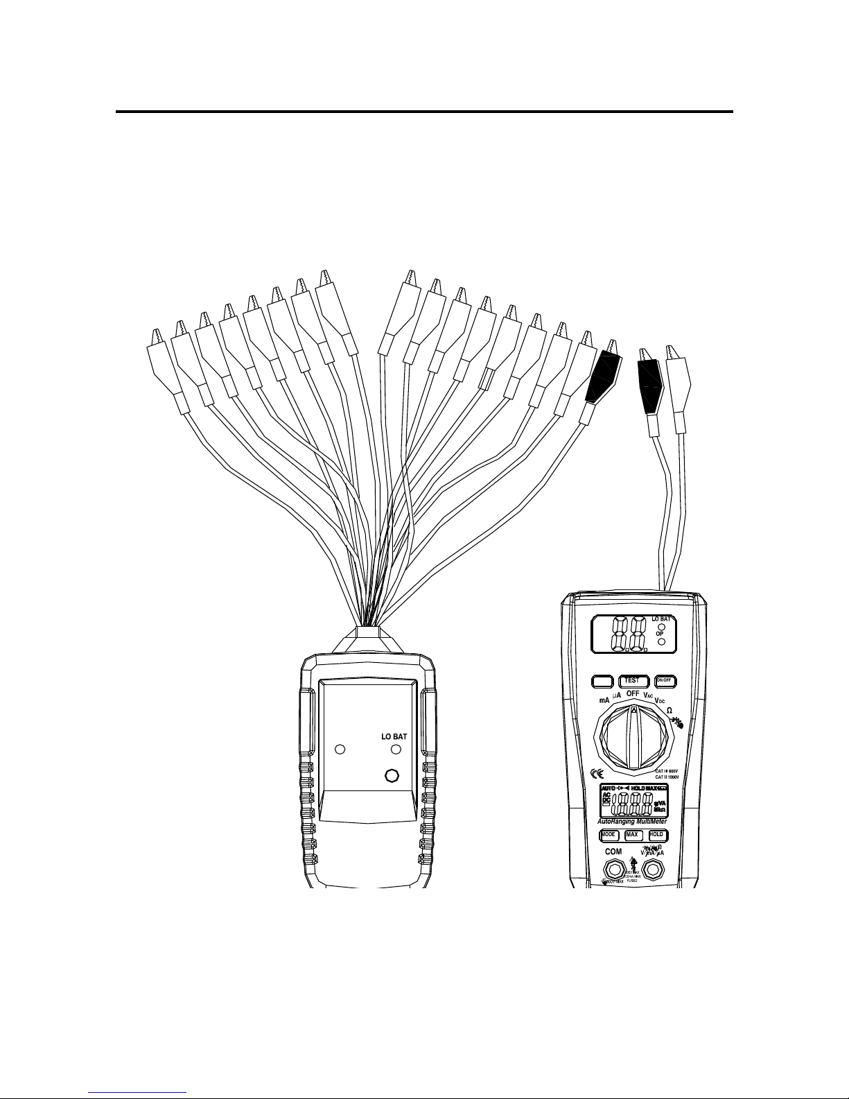
CABLE TESTER
CABLE IDENTIFIER
CABLE TESTER
CABLE IDENTIFIER
Vcheck
Page 2

2
TABLE OF CONTENTS
1.APPLICATIONS GENERAL--------------------------------------3
2.FRONT PANEL DESCRIPTION---------------------------------3
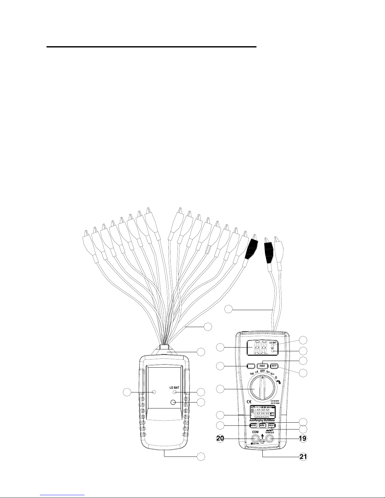
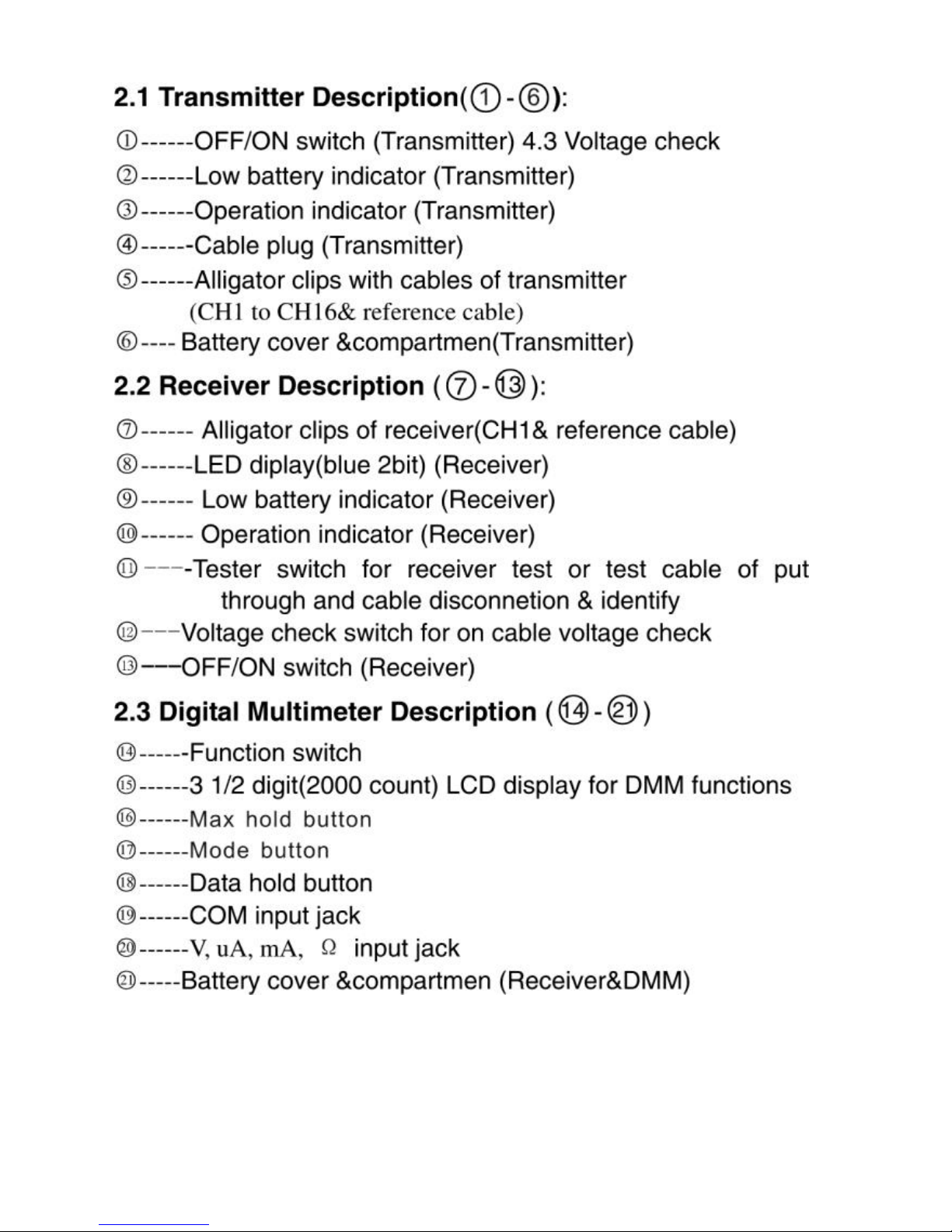
2.1 Transmitter Description---------------------------------------4
2.2 Receiver Description--------------------------------------------4
2.3 Digital Multimeter Description-------------------------------4
3. SPECIFICTIONS&TETHNICAL DATA------------------------4
3.1DMM----------------------------------------------------------- ----4-5
3.2Transmitter----------------------------------------------------------6
3.3 Receiver----------------------------------------------------- ------6
4.MEASURING PROCEDURE-------------------------------------7
4.1 Transmitter&Receiver operation-------- -------------------7
4.2 Beep alarm test-----------------------------------------------.---7
4.3 Voltage check------------------------------ ---------------------8
4.4 Digital Multimeter test--------------------------------------8-12
5.BATTERY REPLACEMENT------------------------------------12
Page 3
3
CABLE TESTER&DIGITAL MULTIMETER
Cable Identifier&DMM LA-1015
1.APPLICATIONS GENERAL
LA-1015 is a transmitter/receiver device which enbles
one person to instantly match up ends of indivdual
cores at either end of a multi-core cable .With the remote
kit it can tester cables installed far away either on wall
plate or patch panel .Digital multimeter function make it
easy to measure DC/AC voltage ,DC/AC current ,
Resist-ance,conTinuity &diode.
2.FRONT PANEL DESCRIPTION
OP
ON
CABLE TESTER
CABLE IDENTIFIER
CABLE TESTER
CABLE IDENTIFIER
Vcheck
1
2
3
4
5
6
8
12
14
15
17
7
9
10
11
13
16
18
Page 4
4
3. SPECIFICTIONS&TETHNICAL DATA
3.1 DMM:
Page 5

5
Function
Range
Accuracy
DC Voltage
200mV,
(0.5% rdg + 3d)
2.000V, 20.00V,
(1.0% rdg + 3d)
200.0V, 600V
(1.0% rdg + 3d)
AC Voltage
50-60Hz
2.000V, 20.00V
(1.0% rdg + 5d)
200.0V, 600V
(1.5% rdg + 10d)
DC Current
200.0µA, 2000µA
(1.5% rdg + 3d)
20.00mA, 200.0mA
(2.0% rdg + 3d)
AC Current
200.0µA, 2000µA
(1.8% rdg + 8d)
20.00mA, 200.0mA
(2.5% rdg + 8d)
Resistance
200.0
(0.8% rdg + 5d)
2.000k , 20.00k ,
200.0k
(1.2% rdg + 3d)
2.000M
(2.0% rdg + 5d)
20.00M
(5.0% rdg + 8d)
Max input voltage 600V AC/DC
Diode Test Test current 1mA max., open circuit
voltage of 1.5V typical
Continuity Check Audible signal if the resistance is <150
Display 2000 count 3 -1/2 digit LCD
Over range indication
LCD displays “OL”
Polarity Minus (-) sign for negative polarity.
Low Battery Indication “BAT” symbol
indicates low battery condition.
Input Impedance >7.5MΩ (VDC & VAC)
AC Response Average responding
ACV Bandwidth 50Hz to60Hz
Page 6

6
Auto Power Off 15 minutes (approximately)
Fuse mA, µA ranges; 0.2A/250V fast acting
Fuse
Batteries 9V battery and two “AAA” batteries
Operating Temperature 32oF to 104oF (0oC to 40oC)
Storage Temperature 14oF to 122oF (-10oC to 50oC)
Weight 308g
Size 162x74.5x44.0mm
Standard IEC61010-1 CAT III-600V Pollution degree II,
CE Approved
3.2 Transmitter:
Display Two red LED lamps
Aligators 17Croc clips-red*16,black*1
Cable resistance 30K Ohm max
Power 9V battery
Power current 1.8mA
Operating temperature 0℃ to 40℃(32℉ to 104℉)
Storage temperature –10℃ to 50℃(14℉ to 122℉)
3.3 Receiver:
Display Two digit blue LED display
Aligators 2Croc clips-red*1,black*1
Power 9V battery
Power current 23mA
Operating temperature 0℃ to 40℃(32℉ to 104℉)
Storage temperature –10℃ to 50℃(14℉ to 122℉)
Continuity test Beep if less than 100Ω
Page 7

7
Cable voltage check 5V to 16V DC
4.MEASURING PROCEDURE
4.1 Transmitter&Receiver operation
1).At one end of the cable, Connect one of the transmitter
terminals marked “CH1 to CH16”to each core of the cable
under tester.Connect the “COM”reference lead (black
alligator) of the transmitter to a core which is the only known
one.
2).At the other end of the cable ,connect the “COM
terminal”(black alligator) of the receiver.
When the “input terminal”(red alligator) of the receiver is
successively touched on the cores of the cable under test,the
relevant number of the way is indicated on the display of the
receiver(1-16).
Operation example 1: Cable trace test
Operation example 2: Metal water pipe trace test
CAUTION: Though the units already build in the
protection circuit,however do not apply voltage that over
50V(AC or DCV)toany alligator clips of
transmitter&receiver. Otherwise the instruments may
defect permanently.
4.2 Beep alarm test : “TEST”button to down use receiver of
2Croc clips connect cable of two port if cable is put through
will have beep sound.otherwise cable isn’t put through or isn’t
same a cable.
CAUTION: Beep if less than 100Ω
Page 8

8
4.3 Voltage check: “V check” button to down use receiver
of 2Croc clips.Black alligator connect the “COM”reference
other red alligator connect the cable port .if Two digit blue
LED display is “ UU ” prove cable have voltage .only check is
mainly voltage.
CAUTION: Check voltage range at 5V to 16V DC
4.4 Digital Multimeter test
AC/DC VOLTAGE MEASUREMENTS
1).Insert the black test lead into the negative COM terminal
and the red test lead into the positive V terminal.
2).Set the function switch to VAC or VDC position.
3).Connect the test leads in parallel to the circuit under test.
4).Read the voltage measurement on the LCD display.
CAUTION: Do not measure AC/ DC voltages if a motor
on the circuit is being switched ON or OFF. Large voltage
surges may occur that can damage the meter.
AC/DC CURRENT MEASUREMENTS
1).Set the function switch to the µA/mA position.
2).Insert the black test lead into the negative COM terminal
and the red test lead into the positive µA/mA terminal.
Page 9

9
3).For current measurements up to 2000µA DC/AC, set the
function switch to the mA position
4).Press the MODE button to indicate “DC” / “AC” on the
display.
5).Remove power from the circuit under test, then open up
the circuit at the point where you wish to measure current.
6).Touch the black test probe tip to the negative side of the
circuit.
Touch the red test probe tip to the positive side of the circuit.
7).Apply power to the circuit.
8).Read the current in the display
RESISTANCE MEASUREMENT
1).Set the function switch to the Ω position.
2).Insert the black test lead into the negative COM terminal
and the red test lead into the positive Ω terminal.
3).Touch the test probe tips across the circuit or part under
test. It is best to disconnect one side of the part under test so
the rest of the circuit will not interfere with the resistance
reading.
4).Read the resistance in the display
Page 10

10
WARNING: To avoid electric shock, disconnect power to
the unit under test and discharge all capacitors before
taking any resistance measurements. Remove the
batteries and unplug the line cords.
CONTINUITY CHECK
1).Set the function switch to the position.
2).Insert the black test lead into the negative COM terminal
and the red test lead into the positive Ω terminal.
4).Touch the test probe tips to the circuit or wire you wish to
check.
5).If the resistance is less than approximately 150Ω, the
audible signal will sound. If the circuit is open, the display will
indicate “OL”.
WARNING: To avoid electric shock, never measure
continuity on circuits or wires that have voltage on them.
DIODE TEST
1).Set the function switch to the position.
2).Press the MODE button to Touch the test probes to the
diode
Page 11

11
indicate on the display. under test. Forward voltage
will typically indicate 0.400 to 0.700V. Reverse voltage will
indicate “OL”. Shorted devices will indicate near 0V and an
open device will indicate “OL” in both polarities
MAX Hold button
To hold the highest reading on the LCD
1).Press the MAX hold button. The meter reading will not
change as readings change
2). Press the MAX hold button again to return to normal
operation.
Hold Button
The Data Hold function allows the meter to “freeze” a
measurement for later reference
1).Press the “DATA HOLD” button to “freeze” the display, the
“HOLD” indicator will appear.
2).Press the “DATA HOLD” button to return to normal
operation.
AUTO POWER OFF
The auto off feature will turn the meter off after 15
minutes.
REPLACING THE FUSES
1).Disconnect the test leads from the meter.
Page 12

12
2).Remove the protective rubber holster.
3).Remove the battery cover (two “B” screws) and the
battery.
4).Remove the four “A” screws securing the rear cover.
5).Lift the center circuit board straight up from the connectors
to gain access to the fuse holders.
6).Gently remove the old fuse and install the new fuse into the
holder.
7).Always use a fuse of the proper size and value (0.2A/250V
fast blow for the 200mA range).
8).Align the center board with the connectors and gently
press into place.
9).Replace and secure the rear cover, battery and battery
cover.
WARNING: To avoid electric shock, disconnect the test leads
from any source of voltage before removing the fuse cover.
5. BATTERY REPLACEMENT
1). Both for the transmitter or receiver,when the “Low
battery indicator” is lit,it is necessary to replace the
battery.Measur-
Ements may still be made several hours after the low
battery indicator
Page 13

13
2).Remove the bottom cover and secure the screw.
3).Replace old battery with fresh two 1.5V AAA or 9V type
batery.
4).Replace the bottom cover and secure the screw.
 Loading...