

Page 1
EDGE™
Energized Dispersive Guided Extraction
Manual
Page 2

THIS PAGE INTENTIONALLY LEFT BLANK
Page 3

Contents
Safety
Safety Notations 1
Introduction
About the Instrument 2
Important Safeguards
Instrument Safeguards 3
Sample Preparation Safeguards 3
Heating Safeguards 3
Instrument Overview
Front and Side View 4
Back and Side View 5
Software Overview
Software Icons 6
Home Screen 7
Methods Screen (One Touch and User) 7
System Menu 8
System Installation
Unboxing 11
System Setup 11
Methods
Create Method 31
Edit Method 34
Copy Method 34
Delete Method 34
Export Method 35
Import Method 35
Users
Create User 36
Edit/Delete User 37
Auto Login 37
Logs 37
Data Management
Export Data 38
Search Data 39
Calibrations
Verify Waste Calibration 41
Pressure Calibration 42
Verify Autosampler Calibration 43
Autosampler Calibration 44
Temperature Calibration 47
Sample Analysis
Sample Preparation 20
Prepare the EDGE 21
Load Method 21
Run Sample 22
Sample Removal and Cleanup 24
Bottle Setup & Configuration
Solvent Compatibility 25
Add Solvent 25
Edit Solvent 26
Delete Solvent 27
Assign Solvent Bottle Positions 27
Q-Discs
Enter Q-Disc Code 29
Q-Disc Comparison Guide 30
Utilities
Prime Solvent Lines 49
System Purge 50
Software Update
How to Update Software 51
System Repacking
Prepare to Ship 53
Routine Maintenance
Daily 55
Monthly 55
Annually 56
Page 4

Troubleshooting
Problems and Possible Solutions 57
Clog Check 57
Clog Recovery 59
System Specifications
Location Requirements 60
Electrical Requirements 60
Environmental Requirements 60
Warranty
Limited Warranty Information 61
Technical Assistance
Applications Support 63
Technical Support 63
Contact Information
CEM Corporation Headquarters 64
CEM International Subsidiaries 64
CEM Distributors 65
Page 5
Safety
Safety Notations
This manual uses three safety alert words at points in the documentation where the user should be aware of
potential hazards. The safety alerts are shown in color-coded boxes. The three words – NOTE, CAUTION, and
WARNING – indicate differing levels of observation or action as described below:
NOTE
A NOTE is intended to provide emphasis on procedures that may be misinterpreted or overlooked, or to
clarify confusing situations.
CAUTION
A CAUTION is intended to provide essential information and to emphasize procedures that, if not strictly
followed, may result in improper instrument operation.
WARNING
A WARNING is intended to emphasize dangerous or hazardous conditions that may result in personal
injury to the user and/or damage or destruction of the instrument.
PINCH POINT
A PINCH POINT is intended to keep hands clear during operation and if not avoided, could result injury.
HOT
Surface is hot to the touch.
1Safety
Page 6

Introduction
About the Instrument
The EDGE is the most advanced automated solvent extraction system available. By combining pressurized uid
extraction and dispersive solid phase extraction, the EDGE is able to drastically reduce sample preparation time
and the potential for human error. The result is fast, simple, and efcient extractions.
This manual is intended for use by both novice and experienced users for the operation and maintenance of the
EDGE automated extraction system. Additional information, including but not limited to: training notes and videos,
application notes, software updates, and parts can be viewed on CEM’s website at http://cem.com/edge.
This manual refers to EDGE software version 1.16 for all software information, including screenshots and technical
information.
This Manual should be used in conjunction with the EDGE Site Prep Guide (P/N FM0067) and EDGE Packing
Guide (P/N 600940.) Read and fully understand all documentation before operating the instrument.
2 Introduction
Page 7

Important Safeguards
General guidelines for safe operation of the EDGE system are presented below and all specic safety messages
are located throughout the manual.
Proper precautions must be taken to avoid contact with reagents or reagent vapors. Protective gear should be worn
as outlined in the user’s safety program for hazardous materials and the reagent manufacturer’s safety data sheet.
Refer to these guidelines for proper handling and disposal of the reagents. Dispose of all waste in accordance with
all applicable local, state, and federal health and safety recommendations.
Instrument Safeguards
• Service can only be performed by an authorized CEM service technician. The system must be disconnected
from power supply prior to servicing.
• Do not tamper with the EDGE, including actions such as removing any components of the housing or
manually trying to move the automation components.
• The exhaust hose must be connected and draw at least 30.5 CFM at the point of connection at all times as
it is essential for removing harmful gases away from the EDGE instrument. Vapors should be vented into a
fume hood by means of the exhaust hose only.
• NEVER place hands or any object into the automation area from the time “Start” is selected until the system
is idle.
• Do not place hands or objects in the actuator (vessel chamber) area unless instructed to do so.
• Only load or unload rack when the EDGE is in the idle state or instructed to do so.
• If any damage to the instrument is noted, do not attempt instrument operation.
• Vessel Chamber area may be hot.
• Use only CEM specied consumables and accessories.
Sample Preparation Safeguards
• Q-Cups and Q-discs must be purchased directly from CEM Corporation or through its authorized dealer
network.
• Proper precautions must be taken to avoid contact with reagents or reagent vapors. Protective gear should
be worn as outlined in the user’s safety program for hazardous materials and the reagent manufacturer’s
safety data sheet. Refer to these guidelines for proper handling and disposal of the reagents.
• Do not ll sample above the outer band of the Q-Cup
• For plastic samples, always stay below the melting point.
• The EDGE is not compatible with any strong acids or bases.
Heating Safeguards
• Ensure that the pressure of the solvent at the maximum set temperature is less than 200 psi.
• Observe Preheat Temperature - the temperature the chamber heats to prior to running each extraction.
• If the method temperature is 100 °C or above, a preheat temperature of 100 °C is recommended.
• If the method temperature is less than 100 °C, the preheat temperature should be the method
temperature.
• The preheat temperature cannot be set lower than room temperature.
• A preheat temperature higher than the set point of your methods will lead to a system error.
• Preheat temperature can be changed in settings.
3Important Safeguards
Page 8
Instrument Overview
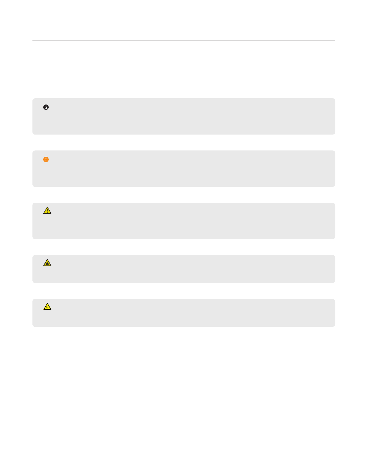
Front and Side View
4
10
9
8
6
3
2
Item
1 Touch Screen Display
2 USB Ports (3)
3 Ethernet Port
4 Speaker
5 Autosampler Automation area
6 Power Switch
7 Dispense Needle
8 Removable Rack
9 Vessel Chamber
10 Actuator
11 Safety Enclosure
11
7
5
1
4 Instrument Overview
Page 9
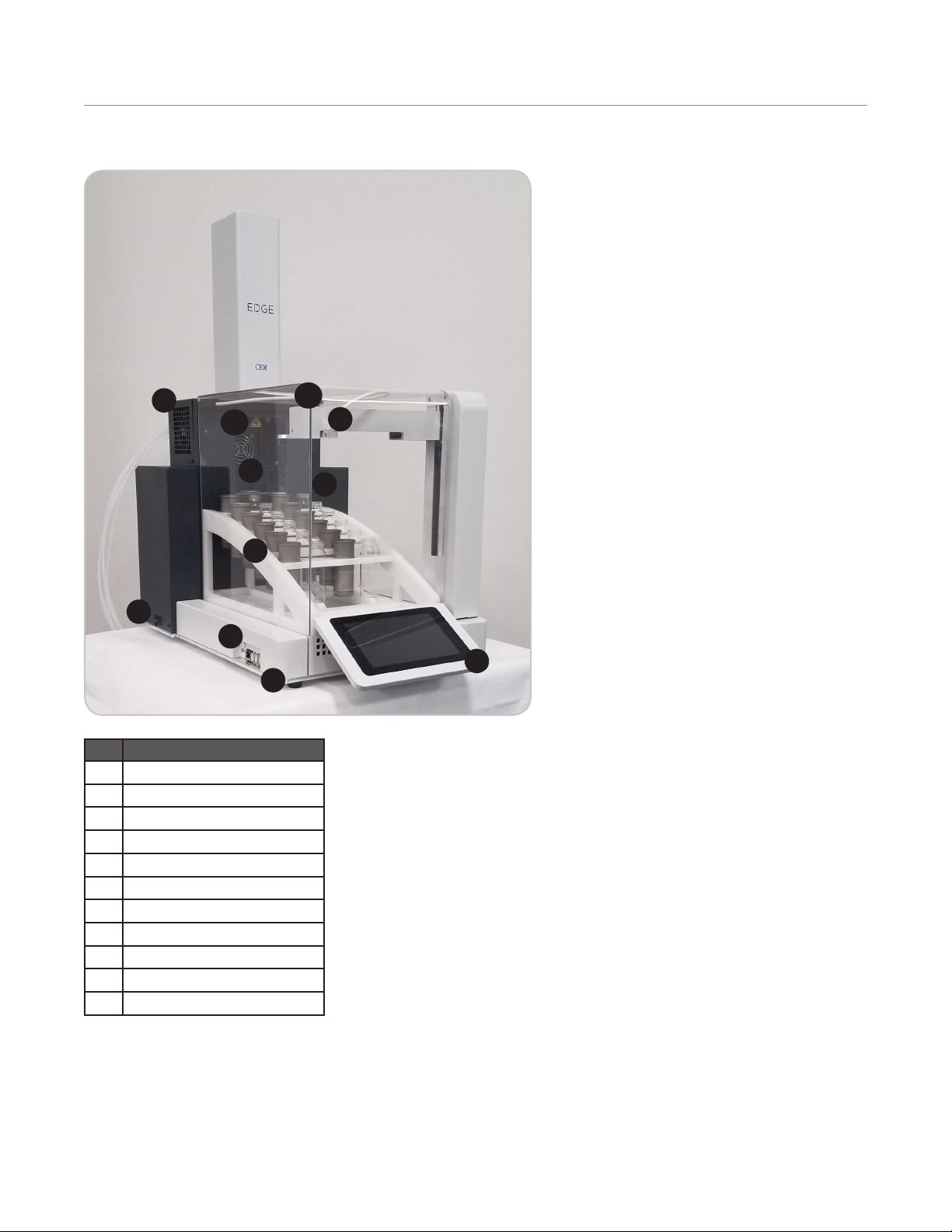
Back and Side View
3
Item
1 Fuses/Fuse Holder
2 Power Inlet
3 Exhaust Assembly
4 Cooling Fan
5 Fluidics and Manifold
6 Solvent Lines
7 Waste (Vent, Drain & Sensor)
7
5
6
4
1
2
5Instrument Overview
Page 10
Software Overview
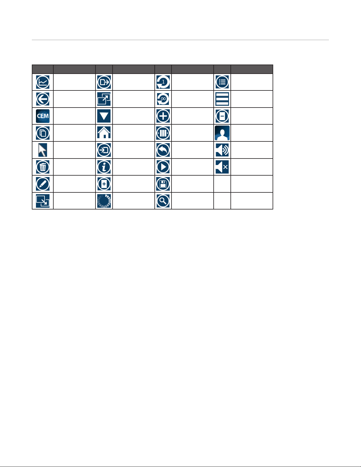
Software Icons
Icon Description Icon Description Icon Description Icon Description
Advanced View Export Loop 1 Simple View
Back Full Screen Loop Innity System Menu
CEM Method Hide Keypad New Unload Rack
Methods
Copy Home Queue User Method
Cursor Import Revert Volume High
Delete Information Run Volume Mute
Edit Load Rack
Methods
Exit Full Screen Loading Search
Save
6 Software Overview
Page 11
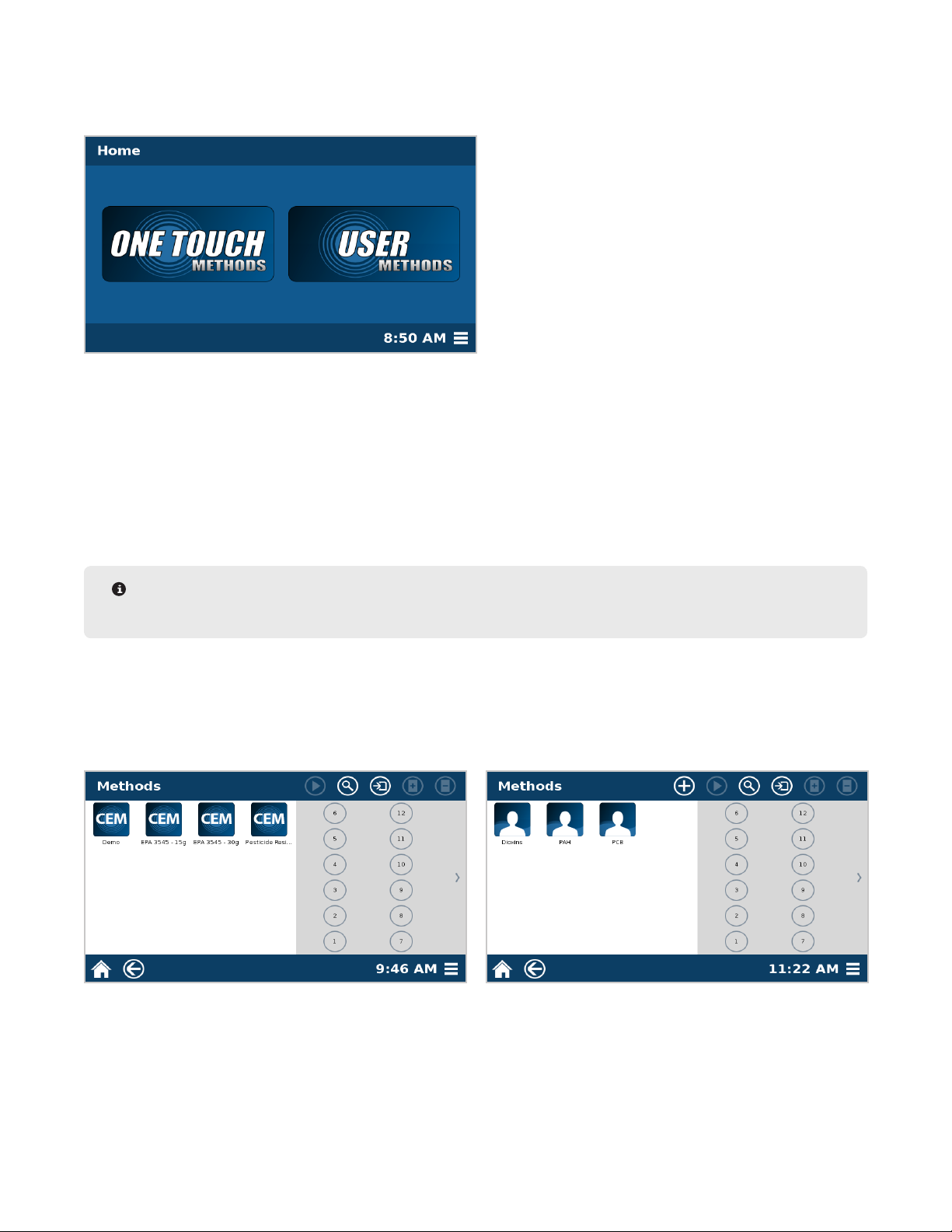
Home Screen
The Home screen is the rst screen that appears when the system is turned on. Three areas are accessible from
this screen: One Touch® Methods, User Methods, and System Menu.
• One Touch Methods are methods created and optimized by CEM for a variety of sample types in an effort to
reduce method development time required of user. These methods cannot be edited, but they can be copied into
the User Methods area, where the parameters can be edited.
• User Methods are created by the user and can be edited at any time. These methods are typically for users with
unique or specialized products that do not obtain optimal results using a One Touch Method. User Methods can
be imported from another instrument.
• The System Menu icon provides access to any functionality that does not directly involve creating or running a
method on the EDGE.
NOTE
A log-in screen may appear if an administrator turns auto-login to “off” in the “Users” -> “Settings” menu.
Methods Screen (One Touch and User)
After choosing either the One Touch Methods (left) or User Methods (right), the method library and vial rack
conguration will appear. Selecting a method will allow you to either select a position to begin running your
samples or additional options, which are detailed in this manual.
7Software Overview
Page 12
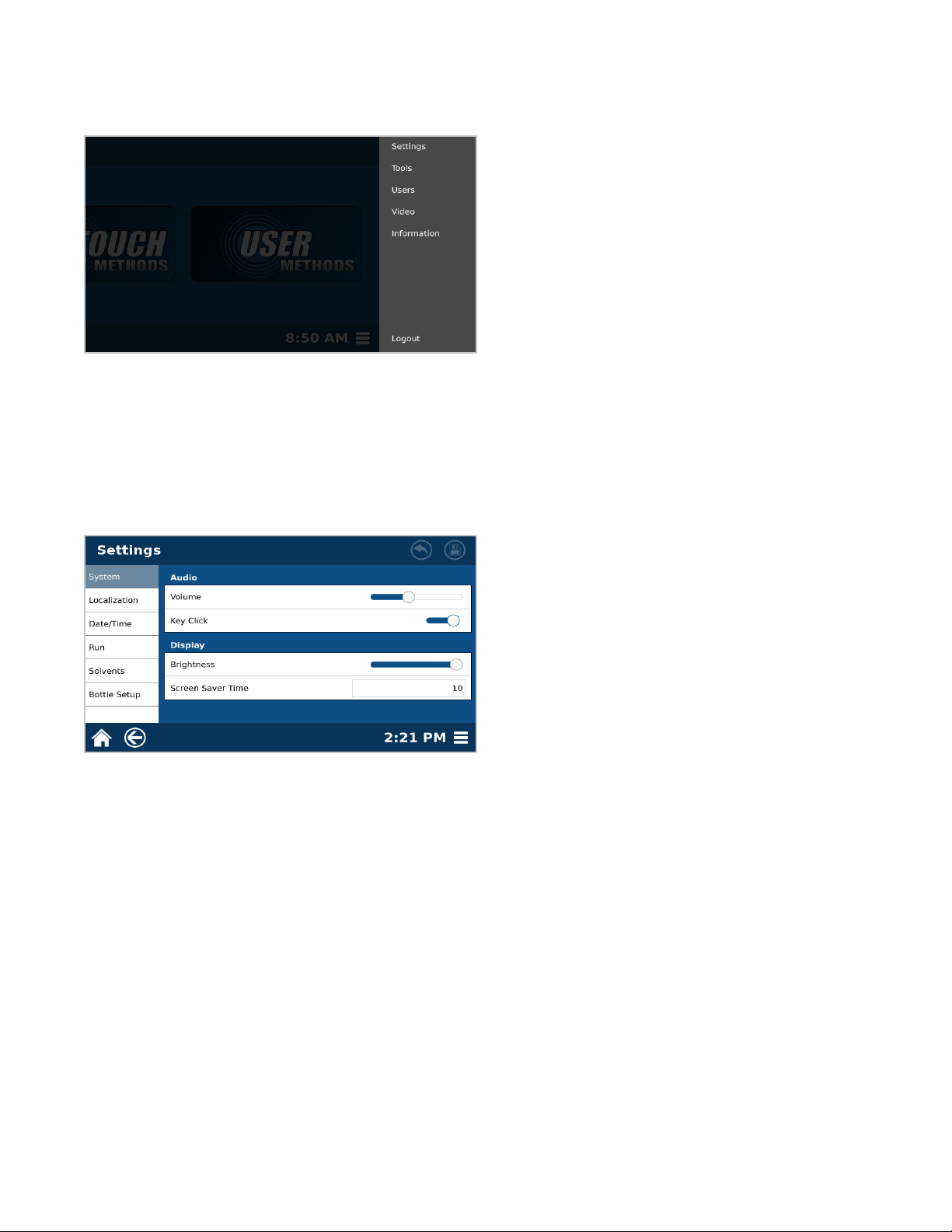
System Menu
The following is a basic review of each section of the System Menu to be used as a quick guide for locating
software items and instrument functions.
• Settings: Adjustable system settings necessary prior to running samples
• Tools: Calibration and Diagnostic tools to ensure proper system functionality
• Users: Location for creating and deleting different user accounts, as well as reviewing user logs if necessary
• Video: Videos for ensuring proper system handling and usage
• Information: System information including serial number, software version, contact information, etc.
Settings
• System: Instrument settings for the audio and visual selections for the individual user
• Localization: Regional adjustments, including language and the preferred date and time format
• Date/Time: Location for setting the correct date and time
• Run: Adjustments to settings specic to each sample run including: sample ID format, test completion
indicators, preheat temperature
• Solvents: List of solvents, where new solvents can be added, changed and deleted
• Bottle Setup: Location for identifying which solvent line corresponds to a particular bottle of solvent
8 Software Overview
Page 13
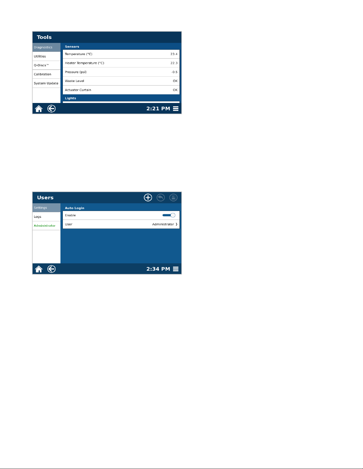
Tools
• Diagnostics: A listing of real-time readings for many of the sensors and parts directly related to unit functionality,
the option to manually maneuver the actuator, fan, pump and autosampler and turn lights ON/OFF
• Utilities: Functionality to ensure system is operating properly and to prepare the system for shipping
• Q-Discs: Add Q-Discs by barcode scanner or manually
• Calibration: Calibration of the temperature, pressure, or autosampler
• System Update: Used for updating software when a new version is released
Users
• Settings: Turning ON/OFF auto-login requirements for users
• Logs: Audit trail for tracking user movement within software, including system and method editing
• Administrator: List of users are located beneath logs
9Software Overview
Page 14
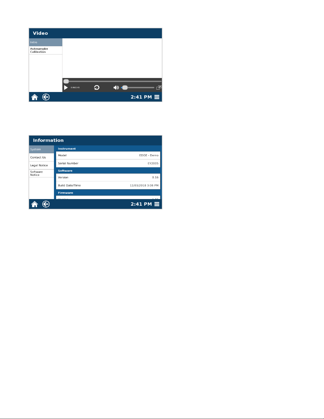
Video
• Videos provide helpful information about the EDGE to ensure proper system handling and usage
Information
• System: Reference for serial number, software and rmware versions, and calibration dates
• Contact Us: Contact for CEM Headquarters and Subsidiaries
• Legal Notice: Legal information concerning the use and distribution of the EDGE and other CEM products
• Software Notice: System notication pertaining to the software currently loaded on the system
10 Software Overview
Page 15
System Installation
Unboxing
1. Carefully inspect the shipping carton, the instrument and accessories for any damage that may have occurred
during shipping. If the instrument or accessories have damage, contact the freight carrier to report the damage
and le a damage report. Contact the CEM Service Department (inside the US 1-800-226-5228) or the nearest
subsidiary or distributor (listed on www.cem.com/contact.html) to request service information.
WARNING
If any damage to the instrument is noted, do not attempt instrument operation.
2. Refer to the Packaging guide (P/N 600940) for detailed instructions on unboxing the EDGE.
System Setup
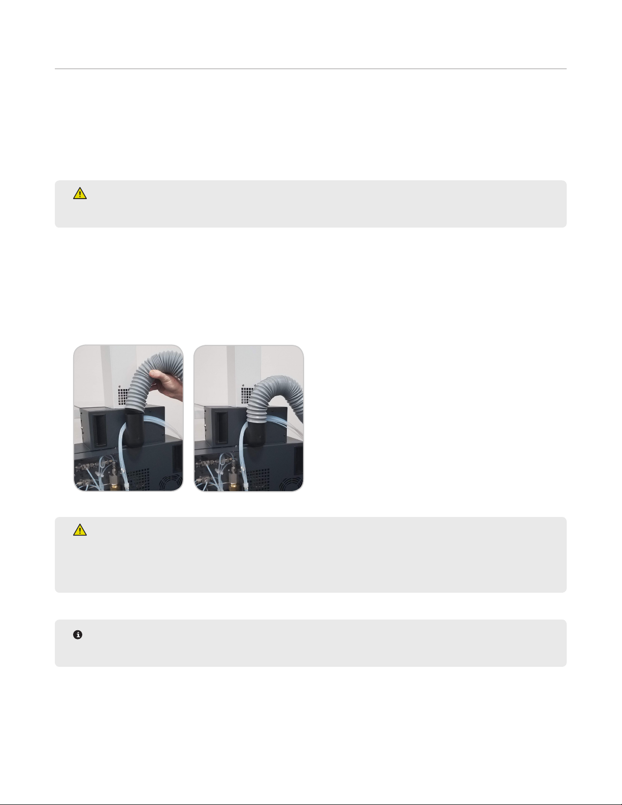
1. Attach the exhaust tubing to the exhaust output located on the rear of the system. The exhaust tubing is sup-
plied in the EDGE accessory kit. The fume hood or exhaust line must draw at least 30.5 CFM at the point of
connection and be no further than 10 foot away.
WARNING
The exhaust hose must be connected and draw at least 30.5 CFM at the point of connection at all times
as it is essential for removing hazardous fumes and vapors away from the EDGE instrument. Vapors
should be vented into a fume hood by means of the exhaust hose only.
NOTE
An outside gas source is not required to setup or run the EDGE.
2. Plug the power cord into the instrument and the dedicated electrical receptacle. The instrument is supplied
with a power cord, but an adequately rated power cord may be used.
3. Position the EDGE so there is open space to access the power switch and the racks can be easily loaded.
11System Installation
Page 16
4. Install the barcode scanner.
4.1. Open the box containing the barcode scanner.
4.2. Locate the barcode USB key and insert it into the USB slot on the left side of the EDGE.
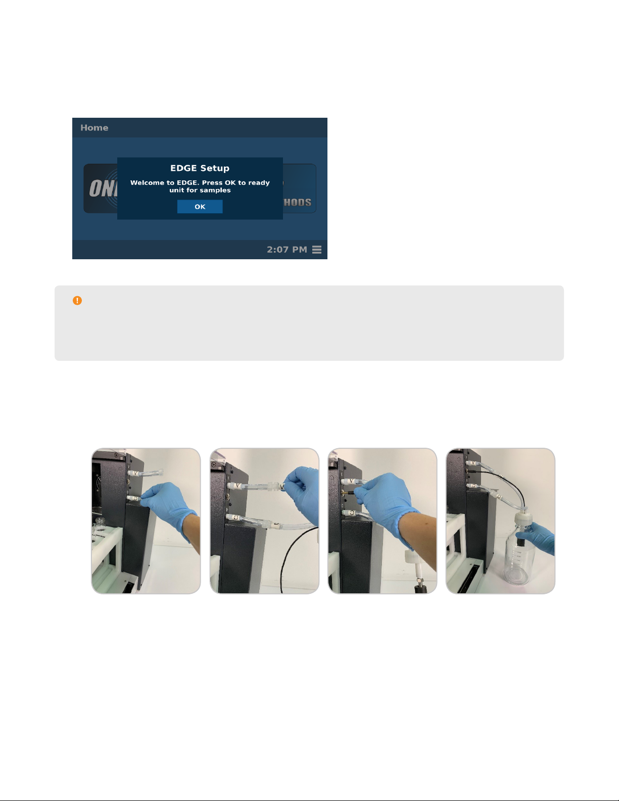
5. Locate the power switch on the left side of the instrument, and position it in the ON position.
6. When the system is rst powered on during the install, a welcome message will appear. Follow the prompts in
the software to complete EDGE Setup.
CAUTION
Remove both brackets as shown on the software screen with a screwdriver. Insert screws into the EDGE
once nished and store brackets with packaging. The brackets will be needed if the EDGE needs to be
shipped/transferred.
7. Attach the bottles.
7.1. Attach the white bottle cap with waste sensor to the EDGE. Note the labels on the tubing extending from
the waste cap and connect to the appropriate positions on the EDGE system: V= Vent, D=Dispense, and
Black cord supplies power.
7.2. Attach waste bottle.
7.3. Add solvent to the appropriate bottles. Up to 6 bottle positions can be used.
7.4. Secure the blue bottle caps (GL45) onto the solvent bottles.
7.5. Thread the solvent tubing attached to the EDGE through the appropriate solvent bottle cap. Ensure tubing
reaches the bottom of the solvent bottle.
12 System Installation
Page 17
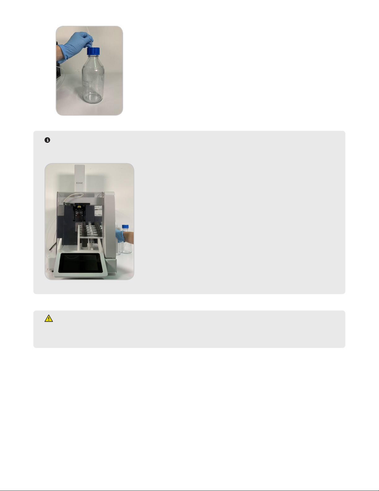
NOTE
The solvent lines are labeled 1-6. Be aware of which solvent line is in which solvent, as this information
will be used in “Bottle Setup and Conguration.”
WARNING
Do not tamper with the EDGE, including but not limited to removing any components of the housing or
manually trying to move the automation components.
8. The System Recovery screen may appear. Proceed with steps below if System Recovery screen appears.
13System Installation
Page 18

8.1. Ensure that the autosampler is in a safe position. An example of an unsafe location would be if the fork is
in a compromised position where it will crash into something if the autosampler attempts to move home.
• If this is the scenario, use the arrows to move the autosampler to a safe location before selecting “OK”.
CAUTION
Use caution when manually controlling the X, Y, and Z Controls. There are three distances for the
autosampler. If you need to move the autosampler a short distance, select Ultra-ne. If you need to move
it a moderate distance, select Fine, and select Coarse if you need to move a large distance. You can hold
down the arrows for constant movement. There are three coordinates: X moves the autosampler from left
to right, Y moves the autosampler forward and back, and Z moves the autosampler up and down.
8.2. Select “OK” to home the autosampler. The automation will rise up, towards the display, then to the left and
then backwards.
WARNING
NEVER place hands or any object into the area containing the rack while the EDGE is running a method or
while the autosampler is in motion. Only load or unload rack when the EDGE is in the idle state.
8.3. Select “OK” to open the actuator.
14 System Installation
Page 19
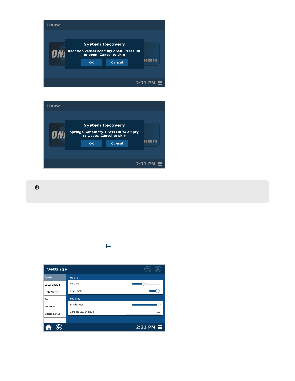
8.4. Select “OK” to empty the syringe to waste.
NOTE
In order for the system to empty the syringe, the waste bottle and sensor must be connected.
8.5. System recovery is complete; select “OK.”
9. Once “EDGE Setup” is complete and the autosampler is home, insert the rack.
9.1. From the right side of the EDGE, slide the rack into place. The rack is in the proper positions once the
magnets hold it securely in place.
10. Customize System settings.
10.1. Select the System Menu icon in the bottom right corner of the screen.
10.2. Select Settings.
10.3. Select the Localization tab.
15System Installation
Page 20
10.4. If English is not the preferred language, select Language to scroll through, and select the applicable system language.
NOTE
If the language is changed, the EDGE will reboot once the Save icon is selected.
10.5. Select Date Format to enter the desired format for displaying the date (MM/DD/YYYY, DD/MM/YYYY, or
YYYY/MM/DD).
10.6. Select Time Format to enter the desired format for displaying the time (12 Hour or 24 Hour).
10.7. Select the Date/Time tab, and set the correct Date and Time.
10.8. Additional System Settings can be adjusted at this time.
11. Verify Autosampler Calibration.
11.1. Select the System Menu icon in the bottom right corner of the screen.
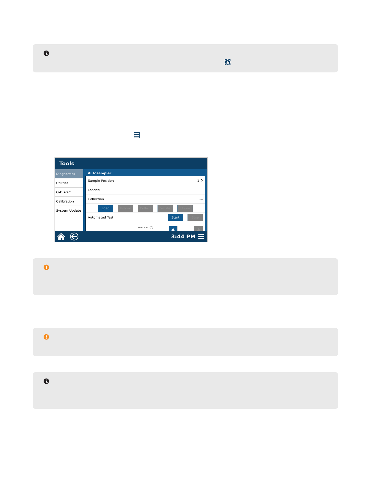
11.2. Select Tools.
11.3. Scroll down to the bottom of the page to the Autosampler section.
CAUTION
When verifying the autosampler calibration, always select “Load,” “Collect,” and “Unload” in that order
without skipping a function.
11.4. Place an assembled Q-Cup and collection vial/tube in position 4 of the rack. Remove the cap from the
vial/tube before placing in autosampler.
CAUTION
Remove cap from the vial/tube to prevent autosample obstructions and to allow extract collection.
NOTE
Position 4 is used to verify the calibration. Moving the Q-Cup to and from this location requires the most
distance traveled for all axes and is therefore the best test for the calibration.
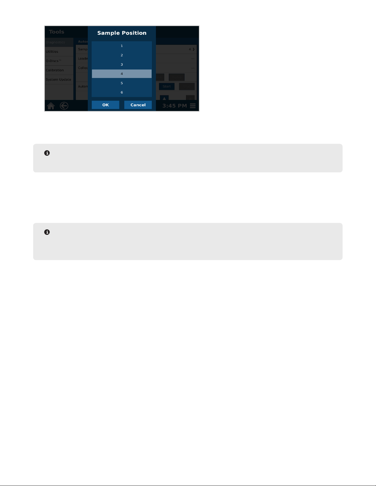
11.5. Select “1” from Sample Position to display the sample position menu.
16 System Installation
Page 21
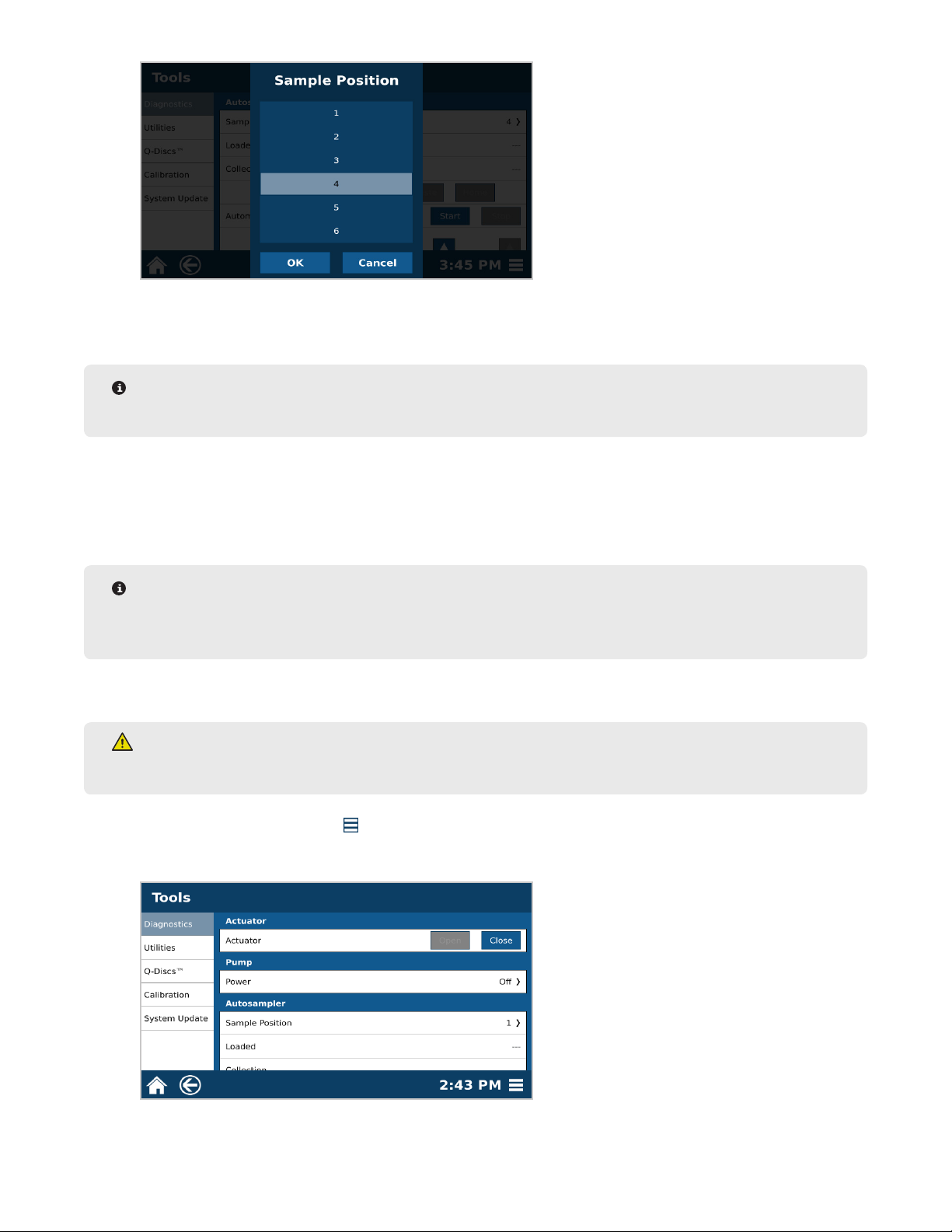
11.6. Select position “4” and then “OK.”
11.7. Select “Load.” The autosampler will load the Q-Cup into the vessel chamber.
NOTE
Pay attention to the Q-Cup during this time; the loading process should be smooth.
11.8. Select “Collect.” The dispense needle on the autosampler will move from the chamber to the collection
vial in position 4 of the rack.
11.9. Select “Unload.” The autosampler will unload the Q-Cup from the vessel chamber and place it back into
position 4 of the rack.
NOTE
If the autosampler crashes at any point during the verication, the autosampler will need to be calibrated.
Please see “Autosampler Calibration.”
12. Verify the Waste Calibration.
WARNING
Never place hands into the vessel chamber area when the EDGE is in use or powered on.
12.1. Select the System Menu icon in the bottom right corner of the screen.
12.2. Select Tools.
12.3. Select the Diagnostics tab and view the “Actuator” section.
17System Installation
Page 22
12.4. Select “Close.”
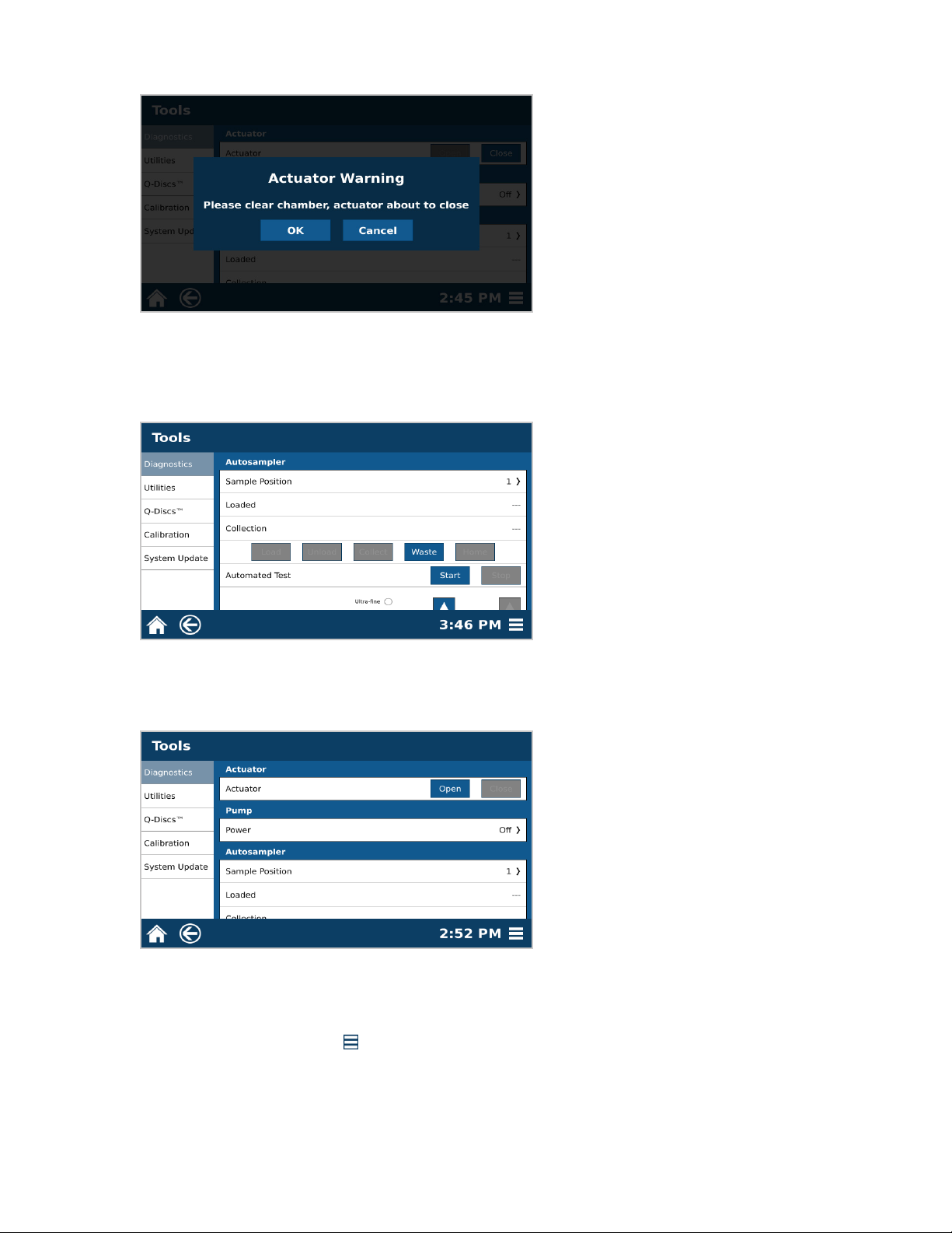
12.5. A warning will appear. Select “OK” once chamber is clear.
12.6. Scroll down to the Autosampler section. Select “Waste.” The autosampler dispense needle will travel to
the waste position. Observe the movement of the autosampler at this time. The dispense needle should
glide smoothly in to the waste port. If movement is not smooth the waste position will need to be calibrated.
12.7. Select “Home.” The autosampler will travel to the home position.
12.8. Scroll upward to the Actuator section.
12.9. Select “Open.”
12.10. If the autosampler crashes at any point during the verication, the autosampler will need to be calibrated.
Please see Calibrations section of this manual.
13. Calibrate Pressure.
13.1. Select the System Menu icon in the bottom right corner of the screen.
13.2. Select Tools.
13.3. Select Calibration.
18 System Installation
Page 23

13.4. Select Pressure “Calibrate.” This will take less than a minute.
13.5. Select “OK.”
14. System Setup is complete.
19System Installation
Page 24
Sample Analysis
Sample Preparation
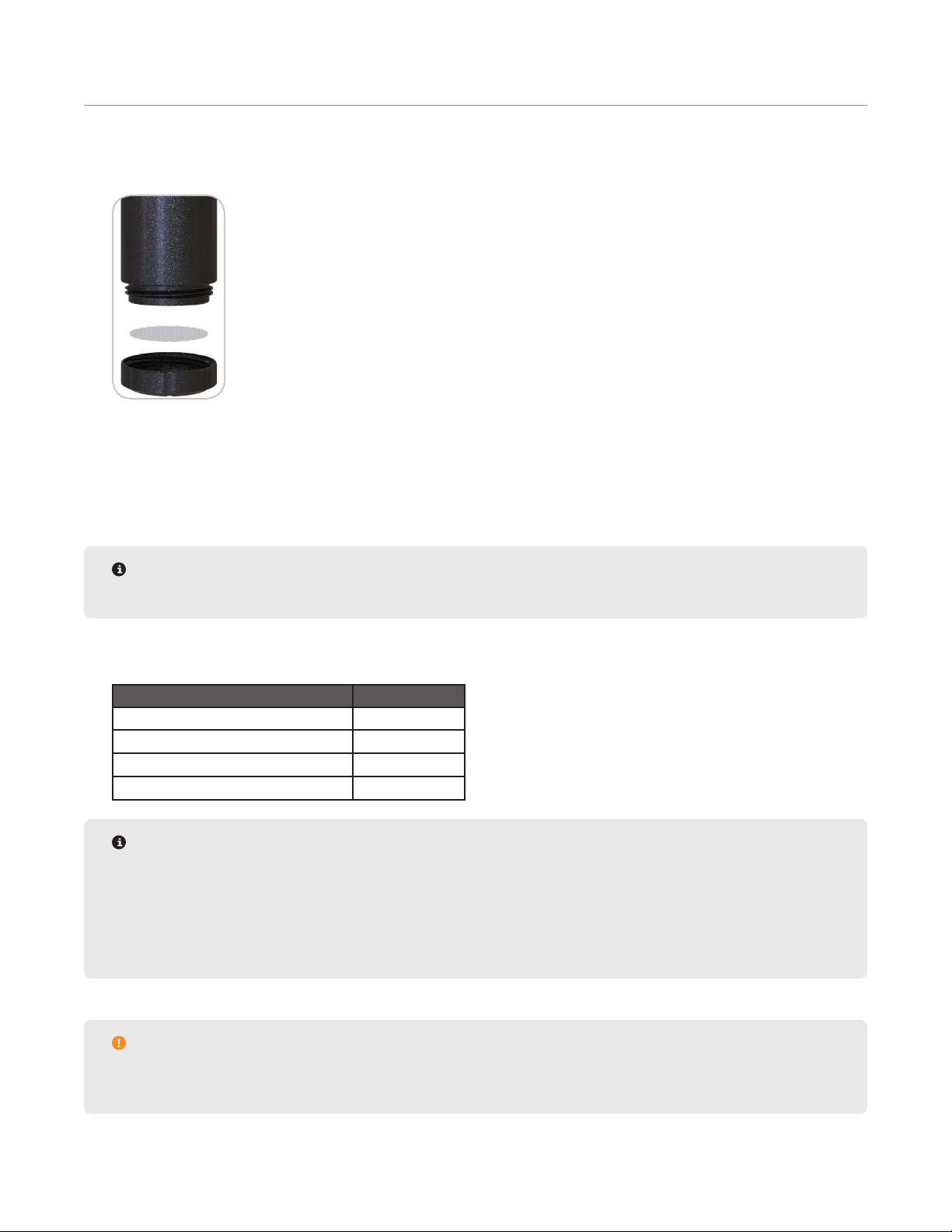
1. Add a Q-Disc to a clean Q-Cup.
1.1. Remove bottom of Q-Cup by unscrewing.
1.2. Place Q-Disc into bottom piece of Q-Cup.
1.3. Place top piece of Q-Cup onto bottom piece and twist together until nger tight.
2. Weigh any sorbents, if needed for inline sample drying or cleanup, into Q-Cup.
NOTE
Do not add wet sample directly to the Q-disc, make sure sorbent/drying agent is placed rst.
3. Weigh sample into Q-Cup. The maximum sample size should be below the outer band of the Q-Cup that sits on
the rack. Suggested sample weights are listed below.
Sample Weight Maximum (g)
Food, Plant, and Animal Tissue 30
Oil and Plastic 2
Environmental and Regulatory 5
Miscellaneous 5
NOTE
The Q-Cup can only handle solid and semi-solid samples up to 30 grams, no liquids can be used. To
determine if the sample will t in the Q-Cup, add sample to a graduated cylinder; the Q-Cup can hold 50
mL. If the sample is above 50 mL, it will not t in the Q-Cup.
Mix dry samples with sand to disperse sample for better draining.
CAUTION
Overlling may cause clogging, as it allows excess pressure to develop. DO NOT ll sample above the
outer band of the Q-Cup.
20 Sample Analysis
Page 25
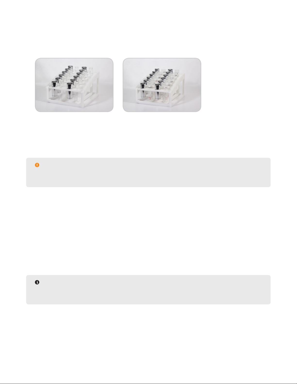
4. Prepare up to 12 samples per rack to be run in series.
Prepare the EDGE
1. Load Q-Cups and collection containers on rack. The software will detect if a Q-cup is not in place but cannot
detect if the collection containers are missing.
• Glass vials or Centrifuge tubes may be used for the collection containers but must be accompanied by the
appropriate rack
• Centrifuge Tube Rack (P/N 525135)
• Glass Vial Rack (P/N 525080)
• Up to 24 methods (2 racks of samples) can be loaded at a time
CAUTION
Remove the cap(s) from the vial(s)/tube(s) to prevent autosample obstructions and to allow extract
collection.
2. Place rack on the EDGE platform and slide into position until magnets lock.
3. Verify solvent bottle positions. See “Assign Solvent Bottle Positions” section for more details.
4. Ensure there is enough solvent in the solvent bottles.
5. Ensure there is enough room in the waste bottle.
6. Verify Q-Disc codes in software to determine if runs are available. See “Q-Discs” for detailed instructions.
Load Method
1. Load Methods.
• To Load a single method in a position: Select desired method and then select the position on the rack.
Continue selecting methods and rack positions.
NOTE
A specic method can be assigned to each sample. Up to 12 methods can be run per rack. The system
will run the samples in numerical order, not in the order in which they were selected.
21Sample Analysis
Page 26

NOTE
A two cycle method with a total solvent volume greater than 40 mL will populate into two positions. You
will need to prepare one Q-Cup and two collection vials.
rack sequentially as shown in the image below.
• To populate all positions with a single method: Select desired method followed by the Load Rack icon in
the top right corner of the screen. Select the right arrow to the right of the rack. Notice that all 24 samples
have been selected.
2. Load methods for up to a batch size of 24 samples.
The two collection vials must be placed on the
NOTE
The “Batch Size” can be assigned as 12 or 24 in the software. The batch size can be changed in the
following location: Settings > Run > “Batch Size. A batch size of 24 will require 2 racks.
3. The Preheat Temperature will appear in the lower portion of the screen if the temperature is greater than 50
°C. The Preheat Temperature is the temperature the chamber heats to prior to running each extraction. The
Preheat Temperature can be changed in the following location: Settings > Run > “Preheat”.
• If the method temperature is 100 °C or above, a Preheat Temperature of 100 °C is recommended.
• If the method temperature is less than 100 °C, the Preheat Temperature should be the method temperature.
• The Preheat Temperature cannot be set lower than room temperature.
• A Preheat Temperature higher than the set point of your methods will lead to a system error.
Run Sample
1. Select the Run icon at the top of the screen.
NOTE
All caps must be removed from collection tubes/vials prior to running samples.
2. Add a Sample ID if desired. The Sample ID for the rst method needs to be loaded prior to starting, other Sample IDs can be added after.
22 Sample Analysis
Page 27

2.1. Select the sample to give a sample ID.
2.2. Select the position/sample you would like to assign a name to and give the sample a unique name using
the keypad.
2.3. Select “OK.”
NOTE
If a sample ID is not assigned, the sample prex and number assigned in the database will be used. The
Sample ID can be changed in the following location: Settings > Run > “Prex” and “Number”.
3. Select “Start.” The EDGE will run all samples loaded in numerical order of the sample positions on the rack.
WARNING
The EDGE operates at temperatures and pressures up to 200 ºC and 200 psi.
NEVER place hands or any object into the automation area from the time “Start” is selected until the
system is idle.
NOTE
To display the temperature and pressure graph, select the Advanced View icon on the top right corner of
the screen.
4. During analysis the user can view the sample queue by selecting the Queue icon in the top right corner.
• Samples that are in the queue are green. Samples in green can be selected to remove from the queue;
these samples will no longer run.
• Samples that are running are dark blue.
• Samples that have already run are light blue.
5. If more than one rack is being run, the following message will be displayed once the rst rack is nished.
Change the rack BEFORE selecting “OK.”
23Sample Analysis
Page 28

CAUTION
The software will continue running methods in the queue for the second rack once “OK” is selected, even
if the second rack was not inserted.
Sample Removal and Cleanup
1. Remove the rack.
WARNING
The Q-Cup(s) may still be hot to touch.
2. Remove collection container from rack. Collected extracts are cooled, ltered, and ready for analysis.
3. Remove Q-Cup from rack and discard Q-Disc and sample.
4. Clean Q-Cups with organic solvent. Optional cleaning procedures are outlined below using LUMINOX or pH-neu-
tral and aluminum-safe cleaner.
• Hand wash with warm soapy water
• Sonicator
• Automated dishwasher
24 Sample Analysis
Page 29

Bottle Setup & Configuration
Solvent Compatibility
The EDGE is compatible with any solvent. Below is a list of some solvents with their characteristics and
applications. Note that these are not the only solvents compatible with the EDGE and these are not the only
applications that these solvents can be used for. The EDGE can handle a pH range of 4-9. The EDGE is not
compatible with strong acids or bases.
Solvent Polarity Boiling Point (°C) Vapor Pressure (kPA) Application
Water Most Polar 100 2.4 Nutraceuticals
Methanol 64.6 16.9 Plastics
Acetonitrile 81.65 9.9 Pesticide Residues
Acetone 56.2 30 Environmental
Dichloromethane 39.8 58 Environmental
Toluene 110.6 3.8 Dioxins
Petroleum Ether 30-60 31 Total Fat
Hexane Least Polar 69 17.6 Environmental
WARNING
The EDGE is not compatible with strong acids or bases.
Add Solvent
Each Method will require a solvent for cycle parameters and wash method. The EDGE has 6 bottle positions
that solvents cans be assigned to and can be used per method. See section below to add additional solvents or
solvent mixtures to the database.
1. Select the System Menu icon in the bottom right corner of the screen.
2. Select Settings.
3. Select Solvents.
4. Select the New icon in the upper right corner of the screen. A pop-up will appear.
25Bottle Setup & Conguration
Page 30

5. Enter the solvent parameters: Name, Max Temp, and Cooling Temp.
• The Max Temp is the maximum temperature a method using the solvent can be set to.
WARNING
Ensure that the pressure of the solvent at the maximum set temperature is less than 200 psi. If unsure of
the Max Temp and Cooling Temp parameters, please contact CEM Corporation.
• The Cooling Temp is the maximum temperature at which the system will start another run using the solvent.
6. Determine if the solvent is preferred, and toggle the switch to ON or OFF.
• Only one solvent can be the preferred solvent.
• When creating a method the preferred solvent will auto-ll but can be changed to another solvent.
• The preferred solvent will be green in the “Solvent” list.
7. Select “OK.”
8. Select the Save icon .
CAUTION
The EDGE operates in a sealed environment allowing it to perform at an elevated temperature and
pressure. The maximum temperature of the solvent is higher than the boiling point.
Edit Solvent
1. Select the System Menu icon in the bottom right corner of the screen.
2. Select Settings.
3. Select Solvents.
4. Select the solvent to edit.
5. Select the Edit icon at the top right of the screen.
6. Make desired changes to the “Name”, “Max Temp”, “Cooling Temp”, and whether or not the solvent is “pre-
ferred.”
7. Select “OK.”
8. Select the Save icon at the top right of the screen.
26 Bottle Setup & Conguration
Page 31

Delete Solvent
Only solvents created by the user can be deleted.
1. Select the System Menu icon in the bottom right corner of the screen.
2. Select Settings.
3. Select Solvents.
4. Select the solvent to delete.
5. Select the Delete icon at the top of the screen.
6. Select “Yes” to delete or “No” to return to previous screen.
7. Select the Save icon at the top of the screen.
Assign Solvent Bottle Positions
Add Solvent or Solvent Mixtures to appropriate bottle positions before assigning solvents to bottle positions. The
option to prime lines will appear once bottle positions have been assigned and changes have been saved.
1. Select System Menu icon in the bottom right corner of the screen.
2. Select Settings.
3. Select Bottle Setup.
4. Select “Not Used” or the solvent name you wish to replace in a bottle position.
5. Select the solvent to assign it to that bottle position. If the solvent you wish to add is not in the drop-down list,
add your solvent or solvent mixture as outlined in the “Add Solvent” section of this manual.
6. Select “OK.”
7. Repeat steps 4-6 until desired positions have been assigned.
8. Select the Save icon at the top of the screen.
9. Upon saving, a prompt will ask you to prime solvent lines. This draws solvent through the lines and empties
into the waste bottle to ensure the lines are primed prior to running samples. Select “Yes” to prime the lines.
27Bottle Setup & Conguration
Page 32
NOTE
Waste bottle must be attached before priming solvent lines.
10. Select the lines you would like to prime, and press “OK.” The selected bottle position lines will be primed.
11. Once complete and a green check mark is shown, select “Close.”
12. If a green check mark is not shown, there is a possible leak in the solvent line. Please contact CEM Corpora-
tion.
Remove a Solvent from Bottle Setup Position
1. Select System Menu icon in the bottom right corner of the screen.
2. Select Settings.
3. Select Bottle Setup.
4. Select the desired bottle position.
5. Select the solvent to be removed.
6. Select “OK.”
7. Select the Save icon at the top right corner of the screen.
28 Bottle Setup & Conguration
Page 33
Q-Discs
The Q-Discs are disposable ltration discs that provide nal ltration of the extract prior to analysis. The Q-Disc
barcode must be added prior to sample analysis. Various types of discs are available for different applications and
analysis techniques. Some Q-Discs will require a support Q-Disc, which will have to be added prior to the Q-Disc of
choice. If this is not done properly, an error message will pop up to remind you to add the support Q-Discs rst.
Q-discs must be purchased directly from CEM Corporation or through its authorized dealer network.
Enter Q-Disc Code
1. Select System Menu icon in the bottom right corner of the screen.
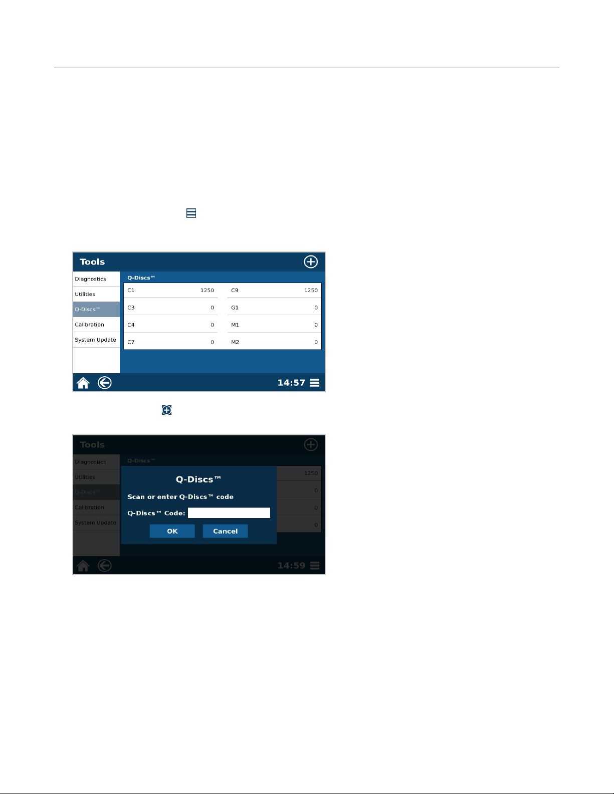
2. Select Tools.
3. Select “Q-Discs.”
4. Select the New icon .
5. Manually type in the barcode on the Q-Disc box or use barcode scanner from the accessory kit.
6. Select “OK” to add the Q-Discs to the database.
• If a valid code is entered then “successfully added...” will appear and the user will select “OK.”
• If an invalid code is entered, then try re-entering the code. The Q-Disc codes are case sensitive and contain
letters and numbers.
29Q-Discs
Page 34
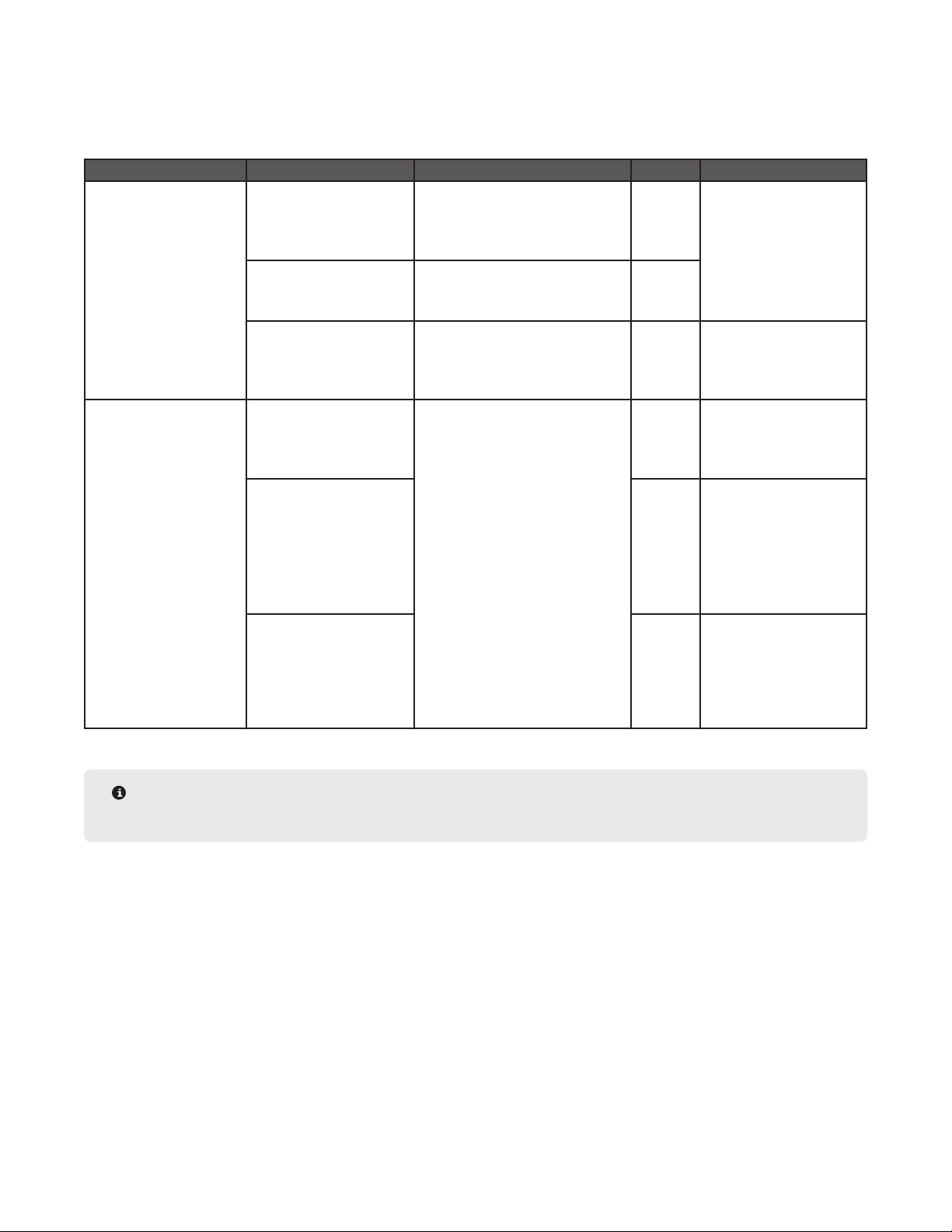
Q-Disc Comparison Guide
Select the appropriate Q-Disc for sample. Suggested sample types are listed below but are not the samples
applicable for each Q-Disc.
Analysis Type Suitable For Sample Types Q-Disc Caution
Gas Chromatography
or Gravimetric
Liquid
Chromatography
Dry samples Environmental samples including:
Solids & PUF lters
Total unbound fat food samples
Plastics
Wet or dry samples Wet, oily, or tar-like soil samples
Fine powder food samples that do
not drain with C1 or C3
Coarse samples (less than
270 mesh
Dry samples Pesticide residue in food
Wet or dry samples
Samples less than or equal
to 5 g
Wet samples
Samples more than 5 g
Use for samples that do not drain
with the other C line lters
applications
C1 or C3 Do not use if using water
for the extraction solvent
C4 or C7
C9 Do not use if using water
for the extraction solvent
Use as support disc for
M2
M1 Do not use if using water
for the extraction solvent
Do not use for wet
samples
M2 Always run with textured
side up in Q-Cup
Use C9 support below wet
samples
Do not heat above 100 °C
Only use with ACN,
alcohols, acetone, & H2O
G1 Always sandwich with C9
Q-Discs
NOTE
Q-Discs are listed in order of increasing porosity.
30 Q-Discs
Page 35
Methods
One Touch Methods are methods created and optimized by CEM for a variety of sample types to reduce the method
development time and effort required by the user. These methods cannot be edited, but they can be copied into
the User Methods folder, where the parameters can be edited.
User Methods are created by the user and can be edited at any time. These methods are typically for users with
unique or specialized products that do not obtain optimal results using a One Touch Method. User methods can be
imported and exported from another instrument.
Create Method
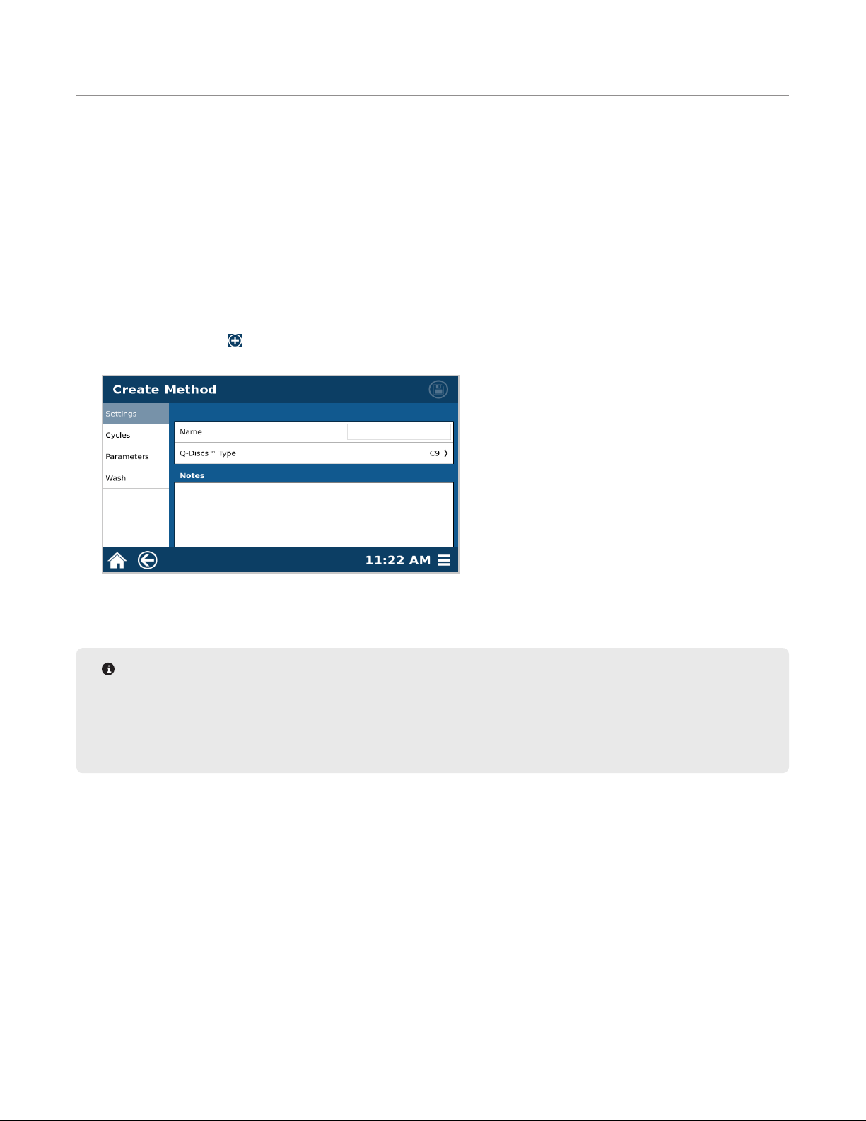
1. Select “User Methods” from the home screen.
2. Select the New icon in the top right corner of the screen.
3. Enter the appropriate “Settings”.
3.1. Enter a unique method name to easily link the method to the sample type being analyzed.
3.2. The preferred Q-Disc will auto ll. To change the Q-Disc, select “Q-Discs Type”.
NOTE
You will only be able to run the method if you have Q-Discs available. If you have not scanned them in yet,
do so now.
The preferred Q-Disc can be changed in the software Settings > Run > “Preferred Q-Discs”
3.3. Enter notes specic to method, such as sample type and sample size.
4. Select the “Parameters” tab and enter the appropriate parameters.
31Methods
Page 36
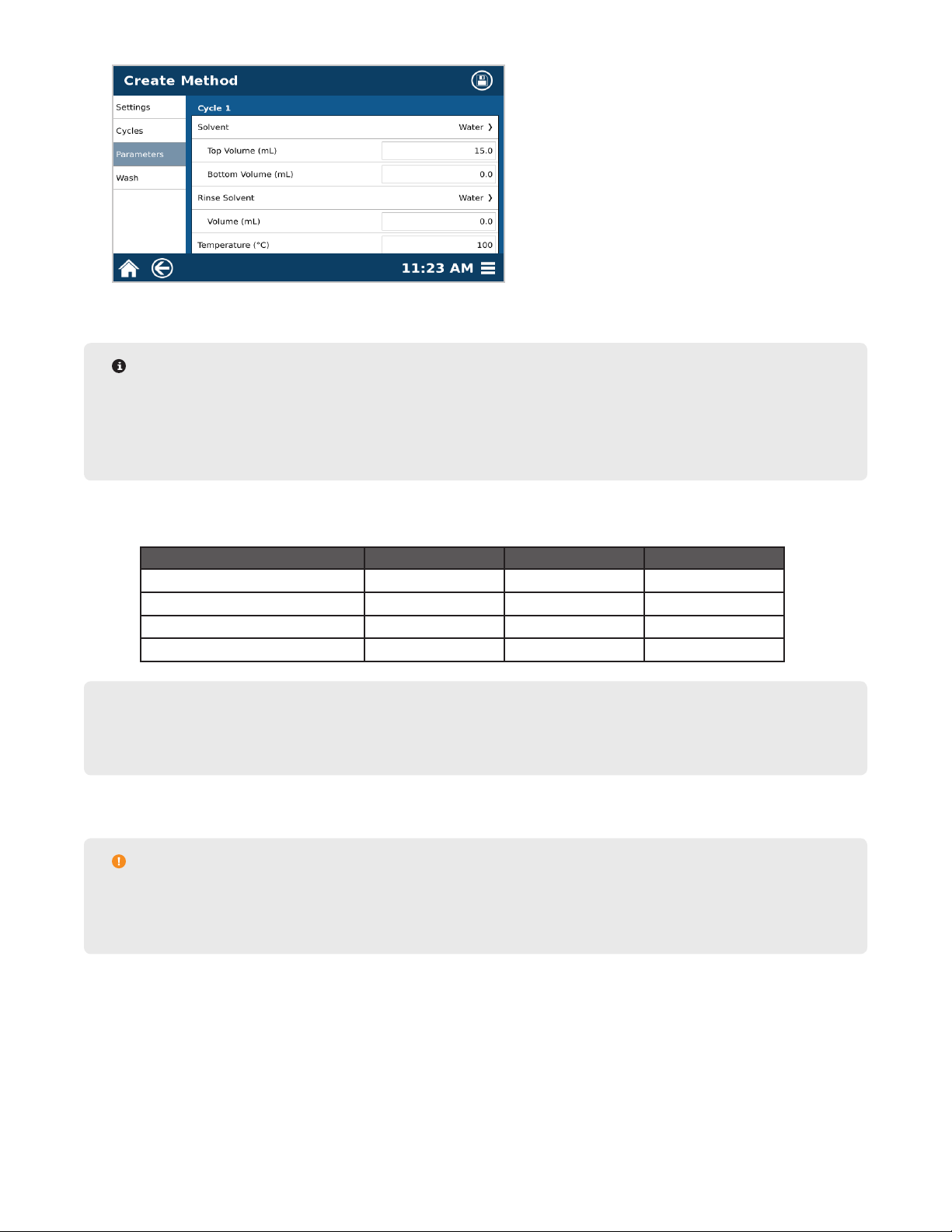
4.1. Select the desired solvent for the cycle and rinse.
NOTE
It is suggested that the extraction solvent and rinse solvents be the same. The selected solvent must be
assigned in “Bottle Setup.” If you attempt to save a method using a solvent that is not assigned in bottle
setup, a “Bottle Setup Missing Solvent” error will display. Refer to the “Bottle Setup & Conguration”
section in this manual to properly assign a solvent line.
4.2. Select the solvent volume for Top Volume, Bottom Volume, and Rinse Volume. The maximum volume for
one cycle is 40 mL.
EDGE Parameters Minimum (mL) Maximum (mL) Suggested Volume (mL)
Top Volume 5 40 10-20
Bottom Volume 0 10 0-10
Rinse Volume 0 35 5-10
Total Volume Per Cycle 5 40 15-40
NOTE
For larger sample sizes lling the Q-Cup, the bottom add may need to be eliminated and added to the top
add to ensure full saturation of solvent in sample.
4.3. Enter the desired temperature.
CAUTION
Maximum temperature will be solvent-dependent. The software will only allow safe running conditions.
For plastic samples, the set temperature must be below the melting point.
4.4. Scroll down and enter the desired Hold Time.
5. If applicable, add a second cycle. Multiple cycles may be necessary when analyte of interest is highly concen-
trated.
32 Methods
Page 37
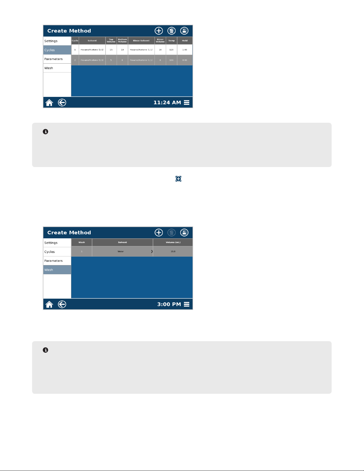
NOTE
If it is desired to run a two cycle method with 40 mL or less and collect both cycles separately, this can
be done in the settings tab. Toggle the ON/OFF switch to on. If this is not desired, the two cycles will be
collected in one vial if the total extraction volume is 40 mL or less.
5.1. Select the “Cycles” tab and then the New icon . The system will automatically populate the solvent volume so that the total solvent volume is 40 mL, which is the maximum volume that can be collected in one
vial.
5.2. To edit the cycle, highlight the cycle.
5.3. Repeat all of step 4 to enter the Parameters.
6. Select the “Wash” Tab.
6.1. Select highlighted area beneath “Solvent” to display the solvent menu.
6.2. Select the solvent that was used for the extraction.
NOTE
Water is recommended if salt is used during extraction or sample contains salt. If this is the case, a
second wash cycle of the extraction solvent is recommended.
DCM is recommended for environmental samples. If this is the case, a second wash cycle of the extraction
solvent is recommended
6.3. Select highlighted area under “Volume (mL)” to change the volume using the keypad. The recommended
volume is 10-30 mL.
6.4. If applicable, add additional wash cycles by repeating the steps above.
33Methods
Page 38
7. Select the Save icon at the top right of the screen to save any changes.
CAUTION
Observe the entire extraction process when establishing a procedure for the rst time to ensure proper
system functionality.
Edit Method
1. Select the method to be edited.
2. Select the Edit icon at the top of the screen.
3. Select desired tab to edit (settings, cycles, parameters, or wash).
4. Edit parameters.
NOTE
See “Create Method” for specic details regarding method/wash parameters and cycles.
5. Select the Save icon .
Copy Method
NOTE
A One Touch or User Method can be copied. If a One Touch Method is copied, it will be transferred into the
User Methods folder.
1. Select the method to be copied, and select the Copy icon .
2. Create a new name for the method; after “OK” is selected, the method will be transferred into the User Meth-
ods folder and the “Edit Method” screen will appear.
3. Edit the desired parameters, and save method.
Delete Method
1. Select method to be deleted.
NOTE
Multiple methods can be deleted at a time by highlighting multiple methods.
2. Select Delete icon .
3. Select “OK” to delete the method(s) or “Cancel” to return to the previous screen.
34 Methods
Page 39
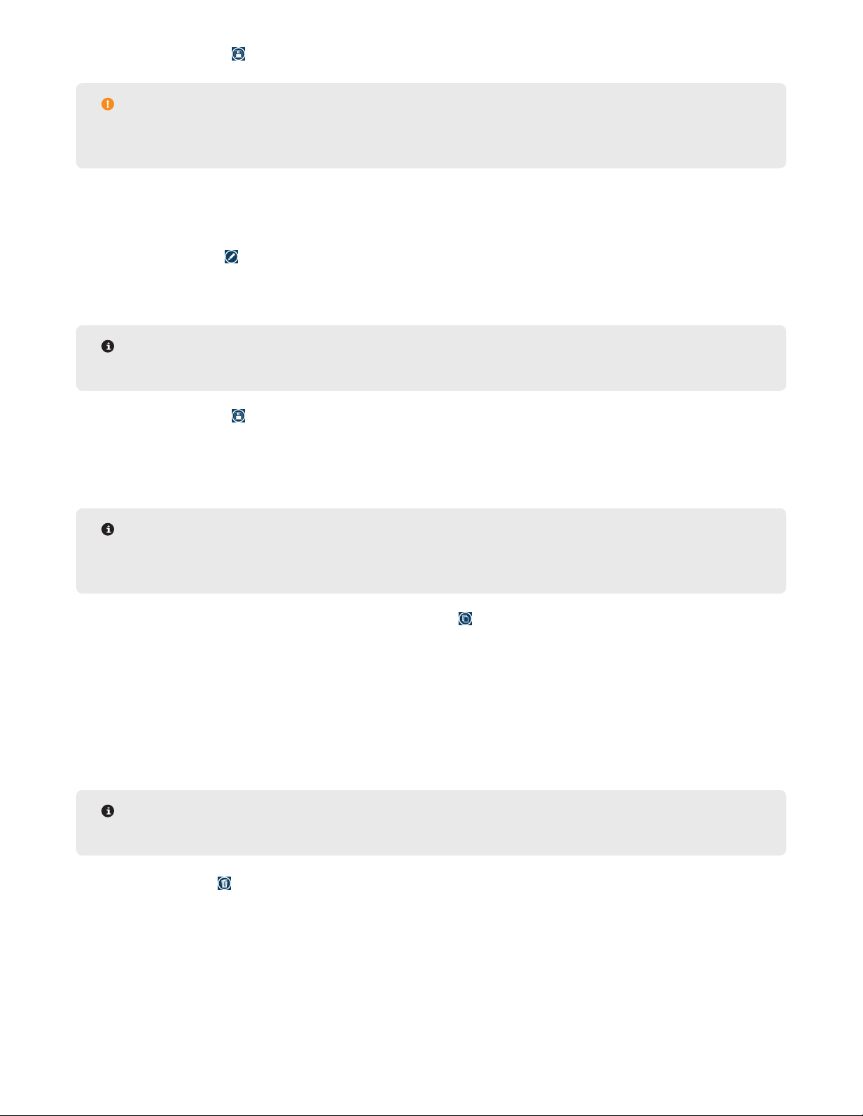
Export Method
NOTE
There must be a ash drive inserted into the USB port to export a method.
1. From the methods screen, select the method(s) to export to the ash drive.
2. Select the Export icon .
3. Select the destination.
4. Select “OK” to Export the method(s) or “Cancel” to return to the previous screen.
5. Select “OK” when nished.
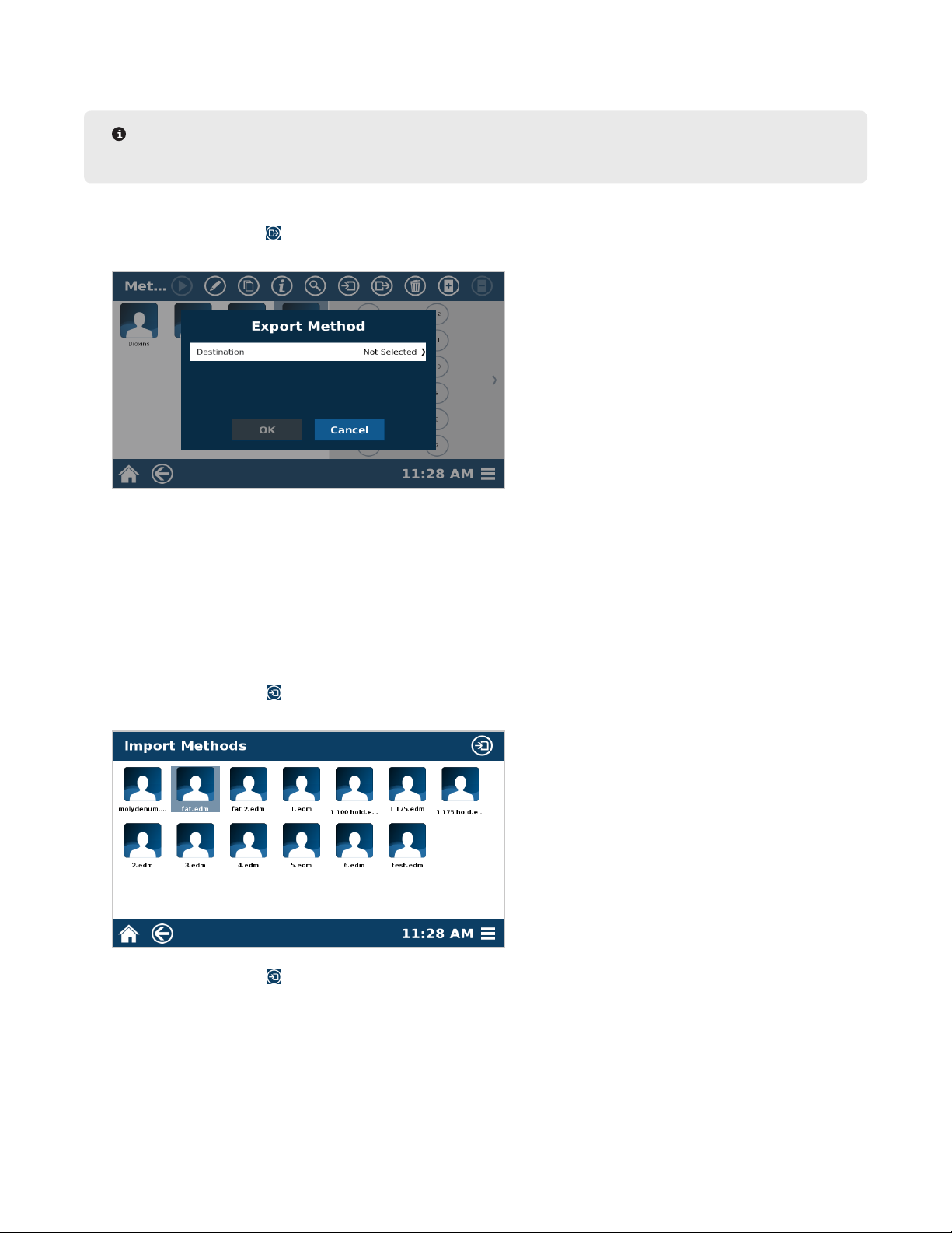
Import Method
Only Administrators can import methods.
1. To import a method, insert a ash drive in the USB port on the left side of the system.
2. Go to the Methods screen.
3. Select the Import icon .
4. Select the method(s) to import from the ash drive.
5. Select the Import icon .
6. Select “OK” once nished.
35Methods
Page 40
Users
Only Administrators can create, edit, or delete users. A Basic (non-Administrator) user can only edit their password.
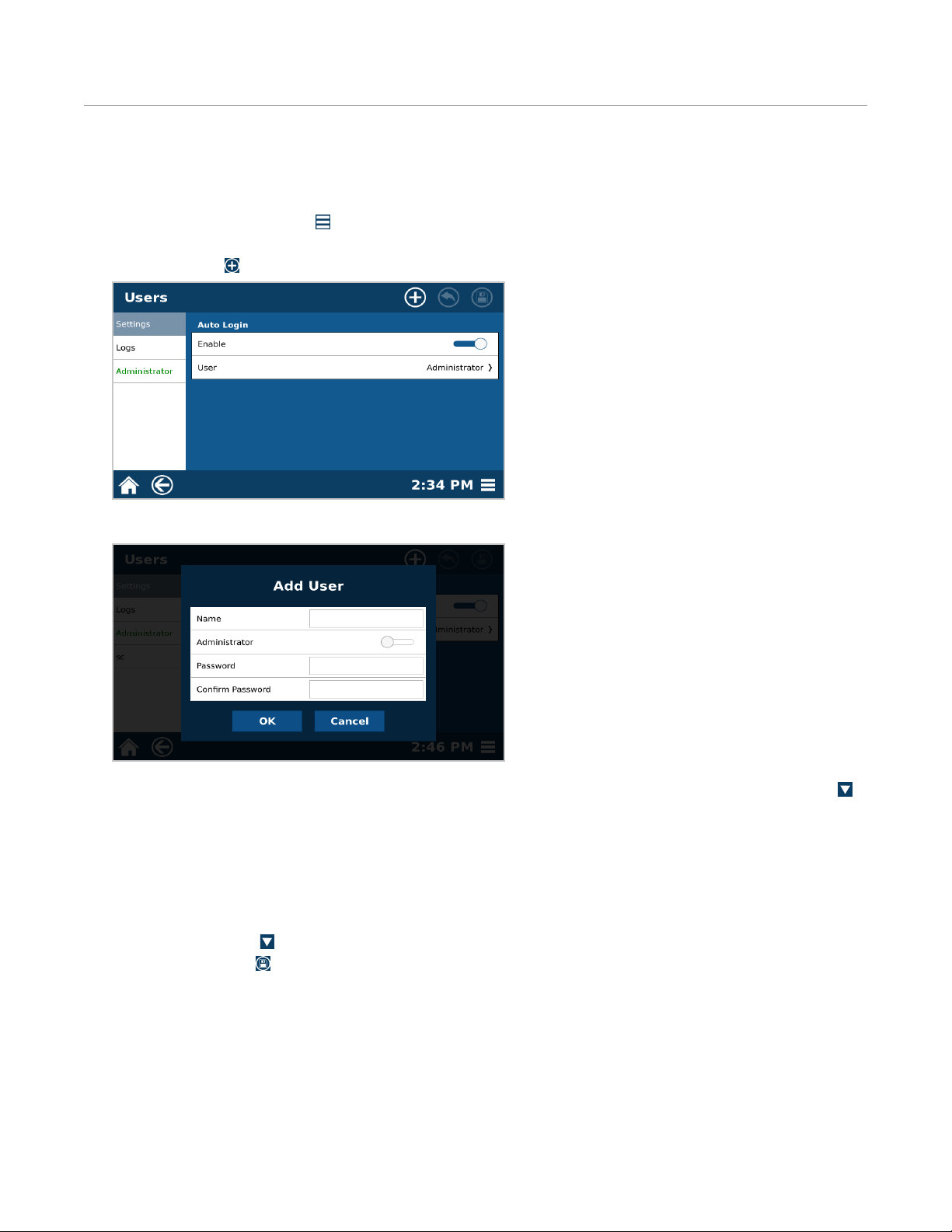
Create User
1. Select the System Menu icon in the bottom right corner of the screen.
2. Select Users.
3. Select New icon .
4. Select Name.
5. Using the keypad, enter the desired name using a maximum of 16 characters. Press the Hide Keypad icon
on the bottom right of the keypad to return to the Add User screen.
6. Assign the user as an administrator or non-administrator (basic). If toggled on, the user has full Administrator
access and is able to create and edit methods and make system setting changes. If toggled off, the user only
has Basic access, which is capable of choosing different methods and running samples only. While there may
be multiple Administrator and Basic users, every system must maintain at least one Administrator.
7. Using the keypad, enter the desired password. Once the password is entered, conrm the password. Select
the Hide Keypad icon to return to the Add User screen.
8. Select the Save icon to save all user information in the instrument software.
9. The software will indicate that an additional user has been entered into the database.
10. Select “OK.” All users are listed beneath the “Add User” tab. Additional users can be added at this time.
36 Users
Page 41

Edit/Delete User
1. Select the System Menu icon in the bottom right corner of the screen.
2. Select Users.
3. Select the user to edit/delete.
4. Select the Edit icon or Delete icon .
• If Edit is selected, make the appropriate changes, and select the Save icon .
• If Delete is selected, conrm that the user wishes to delete the selected user.
Auto Login
1. Select Users.
2. “Auto Login” can be toggled on and off.
• If Auto Login is set to “OFF”, the operator will have to choose a user and login each time the system is
turned on.
• If Auto Login is set to “ON”, the Home Screen will be displayed once the EDGE completes the initial
powering.
Logs
The User Logs is an account of user activity including method import/export, methods run, user login/logout, and
edit/delete users.
There is not a limit to how many methods/results that can be stored per user.
37Users
Page 42

Data Management
Export Data
Data including sample information, date/time and run data can be exported onto a ash drive.
1. Insert ash drive (USB) in the USB port of the EDGE.
2. Select the method to export data from.
3. Select the Info icon .
4. The method will be shown. Select a Sample ID to export from.
NOTE
If a method is edited, data prior to edit is no longer available. Only User Methods can be edited.
5. The run data can be observed in this screen. Touch and move the blue line to see temperature/pressure at
different times.
38 Data Management
Page 43

6. Select the Export icon .
7. Select Destination.
8. Select “OK.”
Search Data
1. From the methods screen, select the “search” icon .
2. Data can be ltered by method name, date, time, and number of samples. Toggle each of these to search for
specic samples.
39Data Management
Page 44

3. Once lters are set up, select the Search icon and “Results” tab.
40 Data Management
Page 45

Calibrations
Verify Waste Calibration
The waste position requires calibration verication during the initial install, if the EDGE system is moved, and semiannually.
WARNING
Never place hands into the vessel chamber area when the EDGE is in use or powered on.
1. Select the System Menu icon in the bottom right corner of the screen.
2. Select Tools.
3. Select the Diagnostics tab and view the “Actuator” section.
4. Select “Close.”
5. A warning will appear. Select “OK” once chamber is clear.
6. Scroll down to the Autosampler section. Select “Waste.” The autosampler dispense needle will travel to the
waste position.
41Calibrations
Page 46

NOTE
Pay attention to the dispense needle during this time; it should enter into the waste port smoothly. If it
doesn’t, the waste position will need to be recalibrated.
6.1. Select “Home.” The autosampler will travel to the home position.
6.2. Scroll upward to the Actuator section.
6.3. Select “Open.”
NOTE
If the autosampler crashes or movement is not smooth at any point during the verication, the
autosampler will need to be calibrated. Please see “Autosampler Calibration.”
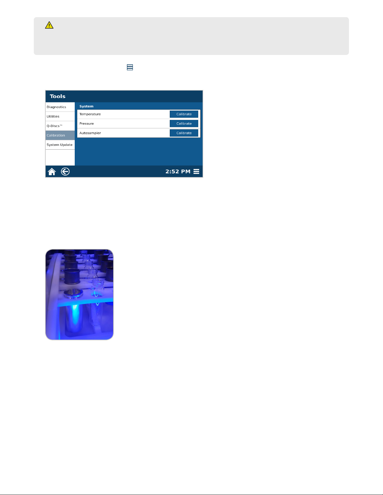
Pressure Calibration
The pressure requires calibration during initial install, if the EDGE system is moved, and semi-annually.
1. Select the System Menu icon in the bottom right corner of the screen.
2. Select Tools.
3. Select Calibration.
42 Calibrations
Page 47

4. Select Pressure “Calibrate.” This will take less than a minute.
5. Select “OK.”
Verify Autosampler Calibration
The autosampler requires calibration verication during the initial install, if the EDGE system is moved, and semiannually.
1. Select the System Menu icon in the bottom right corner of the screen.
2. Select Tools.
3. Scroll down to the bottom of the page to the Autosampler section.
CAUTION
When verifying the autosampler calibration, always select “Load,” “Collect”, and “Unload” in that order
without skipping a function.
4. Place a Q-Cup and collection vial in position 4 of the rack.
NOTE
Position 4 is used to verify the calibration. Moving the Q-Cup to and from this location veries the
interpolation of the calibration positions and is therefore the best test for the calibration.
5. Select “1” from Sample Position to display the sample position menu, and select position 4.
43Calibrations
Page 48
6. Select “OK.”
7. Select “Load.” The autosampler will load the Q-Cup into the vessel chamber.
NOTE
Pay attention to the Q-Cup during this time; the loading process should be very smooth.
8. Select “Collect.” The dispense needle on the autosampler will move to the collection vial in position 4 of the
rack.
9. Select “Unload.” The autosampler will unload the Q-Cup from the vessel chamber and place it back into position 4 of the rack.
NOTE
If the autosampler crashes at any point during the verication, the autosampler will need to be calibrated.
Please see “Autosampler Calibration.”
Autosampler Calibration
The Autosampler may require adjustment if movement is not smooth. For detailed instruction on calibrating the
autosampler, please see the “Autosampler Calibration” video located in the System Menu or follow the instruction
below.
There are 3 coordinates for the Autosampler: X, Y, and Z.
• X: Moves the autosampler fork right and left
• Y: Moves the autosampler forward and back
• Z: Moves the autosampler arm up and down
There are three settings for each coordinate: Coarse, Fine, and Ultrane.
• Coarse: Moves the autosampler a large distance
• Fine: Moves the autosampler a moderate distance
• Ultrane: Moves the autosampler tool a short distance
There will be 3 selections along the top of the screen: Back, Estimate, Skip.
• Back: Will home autosampler (if not already home) and go to the previous position; ie. position 7->1
• Estimate: Takes the autosampler to an estimated position based on the position that is currently being
calibrated. Once austosampler moves, Home will appear.
• Skip: Skips a position if a position is not in need of calibration
44 Calibrations
Page 49
WARNING
NEVER place hands or any object into the automation area from the time “Start” is selected until the
system is idle.
1. Select the System Menu icon in the bottom right corner of the screen.
2. Select Tools.
3. Select Calibration.
4. Select Autosampler “Calibrate.”
5. Select the tool that will be used for calibration: Q-Cup or Calibration Tool.
• If calibration tool is available, select the image of the calibration tool.
• If the calibration tool is not available, use a Q-Cup.
6. Select “OK” to begin calibration process.
7. Follow the prompts on the screen to begin calibration, and select “OK.”
8. If using the tool, place the bottom of the tool in position 1 of the autosampler rack.
9. Place the top of the calibration tool or the Q-Cup on the top of the autosampler fork. Make sure the top lip is
sitting ush on the autosampler fork.
45Calibrations
Page 50
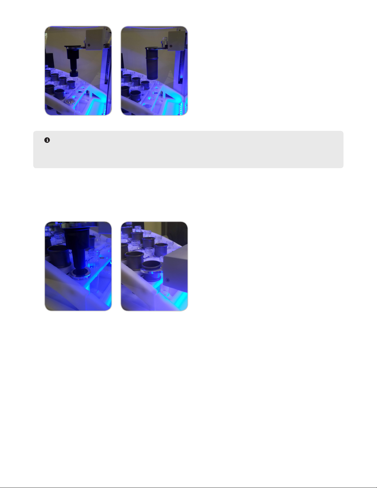
NOTE
If the tool crashes at any point, leave the system alone until it nishes moving, select “Home,” and restart
calibration.
10. Select “Estimate.” The system will move the autosampler fork to an approximate location over to the position
being calibrated.
11. Use the arrows and settings to adjust the tool or Q-Cup. The “OK” button will be grayed out until the tool is
within the specied range.
12. Once in the specied range and the tools are ush or autosampler fork sits below Q-Cup lip, select “OK.”
13. You will then calibrate positions 7 and 12 the same way.
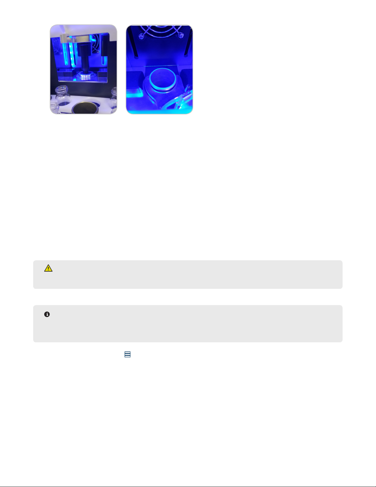
14. Calibrate the drop off position.
• If using the calibration tool, place the bottom piece of the tool in the chamber.
15. Press estimate, and follow the same alignment procedure as before.
• If using the tool, the top piece of the tool should glide into the bottom piece without hitting the sides of the
tool. If the top piece of the tool moves as you are moving the Z-axis, the Y and Z coordinates are not properly
aligned. Once the system is nished moving, select “Home,” ensure that the top piece is sitting on the fork
correctly, select “Estimate,” and try again.
46 Calibrations
Page 51
Once the tool/Q-Cup looks aligned, select “Coarse,” and then select the Z-axis “up” arrow once and then
down once. The tool/cup should move freely without hitting any sides. If this is not a smooth transition, retry
calibrating the drop-off position before pressing ok.
16. Once the position is calibrated, press “OK” to proceed to the next step.
17. Remove the tool/cup from the system before calibrating the waste position; No tool/Q-Cup is used for calibrat-
ing the waste.
18. Select “Estimate.”
19. Move the autosampler using “Fine” and “Ultrane” in small increments only. Move the autosampler until the
needle is at least ¾ into the waste port.
20. Select “OK” to save calibration values.
Temperature Calibration
This should be performed yearly by a CEM Service Engineer. Contact CEM Corporation before calibrating
temperature.
WARNING
Do not place hands or objects in the actuator (vessel chamber) area unless instructed to do so.
NOTE
Before starting, water should be plumbed into one of the solvent lines. A thermometer will be needed to
record the temperature during calibration.
1. Select the System Menu icon in the bottom right corner of the screen.
2. Select Tools.
3. Select Calibration.
47Calibrations
Page 52

4. Select Temperature “Calibrate.”
5. Select “OK” to begin temperature calibration. The actuator will close, the dispense needle will travel to waste
and the system will begin lling the chamber with water. Follow the remaining software prompts to complete
the calibration.
5.1. After 4:00 min, you will be prompted to take the temperature of the water; be sure to mix the water.
5.2. After 0:20 seconds of mixing, the software will prompt you to type in the nal temperature you are reading.
Type in the value, and select “OK.”
5.3. Verify temperature reading, and select “OK.” The system will begin ushing the water into waste and will
then return to the home position.
6. Once calibration is complete select “OK.”
48 Calibrations
Page 53

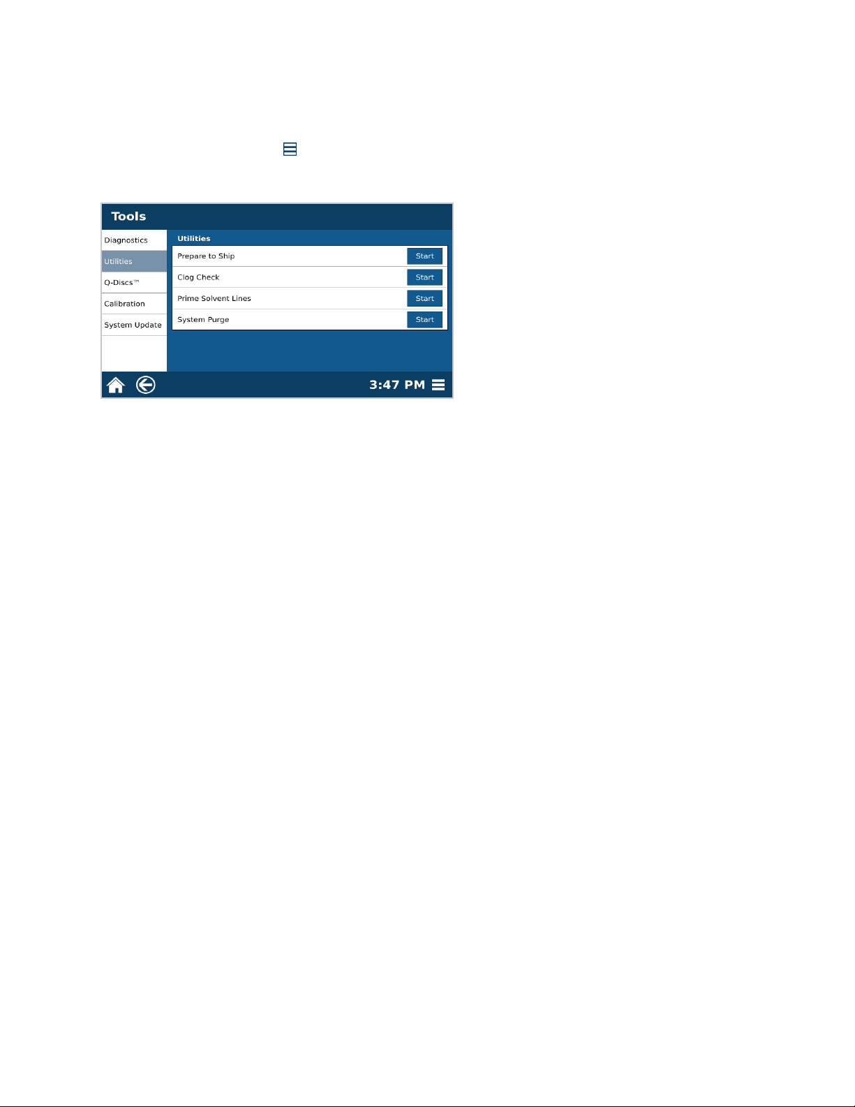
Utilities
Prime Solvent Lines
Solvent bottle lines may need to be primed if the EDGE has been idle for an extended period of time or if bottles
have run dry.
1. Select the System Menu icon in the bottom right corner of the screen.
2. Select Tools.
3. Select Utilities.
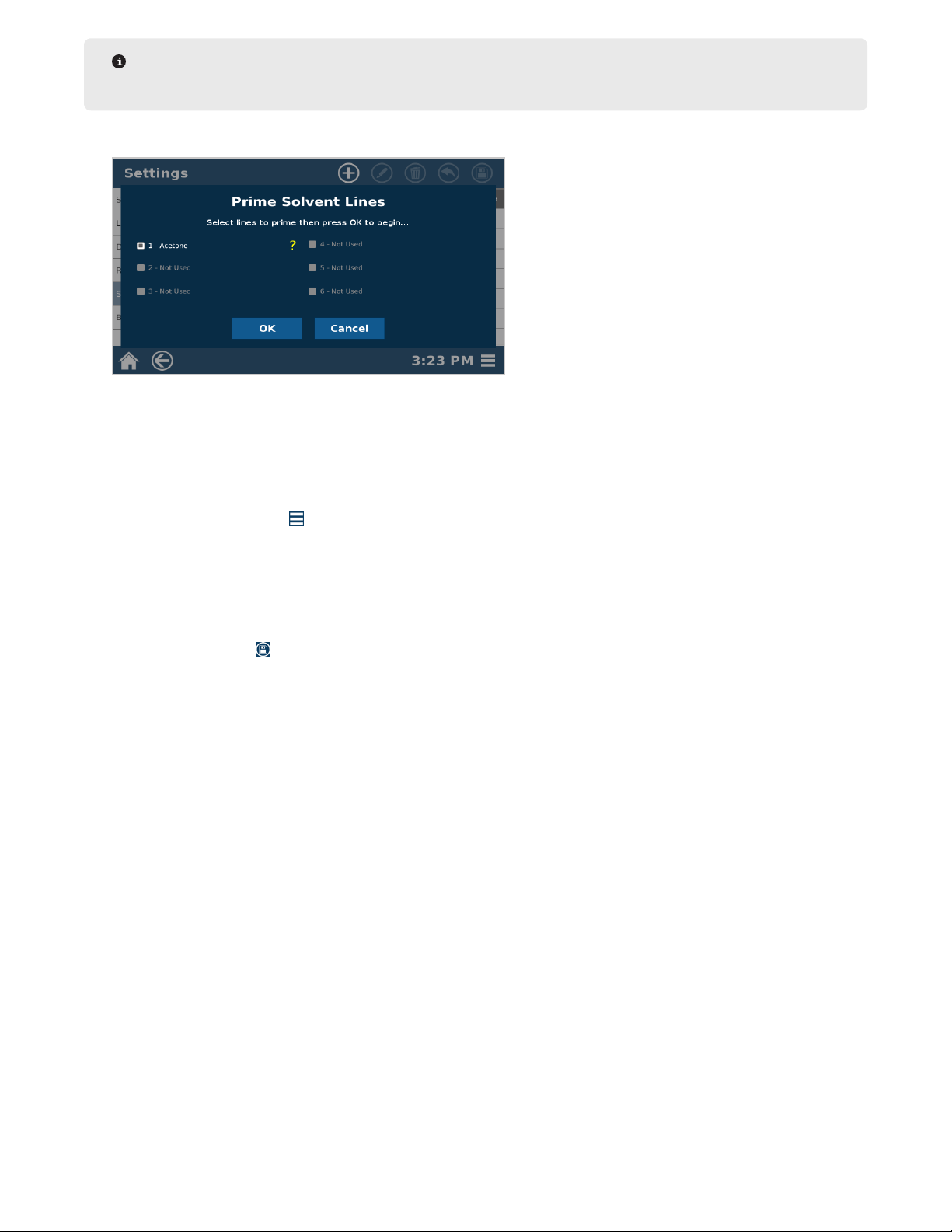
4. Select “Prime Solvent Lines.”
5. Select the solvent lines you would like to prime, and select “OK.”
NOTE
The only lines that are available to prime will be the ones setup in bottle setup. If you wish to prime more
lines, they must rst be assigned in bottle setup.
6. Once complete and a green check mark is shown, select “Close.”
NOTE
If a green check mark is not shown, there is a possible leak in the solvent line. Please contact CEM
Corporation.
49Utilities
Page 54
System Purge
System purge will dispense solvent in the chamber into the waste bottle. The system purge option only needs to
be utilized if power is lost during a run or to determine system back pressure. System back pressure should be
between 7.0 - 9.5 psi.
1. Select the System Menu icon in the bottom right corner of the screen.
2. Select Tools.
3. Select Utilities.
4. Select “System Purge.”
5. Select “OK” to begin purge. The actuator will close, the dispense needle will go to the waste position, and the
pump will purge the system into the waste bottle.
6. Select “OK” when purge is complete.
50 Utilities
Page 55
Software Update
The current version of EDGE software can be found on the CEM website. Please register the EDGE Serial Number
and create an account to access software updated.
How to Update Software
1. Download the EDGE software and copy onto USB stick.
2. Insert USB Stick containing the software update bundle (*.cib) into the EDGE USB port.
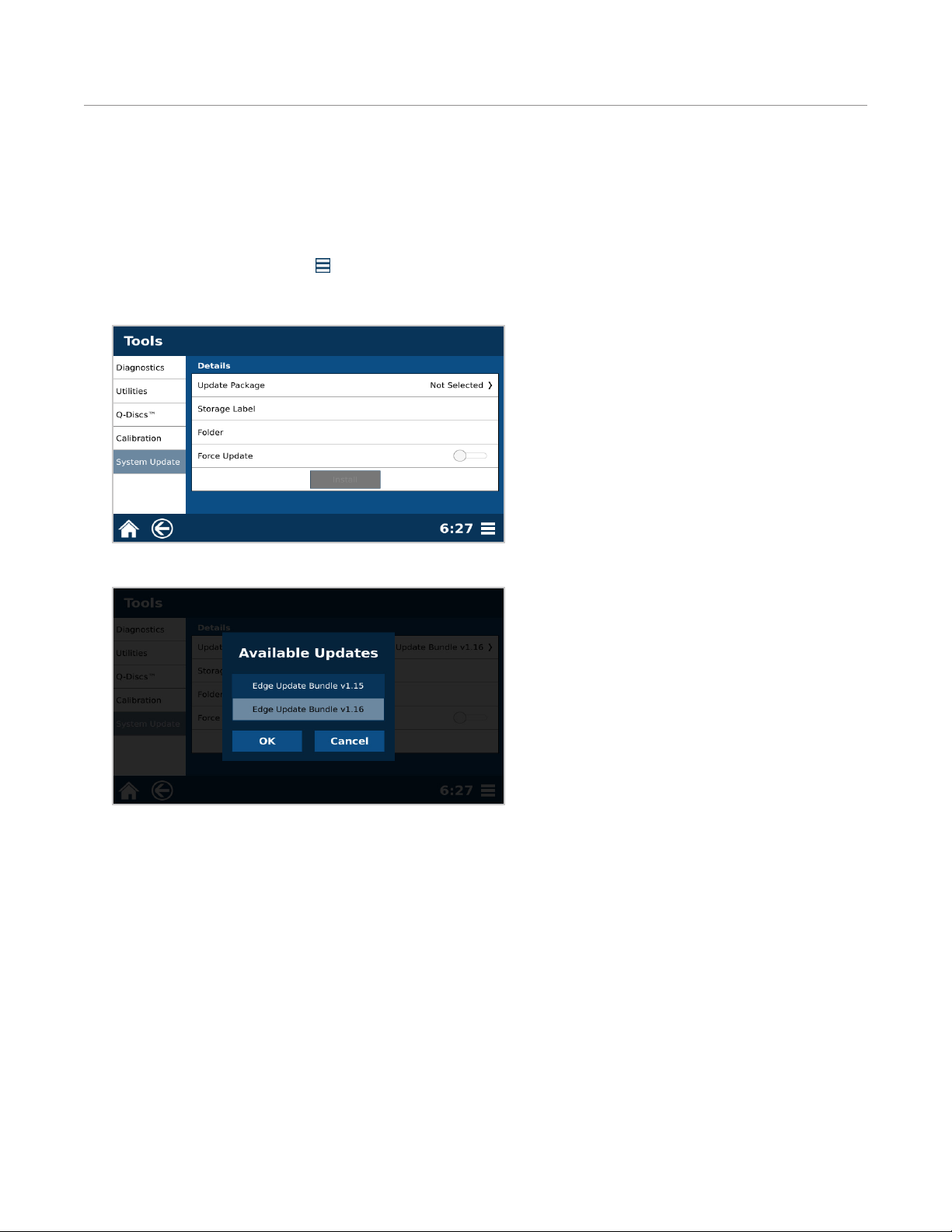
1. Select the System Menu icon in the bottom right corner of the screen.
2. Select Tools.
3. Select “System Update.”
4. Select “Update Package.”
5. Select the software version and select “OK”.
6. Toggle the “Force Update” to on.
7. Select “Install.” “Preparing Update...” will be shown on the screen and the system will automatically restart.
51Software Update
Page 56
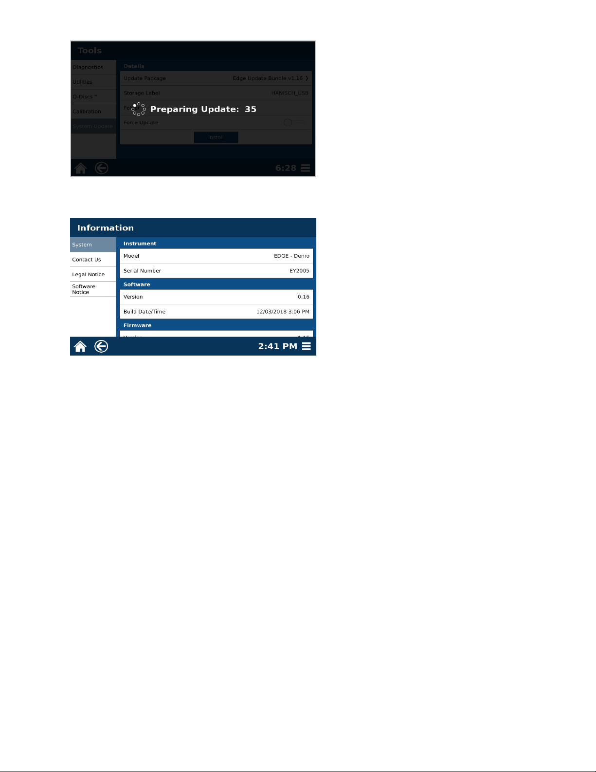
8. Upon restart, the system will automatically initiate the software update process.
9. To verify the software version, select the “System Menu” > “Information” > “System Information.”
52 Software Update
Page 57

System Repacking
Prepare to Ship
Follow procedures below to prepare the EDGE for shipment. If shipping brackets are not available, please contact
CEM Corporation.
1. Remove the rack from the EDGE platform.
CAUTION
Never ship unit with rack in position.
2. Select the System Menu icon located in the lower right corner of the screen.
3. Select Tools.
4. Select Utilities.
5. Select Prepare to Ship “Start.”
6. Follow prompts on the software screen to prime lines with water, ush chamber, dry lines, and add shipping
brackets. If shipping brackets are not available, please contact CEM Corporation.
CAUTION
Solvent lines must be purged prior to packing or shipping instrument.
7. Select “OK.”
8. Follow the directions on the screen to align with the shipping brackets.
NOTE
Screws should be installed on the instrument already. Shipping brackets should be with the shipping boxes
the system was delivered in. Remove appropriate screws, place bracket in position and re-install screws.
9. Once shipping brackets are installed, turn the EDGE off using the power switch located on the left side of the
unit.
10. Disconnect the power cord from the EDGE and power receptacle.
11. Ensure all bottles and waste lines have been removed.
53System Repacking
Page 58

CAUTION
Never ship unit with waste lines or bottles in position.
12. Refer to the Packaging guide for the remaining steps to box the EDGE system.
54 System Repacking
Page 59
Routine Maintenance
CEM suggests that you perform the routine maintenance on your EDGE as outlined below, along with having a CEM
Certied Technician to come check out your system once a year.
Daily
• Ensure exhaust hose is attached
• Ensure clear safety enclosure is in place
• Check solvent bottle
• Check waste bottle
• Clean up spills with a clean soft cloth
• Inspect Q-Cups. Discard Q-cup’s that are not round or have dents.
Monthly
• Check your consumable supplies to prevent early depletion. Q-Cups and Q-Discs must be purchased directly from
CEM Corporation or through it’s authorized dealer network.
WARNING
Ensure that system is idle, the power switch is positioned to off, and system is disconnected from the
power supply prior to cleaning.
CAUTION
Only use water and a soft cloth to clean the system. Using other cleaning solutions, brushes, and
materials can cause damage to the device.
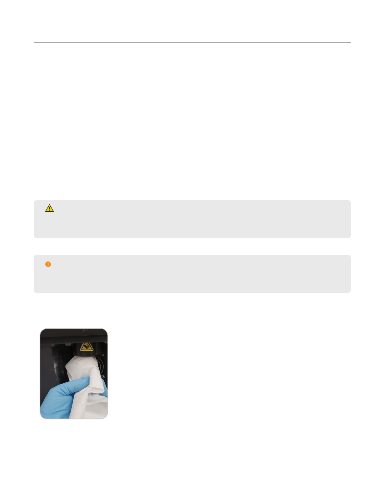
• Clean the clear safety enclosure with a soft cloth dampened with water.
• Remove rack and wipe down EDGE surfaces and rack with a soft cloth dampened with water.
• Clean Actuator O-rings using a soft cloth dampened with water.
55Routine Maintenance
Page 60

Annually
• Preventative Maintenance by CEM Certied Technician
This is performed by a CEM Certied Technician, once per year. However, should your individual requirements vary,
a CEM Representative is available to assist in creating a schedule to meet your needs. Contact the CEM Contract
Administrator at 800-726-3331 for assistance.
56 Routine Maintenance
Page 61

Troubleshooting
Problems and Possible Solutions
Problems Possible Cause Possible Solutions
Recoveries are low Hold time not long enough Increase hold time by 1:00
Incorrect Temperature Increase temperature by 10 °C or decrease by 10 °C for
temperature sensitive analytes
Water in the extract Wet Sample Increase drying agent
Possible System Clog Slow sample draining Increase pore size of Q-Disc. For cellulose, increase C#
Mix dry samples with sand to disperse sample
Q-Cup(s) overlled Clean the actuator. See “Routine Maintenance” for instructions. See
“Sample Preparation” for preventative measures.
Solvent/Extract Recovery low Solvent Bottle(s) empty Add solvent
Slow sample draining Increase pore size of Q-Disc. For cellulose, increase C#.
Mix dry samples with sand to disperse sample
Particulates in extract Porosity of samples less than
Q-Disc
Q-Cup sticking to actuator Q-Cup(s) dirty Clean the Q-Cups. See “ for instruction
Q-Cup(s) overlled Clean the actuator. See “Routine Maintenance” for instructions. See
Max Pressure Exceeded Pressure generated at
temperature exceeds maximum
system pressure
Decrease pore size of Q-disc. For cellulose, decrease C#
“Sample Preparation” for preventative measures
Decrease method temperature or decrease amount of sample
Clog Check
1. Select System Menu icon located in the lower right corner of the screen.
2. Select Tools.
3. Select Utilities.
4. Select Clog Check Start.
5. A screen will appear with a list of locations to check for a clog: Vent, Drain, Cooling coil/dispense needle.
Select “OK” to begin clog check.
57Troubleshooting
Page 62

6. If green checks appear beside vent, drain, and cooling coil/dispense needle, then clog check has completed
successfully. Select “OK.” If a red “x” appears, proceed with next step.
6.1. If red “X” appears, check inside chamber and dispense needle for any obstruction to solvent ow such as
sample in chamber or needle.
WARNING
Never place hands into the vessel chamber area when the EDGE is in use or powered on.
NOTE
If Clog Check fails, the EDGE must be powered off/on before Water Wash can be attempted/loaded.
7. Select and run “Water Wash” Method to clear clog.
7.1. If “Water Wash” Method is not available, create a User method with the following parameters: Solvent=Wa-
ter; Top Volume=30mL; Bottom Volume=0mL; Rinse Volume=0mL; Temperature=150°C; Hold time=3:00;
Wash=10mL Water.
7.2. Place empty Q-Cup, without Q-Disc in place, and collection container on the rack.
7.3. Load the “Water Wash” method.
7.4. Select the Run icon at the top of the screen and select “Start.”
8. If there is a clog, contact CEM Corporation if system continues to fail clog check and “Water Wash” procedure
has been performed more than once.
58 Troubleshooting
Page 63

Clog Recovery
A clog can occur during the collection or purging of an extraction. In either case, if the system senses too much
back pressure, you will be directed to remove the Q-Cup.
WARNING
The Q-Cup may still be hot, and there may be solvent in the Q-Cup. Be cautious when removing.
Always remove the Q-Cup before selecting “OK.”
The system will then purge into the collection vial to determine if there is a system clog. If the system purges
without any back pressure, the system will nish the run like normal (wash and return home). If this is not the
case, this means that there is something wrong with how the sample was prepared, either Q-Disc choice or sample
choice. Refer to documents or call (800) 726-3331 (inside the US) or (704) 821-7015 and ask for “Molecular
Support”, or email CEM EDGE applications support at molecular.support@cem.com.
If the system does detect back pressure, there is a system clog. Refer to the clog bulletin, or call your local CEM
Service Technician for assistance.
Exhaust Fan Inoperable
WARNING
The exhaust hose must be connected and draw at least 30.5 CFM at the point of connection at all times
as it is essential for removing harmful gases away from the EDGE instrument. Vapors should be vented
into a fume hood by means of the exhaust hose only.
Upon pressing “Start” if the “Exhaust Fan” message appears, select “Cancel” and contact the CEM Service
Department (inside the US1-800-226-5228) or the nearest subsidiary or distributor (listed on www.cem.com/
contact.html) to request service information.
CEM advises not running the EDGE system if exhaust fan is inoperable. If “OK” is selected, the user acknowledges
the exhaust fan is inoperable but would like to continue running the samples.
59Troubleshooting
Page 64

System Specifications
Location Requirements
• Has adequate ventilation that can be accessed via the exhaust hose (no further than 10’ away) to remove fumes
from system
• Provides adequate space for sample handling
• Has a dedicated, grounded outlet no more than 5 ft (1.5 m) from unit
• Is free from vibration of large equipment
• Provides clear visual access to the display of the system
• The system weighs 70 lbs (31.75 kg) without rack or vessels
• Instrument Dimensions: 14.25” (37 cm) W x 25.53” (65 cm) D x 27.93” (71 cm) H
• Recommended counter space: 45” (115 cm) W x 30” (77 cm) D x 28” (71 cm) H
• The above provides 12” (31 cm) of open space on the right side of the system so that the racks can be
easily loaded and 18.75” (48 cm) on the left side of the system for sample preparation and access to the
power switch
• Do not position the EDGE so it is difcult to access the power switch
Electrical Requirements
• Region Specic
• 100 - 120 VAC, 50/60 Hz, 10 A
or
• 200 - 240 VAC, 50/60 Hz, 5 A
• Line voltage must not vary more than 10% of its specied level
• Dedicated, grounded outlet
• Instrument is supplied with a power cord or an adequately rated power cord may be used
• Fuses:
• 100 - 120 VAC: 250 V, 10A 5 mm x 20 mm, fast acting
or
• 200 - 240 VAC: 250V, 5 A, 5 mm x 20 mm, fast acting
Environmental Requirements
• Indoor use only
• Altitude up to 2000 m
• Operating Temperature range of 50°F (10°C) to 85°F (29.4°C)
• A fume hood within 10 feet of unit or adequate exhaust that pulls a minimum of 30.5 CFM at point of connection
• Instrument is supplied with a ten foot long exhaust hose with a 2” ID
• Relative humidity range of 10 % to 85%, non-condensing
• Overvoltage Category II
• Pollution degree 2
60 System Specications
Page 65

Warranty
Limited Warranty Information
What Is Covered:
CEM Corporation warrants that the instrument will be free of any defect in parts or workmanship and will, at its
option, replace or repair any defective part (excluding consumables) or instrument.
For How Long:
This warranty remains in effect for 365 days from date of delivery to the original purchaser.
What Is Not Covered:
This warranty does not cover parts or workmanship damaged due to:
• Neglect, abuse or misuse,
• Damage caused by or to test samples,
• Damage incurred during instrument relocation,
• Damage caused by or to any attached equipment,
• Use of incorrect line voltages or fuses,
• Fire, ood, “acts of God” or other contingencies beyond the control of CEM Corporation,
• Improper or unauthorized repair, or
• Any other damage caused by purchaser or its agents.
Responsibilities of Purchaser:
To ensure warranty coverage, the purchaser must:
• Use the instrument according to directions,
• Connect the instrument properly to a power supply of proper voltage,
• Replace blown fuses,
• Replace consumables and
• Clean the instrument as required.
How to Get Service:
Purchaser should contact the Service Department of CEM Corporation or the nearest CEM subsidiary or distributor
for return authorization and for proper crating and shipping instructions to return instrument, freight prepaid, for
service. On-site repairs by an authorized service technician are available through the CEM Service Department.
Travel costs will be charged to the purchaser for on-site repairs.
Within the U.S. Outside the U.S.
CEM Corporation CEM Corporation
3100 Smith Farm Rd. 3100 Smith Farm Rd.
Matthews, NC 28105-5044 Matthews, NC 28105-5044
(800) 726-5551 (704) 821-7015
Fax: (704) 821-4368 Fax: (704) 821-4368
61Warranty
Page 66

Warranty Disclaimer:
CEM Corporation hereby excludes and disclaims any warranty of merchantability or tness for any particular
purpose. No warranty, express or implied, extends beyond the face hereof. CEM Corporation shall not be liable
for loss of use of instrument or other incidental or consequential costs, expenses or damages incurred by the
purchaser or any other user. This warranty is not transferable.
Purchaser’s Rights under State Law:
This warranty gives the purchaser specic legal rights, and the purchaser may also have other rights that vary from
state to state.
62 Warranty
Page 67

Technical Assistance
Applications Support
For the latest EDGE™ applications information, go to http://cem.com/edge/. The EDGE pages contain
downloadable applications notes, a listing of recent posters, method notes and more. A registered account is
required for download. CEM is proud to provide applications support for any solvent extraction related questions
from a team of trained chemists with a complete extractions lab. For applications support, call (800) 726-3331
(inside the US) or (704) 821-7015 and ask for “Molecular Support”, or email CEM EDGE applications support at
molecular.support@cem.com.
Technical Support
CEM is proud to provide technical support for the EDGE from a team of specially trained Service
Technicians. For technical support in the US and Canada, call (800) 726-5551 or (704) 821-7015 and ask for
“EDGE Service” or email service@cem.com. For technical support outside the US and Canada, contact your local
CEM Subsidiary or Distributor.
Requested Information
When contacting CEM for support, please provide the following information about the instrument:
• EDGE Serial Number
• EDGE Firmware Version
Service can only be performed by an authorized CEM service technician.
63Technical Assistance
Page 68

Contact Information
CEM Corporation Headquarters
Toll-Free Phone (US/Canada): (800) 726-3331
Phone: (704) 821-7015
Service Hotline: (800) 726-5551
Fax: (704) 821-7894
Mailing Address: PO Box 200 Matthews, NC 28106-0200
Physical Address: 3100 Smith Farm Rd Matthews, NC 28104
Email (Applications Support): molecular.support@cem.com
Email (Technical Support): service@cem.com
CEM International Subsidiaries
France: CEM mWaves S.A.S.
Phone: (33-1) 69 35 57 80
Fax: (33-1) 60 19 64 91
Address: Immeuble Ariane Domaine Technologique de Saclay 4, rue René Razel 91892 ORSAY Cedex France
Web Address: http://www.cemfrance.fr
Email: info.fr@cem.com
Germany: CEM GmbH
Phone: 011-49-2842-9644-0
Fax: 011-49-2842-9644-11
Address: Carl-Friedrich-GauB-Str. 9 47475 Kamp-Lintfor t Germany
Web Address: http://www.cem.de
Email: info@cem.de
Italy: CEM SRL
Phone: 390-35-896224
Fax: 390-35-891661
Address: Via Dell Artigianato, 6/8 24055 Cologno Al Serio (BG) Italy
Web Address: http://www.cemmicroonde
Email: info.srl@cem.com
Japan: CEM Japan K.K.
Phone: +81-3-5793-8542
Fax: +81-3-5793-8543
Address: 2-18-10 Takanawa Minato-Ku Tokyo 108-0074 Japan
Web Address: http://www.cemjapan.co.jp
Email: info@cemjapan.co.jp
UK: CEM Microwave Technology Ltd.
Phone: +44-1-280-822873
Fax: +44-1-280-822342
64 Contact Information
Page 69

Address: 2 Middle Slade Buckingham Industrial Park MK18 1WA Buckingham Great Britain
Web Address: http://www.cemmicrowave.co.uk
Email: info.uk@cem.com
Ireland: CEM Technology (Ireland) Ltd.
Phone: +353 (0) 1 885-1752
Address: Sky Business Centre 9a Plato Business Park Damastown Dublin 15 Ireland
Web Address: http://www.cemmicrowave.co.uk
Email: info.ireland@cem.com
CEM Distributors
For a complete list of distributors of CEM products, including contact information, go to the CEM website (http://
www.cem.com), select Contact, and then select your region to see a list of distributors by country.
65Contact Information
Page 70

THIS PAGE INTENTIONALLY LEFT BLANK
Page 71

THIS PAGE INTENTIONALLY LEFT BLANK
Page 72

Copyright 2019 by CEM Corporation
All Rights Reserved. This guide contains
proprietary information which shall not be
reproduced or transferred to other documents
or disclosed to others without prior written
permission of CEM Corporation.
CEM and EDGE are a registered trademark of
CEM Corporation.
Q-Cup and Q-Disc are a trademark of CEM
Corporation.
Part Number 600859
March 4, 2019
Rev. 3
Copyright CEM Corporation 2019
 Loading...