

Page 1
-1 0
AUTOMOTIVE MULTIMETER
WITH PC INTERFACE
INSTRUCTION MANUAL
Contents
Introduction……………………………………………………………………….1
Safety………………………………………………………… …………………… 2
Getting Started…………………………………………………………………6
Meter Basics…………………………………………………………………………7
Digital and Analog display…………………………………………………………8
Function and Range Select…………………………………………………………9
Push-button Functions……………………………………………………10
Mode Button… ……… …… …… …… …… …… …… …… …… …… 10
Range Select Button…………………………………………………………10
Range Exit ……………………………………………………………………10
+ TRIG Button………………………………………………………………10
Data Hold /Backlight Button………………………………………………12
MAX/MIN/RS232 Button……………………………………………………12
Relative Button………………………………………………………………12
Meter Functions
Voltage (V)……………………………………………………………………14
Resistance (Ω ) ………………………………………………………………15
Diode Check( )……………………………………………………………16
Audible Continuity ( )……………………………………………………17
AC or DC Current (A) ………………………………………………………18
Temperature (℃/ 0F) ………………………………………………………19
Frequency (Hz) ……………………………………… …………………… 20
Dwell ( )……… …………………………………………………………21
Duty Cycle (%)………………………………………………………………22
Ms – PULSE& ms- PERIOD (ms) …………………………………………23
RPM ( ) ……………………………………………………………………25
Maintenance………………………………………………………………………26
Replacing The Battery……………………………………………………………26
Battery Installation…………………………………………………………………26
Replacing The Fuses………………………………………………………………27
Trouble Shooting………… ………………………………………………………28
General Specifications…………………………………………………………29
Electrical Specifications…………………………………………………………30
Ready – to – Use Windows® Application Program………………………35
his chapter covers brief, introductory information, You will find:
Page 2
1 2
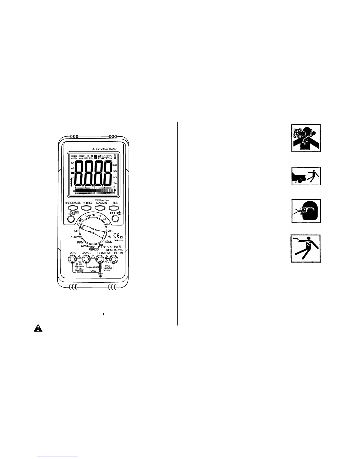
Safety precautions
Safety
DANGER
Engines produce carbon monoxide which
is odorless, causes slower reaction time,
and can lead to serious injury. When the
engine is operating, keep service areas
WELL VENTILATED or attach the vehicle
exhaust system to the shop exhaust
removal system.
Set the parking brake and block the
wheels before testing or repairing the
vehicle. It is especially important to block
the wheels on front-wheel drive vehicles;
the parking brake does not hold the drive
wheels.
Wear an eye shield when testing or
repairing vehicles.
Exceeding the limits of this meter is
dangerous.This will expose you to serious
or possibly fatal injury. Carefully read and
understand the cautions and the
specification limits of this meter.
Voltage between any terminal and ground
must not exceed 1000V DC or 750V AC.
Use caution when measuring voltage above 25V DC or 25V AC.
Circuit tested must be protected by a 20A fuse or circuit breaker.
Do not use the meter if it has been damaged.
Do not use the test leads if the insulation is damaged or if metal
is exposed.
CAP
Hz
20A
MAX every
For
MAX
FUSED
15 min.
FUSED
20A MAX
30 sec.
400mA
500V
1000VDC
750VAC
MAX
-PERIOD
AmA
μ
DWELL
RPM
ms
¦¸
RPM
COM
DWELL
ms-PULSE
%duty
V
x10RPM
OFF
24
¡ã
C
CAP
¡ã
¦¸
Hz
20A
A
F
μ
mA
ms
TEMP.
%
CEM
TRIG¡À
Page 3
3 4
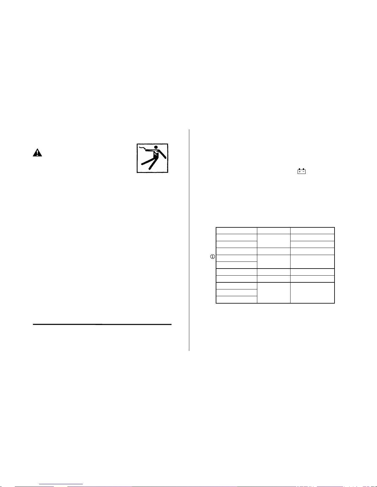
Safety Cont’d
…
Danger
Avoid electrical shock: do not touch the test
leads, tips or the circuit being tested.
Do not try a voltage measurement with the
test leads in the 20A or the mA terminal.
When testing for the presence of voltage or current, make sure
the meter is functioning correctly. Take a reading of a known
voltage or current before accepting a zero reading.
Choose the proper range and function for the measurement. Do
not try voltage or current measurements that may exceed the
ratings marked on the Function/Range switch or terminal.
When measuring current, connect the meter in series with the
load.
Never connect more than one set of test leads to the meter.
Disconnect the live test lead before disconnecting the common
test lead.
The mA and the 20A terminals are protected by fuses. To avoid
possible injury or damage, use only in circuits limited to 400mA
or 20A for 30 seconds.
See also…
Fuse Replacement
Safety Cont’d
…
IMPORTANT
To maintain accuracy of the meter,replace the discharged battery
immediately when the battery symbol appears on the
meter display.
Avoid measuring error from outside interference.Keep the meter
away from spark plug or coil wires.
Avoid damaging the meter when testing voltage.Disconnect the
test leads from the test points before changing functions.
Do not exceed the limits shown in the table below:
Function
Terminal
Input limit
AC Volts
V-Ω -RPM
750Volts AC rms
DC Volts
1000Volts DC
Frequency
V-Ω -RPM
250VoltsAC/DC
Ohm(resistance)
V-Ω -RPM
250VoltsAC DC
Diode
AC/DC μ A mA
μ A / mA
400mAAC/DC
AC/DC20A
20A
*20AAC/DC
RPM
V-Ω -RPM
250Volts AC/DC
Duty Cycle(%)
Dwell angle
* 20 Amp measurement for 30 seconds maximum.
① Ohms can not be measured if voltage is present, ohms
can be measured only in a non-powered circuit. However,
the meter is protected to 250 volts.
Page 4
5 6
Notes:
Getting Started
his chapter will help you get started. It describes the basic
functions of the Meter.
Page 5
7 8
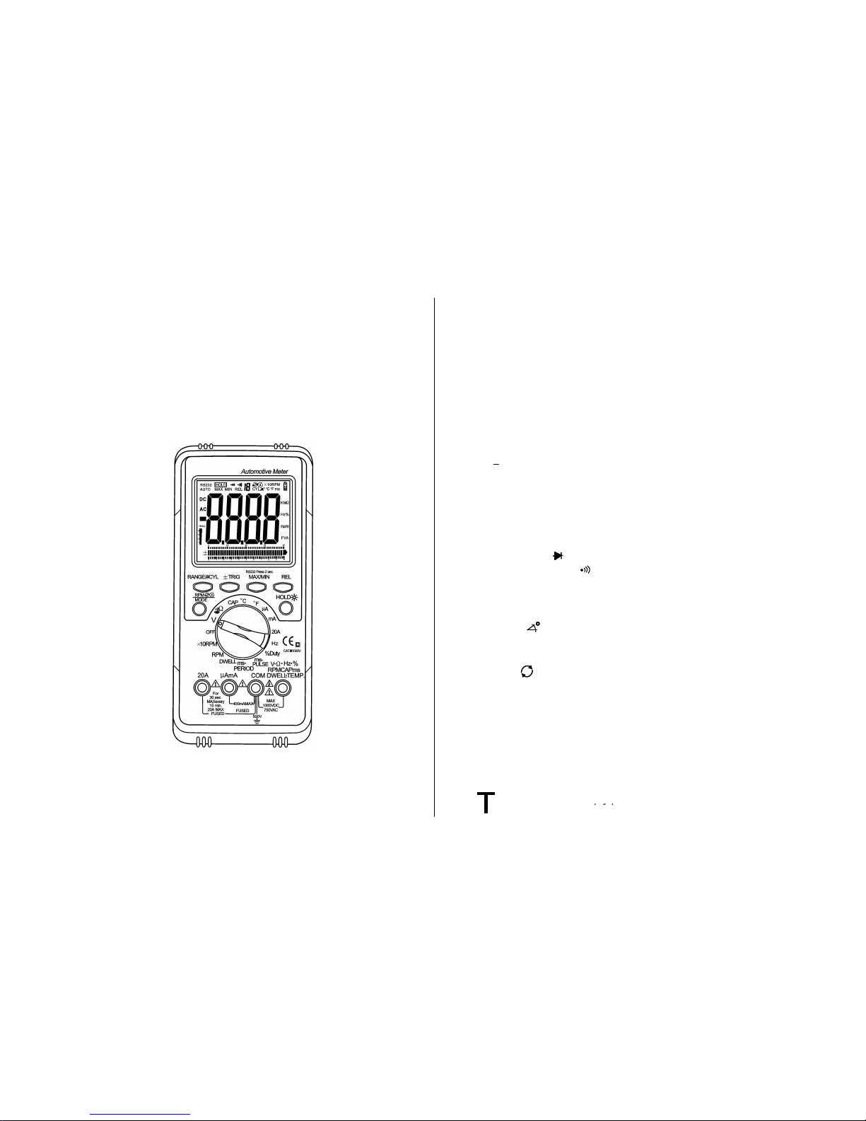
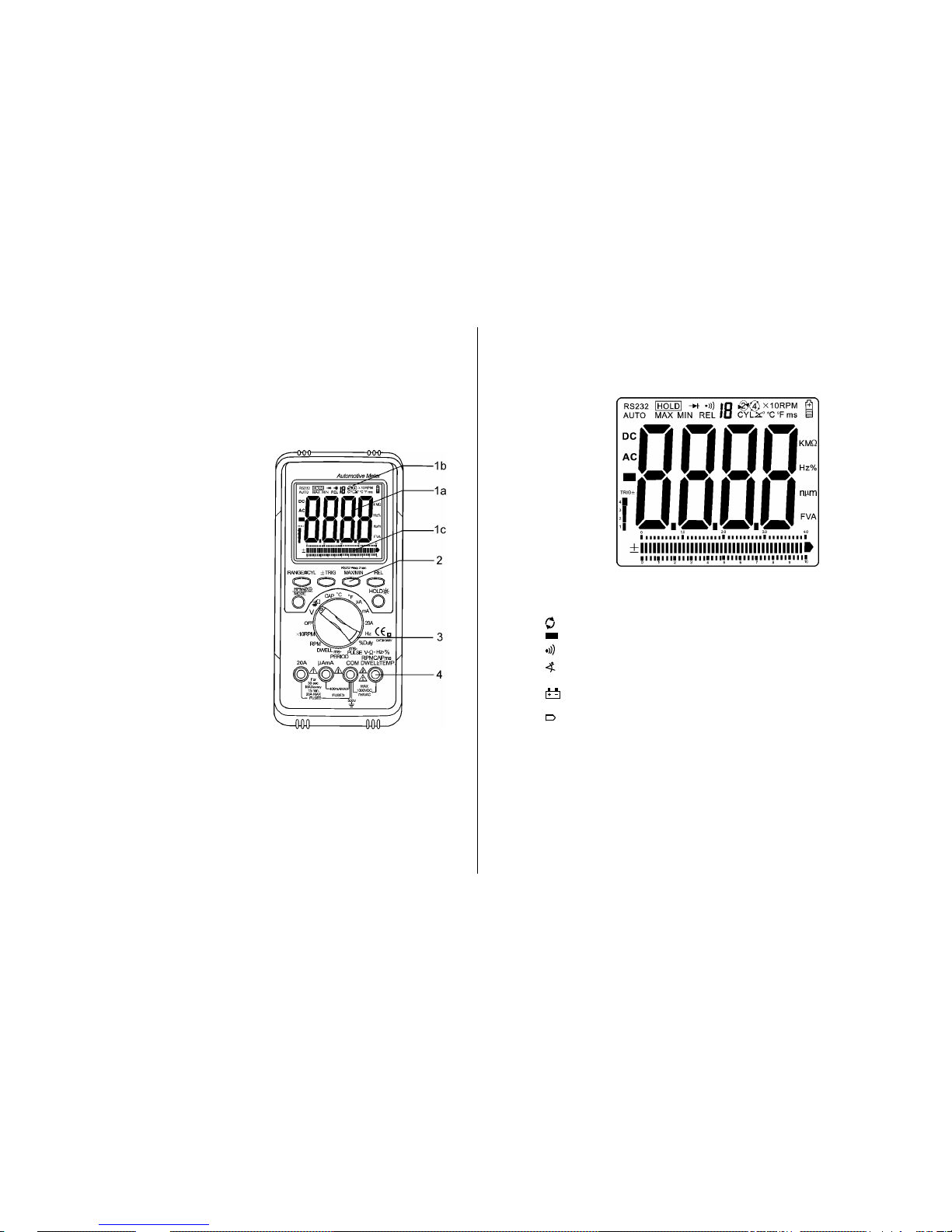
Meter Basics
1. Digital and Analog display
Display features:
a. Four character digital display
b. Symbols to identify function
c. Analog bar graph
The digital display is best for
stable input. The bar graph is best
for rapidly changing input.
2. Function buttons
Press the button to select a
function. A symbol will display to
verify your choice.
3. Rotary Selector Switch
Turn this switch to select a
function or turn the meter OFF.
4. Volts Terminal
The Red test lead is used to
measure Amps, Volts, Ohms,
TEMP, Hz, RPM, Cap, mS and
Dwell.
The Black test lead is used
in the Common(COM) terminal for
all tests
Meter Basics Cont’d…
Digital and Analog display
AC DC Press the Mode button to select Alternating Current
(AC) or Direct Current (DC)
HOLD Press Hold to hold data display or resume testing.
RPM (Tach)
Negative Polarity Indicator
Continuity Test
When Dwell (# of cylinders) is selected with the
rotary switch.
Low Battery Replace the master battery when this
symbol displays.
Analog bar Graph display with polarity.
Units of measure:
Kilo (k=1,000)
Hertz (Hz)
Milli (M=1/1000,)
Volts (V)
mega(m=1,000,000)
ohms (Ω)
dwell degrees
duty percent (%)
Page 6
9 10
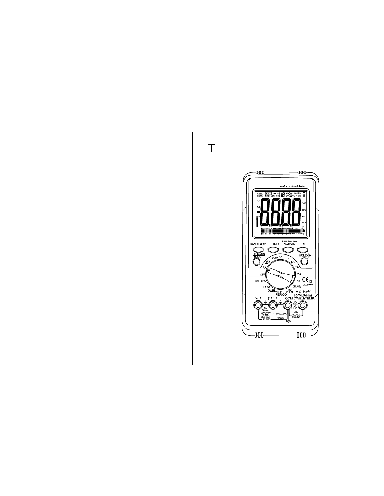
Meter Basics Cont’d…
Function and Range Select
Turn the rotary switch in either
direction to select a function.
Most functions also have ranges.
Always select a range higher
than you expect the current or
voltage to be. Then select a lower
range if better accuracy is
needed.
If the range is too high, the
readings are less accurate.
If the range is too low, the
meter shows (over
limit).
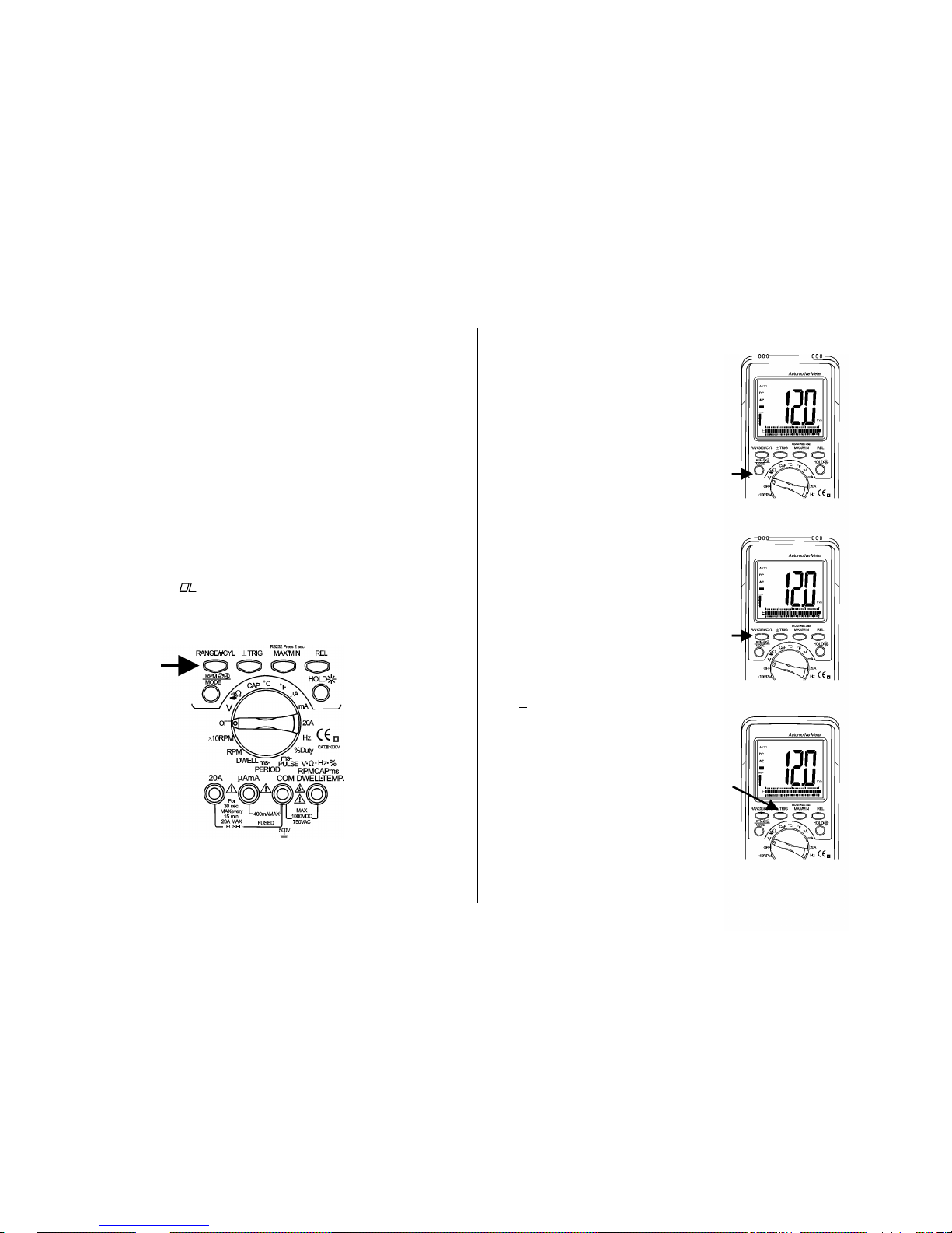
Push–button Functions
Mode Button
Press the Mode button to toggle
between DC and AC in the
voltage & current measurements.
Range / # CYL Select
The range is automatically
selected by the meter. You can
also manually select a range or
DWELL (#CYL) range within a
function by pressing the
RANGE button.
Range Exit
To exit the RANGE mode and
return to autoranging, press and
hold the RANGE button for 2
seconds.
Note:
· If the range is too high, the
readings are less accurate.
· If the range is too low, the
meter shows OL (over limit).
+ TRIG
Toggles between a Negative (-)
and Positive (+) Trigger Slope
when the Meter is in the
ms-pulse, %duty cycle mode,
press this button down for 2
seconds to toggle between
a negative(-) and positive (+)
trigger slope.
Page 7

11 12
The change in the trigger slope is indicated by a + or – shown at
the lower left corner of the display.
The Meter defaults to a – trigger slope whenever the Meter is in
the Hz, %duty, ms-pulse, ms-period, dwell & RPM.
Once the trigger slope is selected, press this button repeatedly to
adjust trigger level if the meter reading is too high or unstable
The Trigger Level has five steps and is different for each function
combination.
Press this TRIG button to move one step at a time in order to
select a suitable trigger level.
The trigger level is indicated by the number above the “trig” symbol
at the lower left corner of the LCD.
The number of steps on the LCD is also a good indication of the
trigger level.
Function Step
Trigger Level
RPM, ms-Pulse,ms-Period,Dwell, %Duty,Hz
4
+7.2v 3 +4.1V 2 +2.1 V
1
+0.8 V
Data Hold/ Backlight
The Data Hold Feature stores the
last reading in memory.
Press the Data Hold button
once to hold the present
reading.
Press the Data Hold button
again to exit and resume
normal readings.
Press the Data Hold button for one
second to turn the backlight on
and press the button a second
time to turn the backlight off.
MAX/ MIN /RS232
Press MAX/MIN to enter, MAX MIN
recording mode. MAX/MIN function is
operative in manual range only!
Select the proper range before
activating MAX MIN to ensure that the
MZX/MIN reading will not exceed the
testing range. Press once to select MAX
Press again to select MIN and
press again release MAX/MIN
recording function.
Press this button down for 2 seconds to
select RS232 PC interface mode.
Relative Mode
The relative measurement feature
allows you to make measurements
relative to a stored reference value.
A reference voltage, current, etc.
can be stored and measurements
made in comparison to that value.
Page 8

13 14
The displayed value is the difference between the reference value
and the measured value.
1. Perform the measurement as described in the operating
instructions.
2. Press the REL button to store the reading in the display and
the "REL" indicator will appear on the display.
3.The display will now indicate the difference between the stored
value and the measured value.
4.Press the REL button to exit the relative mode.
Meter Functions - Voltage (V)
The meter will automatically
select he best voltage (V) range.
Select DCV or ACV with the
MODE button.
Insert:
Black lead in COM terminal.
Red lead in V-Ω -PRM terminal
Touch the Black probe to ground or
to the negative (-) circuit
Touch the Red probe to the circuit
coming from the power source
IMPORTANT: Voltage must be
measuring in parallel (Red probe
measuring circuit from power
source).
Accuracy
Selection of a lower range will
move the decimal point one
place and increase the accuracy.
An “OL” display means the
range is too low. Select the next
higher range.
Analog Bar Graph
The Bar Graph is easiest to
read when the data causes
the digital display to rapidly
change. It is also useful for
trend setting or directional
data.
WARNING
When measuring voltage,
be sure the Red test lead is
in the terminal marked “V”.
If the test lead is in an Amp
(A) or
Milliampere (mA) terminal,
you may be injured or the
meter damaged.
Page 9

15 16
Meter Functions – Resistance (Ω)
IMPORTANT: If you are testing
an application that has capacitors
in the circuit, be sure to turn the
power OFF on the test circuit and
discharge all capacitors. Accurate
measurement is not possible if
external or residual voltage is
present.
Select the resistance ( Ω )
range with the rotary switch.
Select the resistance( Ω )
range with the button labeled
“R ANGE” , if m or e a ccu ra te
measurement is desired.
Insert:
Black lead in COM terminal.
Red lead in V- Ω -RPM
terminal.
Touch the test lead probes across
the resistor to be tested.
Meter Functions –Diode Check ( )
IMPORTANT: Turn the power OFF to
the test circuit
Select the Diode Check ( )
function with the rotary switch.
Insert:
Black lead in COM terminal.
Red lead in V-Ω-RPM terminal.
Touch the Black test probe to the
negative (-) side of the diode.
Touch the Red test probe to the positive
(+) side of the diode.
Reverse the probes: Black to the positive
(+) side and Red to the negative (-) side.
Note:
A “good” diode will read low in one
`direction and high in the other direction
when the probes are reversed (or vice
versa).
A defective diode will have the same
reading in both directions or read
between 1.0 to 3.0 V. in both directions
Diode
- to +
Reverse
Probes
+ to -
Good
.4 to .9V
OL
OL
.4 to .9V
Bad
OL
1.0 to 3.0V
1.0 to 3.0V
OL
.4 to .9V
.4 to .9V
OL
OL
.000V
.000V
Page 10

17 18
Meter Functions –Audible Continuity ( )
IMPORTANT: Turn the power
OFF on the test circuit
Select the Audible Continuity
( ) function with the rotary
switch and mode button
Insert:
Black lead in COM terminal.
Red lead in V- Ω -RPM
terminal.
Connect one test probe to each
end of the circuit to be tested.
Circuit complete, the meter will
beep continuously.
Circuit open, there is no beep
and the display shows to OL
(over limit).
Meter Functions –AC or DC Current (A)
IMPORTANT: All current measured
flows through the meter.
It is important that you do not:
Measure current greater than
600 Volts AC or DC, with
respect to ground.
Do Not Exceed 30 seconds
when measuring continuous
current between 1A-20A.
Allow five minutes for cool
down before continuing.
Select the 20A., mA or μA
range with the rotary switch.
Press the Mode button to
select AC or DC.
Insert:
Black lead in COM terminal.
Red lead in the 20A or mA
terminal (select 20A if you are
unsure of the current draw).
IMPORTANT: Turn OFF all power
to the circuit or disconnect the
circuit from the power source.
Connect:
The Red probe to the side of the
circuit closest to the power
source.
The Black probe to the side of
the circuit to ground.
Turn the power ON and test.
Note:
Current must always be
measured with the meter test
probes connected in series,
as described.
Page 11

19 20
Meter Functions –Temperature (℃/ 0F )
IMPORTANT: To avoid heat
damage to the meter, keep
it away from sources of
very high temperature. The
life of the Temperature
Probe is also reduced
when subjected to very
high temperatures. Probe
operating range is
–4o to 1,400 oF.
Select the Temperature
( ℃ / 0F ) function with the
rotary switch.
Insert the temperature probe
connector into the K-type
thermocouple socket.
Touch the end of the
temperature sensor to the area
or surface of the object to be
measured.
Temperature
Sensor
Temperature probe
Meter Functions –Frequency(Hz)
Select the Frequency
(Freq) setting with the rotary
switch.
Adjust the trigger level to
the setting that gives the
most stable and
accurate reading.
Insert:
Black lead in COM terminal.
Red lead in V-Ω-RPM terminal.
Connect the Black test probe
to ground.
Connect the Red test probe to
the “signal out” wire of the
sensor to be tested.
Page 12

21 22
Meter Functions-Dwell ( )
Select the proper Dwell
range with the rotary switch.
Insert:
Black lead in COM terminal.
Red lead in V- Ω -RPM
terminal.
Connect the Black test probe to
ground.
Connect the Red test probe to
the wire that connects to the
breaker points (see illustration).
Meter Functions-Duty Cycle (%)
Select the % Duty Cycle
range with the rotary switch.
Insert:
Black lead in COM terminal.
Red lead in V-Ω-RPM terminal.
Connect the Black test probe to
ground.
Connect the Red test probe to
the signal wire circuit.
The illustration for a mixture
control solenoid is shown with the
metering rod in the closed
position. The meter will display
the percentage of time the
plunger is in the closed position.
(low duty cycle) during one duty
cycle.
Page 13

23 24
Meter Functions- ms-PULSE (Pulse Width) &
ms- PERIOD (Period)
Pulse Width is the length of time an actuator is energized. For
example, fuel injectors are activated by an electronic pulse from
the Engine Control Module (ECM).
This pulse generates a magnetic field that pulls the injectors nozzle
valve open.
The pulse ends and the injector nozzle is closed.
This open to close time is the Pulse Width and is measured in
milliseconds( ms).
The most common automotive application for measuring pulse
width is on fuel injectors.
You can also measure the pulse width of the fuel mixture control
solenoid and the idle air control motor.
This exercise shows how to measure Pulse Width on Port Fuel
injectors.
To measure pulse width (mS):
Select the mS-Pulse function
with the rotary switch .
Press the ± TRIG button for
2 seconds until the negative
(-) trigger slope is displayed
on the lower left side of the
display.
NOTE : The applied time for
most fuel injectors is
displayed on the
negative (-) slope.
Insert:
Black lead in COM jack.
Red lead in RPM-V-Ω jack.
Connect:
Jumper wires between the fuel
injector and the harness
connector.
Black test probe to a good
ground at the fuel injector or the
negative (-) vehicle battery post.
Red test probe to the fuel
injector solenoid driver input on
the jumper cable.
Start the engine. A pulse width in
milliseconds should be read.
If reading is too high or
unstable,,adjust the trigger level
by pressing the ± TRIG button
for improved reading.
Page 14

25 26
Meter Functions-RPM/×10RPM
Select the RPM range with the
rotary switch.
OR
Select the × 10RPM range
with the rotary switch (1,000 to
12,000 RPM). Multiply the
displayed reading by ten to get
actual RPM.
Press STROKE / DIS
button toward select through
RPM for 4-stroke, RPM
For 2-stroke and DIS.
Insert the inductive pickup
connecting terminal into the
meter.
Black lead in COM terminal.
Red lead in V- Ω -RPM
terminal.
Connect the inductive pickup to
a spark plug wire. If no reading
is received, unhook the clamp,
turn it over and connect again.
Note:
Position the inductive pick-up as far away from the distributor and the
exhaust manifold as possible.
Position the inductive pick-up to within six inches of the spark plug or move
it to another plug wire if no reading or an erratic reading is received.
RPM 4 : For RPM of 4-stroke engines which have 1 ignition on
every 4 engine strokes
RPM 2 : For RPM of DIS ( Distributorless lgnition System) &
2-stroke engines which Have 1 ignition on every 2
engine strokes
PLEASE NOTE- THE RPM PICK-UP HAS AN ADJUSTABLE SENSITIVITY
SWITCH THAT CAN ALSO BE USED TO CORRECT AN
UNSTABLE READING.
Maintenance
Replacing The Battery
WARNING: To avoid electric shock, disconnect the test leads
from any source of voltage before removing the battery door.
1. When the battery become drained or drop below the operating
voltage, “ ” will appear in the right-hand side of the LCD
display. The battery should be replaced.
2. Follow instructions for installing battery. See the Battery
Installation section below.
3. Dispose of the old battery properly.
WARNING: To avoid electric shock, do not operate your meter
until the battery door is in place and fastened securely.
Battery Installation
WARNING: To avoid electric shock, disconnect the test leads
from any source of voltage before removing the battery door.
1. Disconnect the test leads from the meter.
2. Open the battery door by loosening the screw using a Phillips
head screwdriver.
3. Insert the battery into battery holder, observing the correct
polarity.
4. Put the battery door back in place. Secure with the one screw.
WARNING: To avoid electric shock, do not operate the meter
until the battery door is in place and fastened securely.
NOTE: If your meter does not work properly, check the fuses and
battery to make sure that they are still good and that they
are properly inserted.
4
2 4 2
Page 15

27 28
Replacing The Fuses
WARNING: To avoid electric shock, disconnect the test leads
from any source of voltage before removing the fuse door.
1. Disconnect the test leads from the meter and any item under
test.
2. Open the fuse door by loosening the screw on the door using a
Phillips head screwdriver.
3. Remove the old fuse from its holder by gently pulling it out.
4. Install the new fuse into the holder.
5. Always use a fuse of the proper size and value (0.5A/250V fast
blow for the 400mA range, 20A/500V fast blow for the20A
range).
6. Put the fuse door back in place. Insert the screw and tighten it
securely.
WARNING: To avoid electric shock, do not operate your meter until
the fuse door is in place and fastened securely
Trouble Shooting
1. Meter will not turn ON.
Check the battery contacts for a tight fit.
Check for a minimum battery voltage of 8.0 volts.
2. Ampere reading is erratic or there is no reading at all.
Disassemble the meter back cover and test the fuses for
continuity.
3. Meter reading is erratic.
Printed circuit board damaged from handling with hands.
Low battery.
Open circuit in a test lead (frayed or broken wire).
Wrong range selected.
“Blown” fuse.
4. Meter readings do not change.
“Hold” feature is still toggled ON.
F20A,500V
Page 16

29 30
General Specifications
General Specifications
· Safety: Designed to Protection Class III requirement of
EN61010-1 over-voltage Category III (CATIII).
· Maximum Voltage: 500V rms. (Between any terminal and
earth ground)
· RS232: Optically isolated PC interface-optional RS-232 cable
windows® 95/98/2000/XP compatible software allows
user to collect, display, plot and save data.
Display: 4 3/4 digit (4000 counts) liquid crystal display (LCD),
with function and units sign annunciators.
Analog Bar Graph: 40 segments with measurements 15 times
per second.
Polarity: Automatic, (-) negative polarity indication.
Overrange Indication: “OL” mark indication.
Low Battery Indication: The is displayed when the
battery voltage drops below the
operating level.
Auto power off: Meter automatically shuts down after approx.
30 minutes of inactivity.
Measurement Rate: 2 times per second, nominal.
Operating Environment: 0℃ to 50℃
(32 0F to 122 0F) at<70% R.H.
Storage Environment: -20℃ to 60℃ (-4 F to 140 )
at<80% R.H.
Temperature Coefficient: 0.2×(specified accuracy)/ ℃
(<18℃ or>28℃) .
Power: Single standard 9 Volt battery
(NEDA 1604 or IEC 6F22).
Battery Life: 200 hours typical with alkaline battery.
Fuse: 20A/500V, φ 10.3 × 38mm fast acting ceramic type.
0.5A/250V,φ 5×20mm fast acting ceramic type.
· Dimensions: 197 (H) x 88.4 (W) x 41.2 (D) mm
· Weight: Approx.: 635g including holster.
Electrical Specifications
Electrical Specifications
*Accuracy is given as±([% of reading]+[number of least significant
digits]) at 18℃ to 28℃(65 F to 83 F), with relative humidity up to
70%.
RPM (Tach)
Range
Resolution
Accuracy
RPM 4
600~4000
RPM
1 RPM
+2 % of rdg + 4 dgts
600~12000
RPM
(X10 RPM)
10 RPM
RPM2/DIS
300~4000
RPM
1 RPM
300~6000
RPM
(X10 RPM)
10 RPM
Effect Reading: >600 RPM
Overload protection: 250V dc or ac rms.
Dwell Angle
Cylinder
Range
Resolution
Accuracy
1CYL
0~360.0°
0.1°
+2.0% of rdg + 4 dgts
2CYL
0~180.0°
3CYL
0~120.0°
4CYL
0~90.0°
5CYL
0~72.0°
6CYL
0~60.0°
8CYL
0~45.0°
10CYL
0~36.0°
12CYL
0~30.0°
Page 17

31 32
Overload protection: 250V dc or ac rms.
DC Voltage (Auto-ranging for uA and mA)
Range
Resolution
Accuracy
400.0mV
0.1mV
+0.5% of rdg + 2 dgts
4.000V
1mV
+1.5% of rdg + 2 dgts
40.00V
10mV
400.0V
100mV
1000V
1V
+1.8% of rdg + 2 dgts
Input Impedance: 10MΩ .
Maximum Input: 1000V dc or 750V ac rms.
AC Voltage (Auto-ranging except 400mV)
Range
Resolution
Accuracy
400.0mV
0.1mV
+1.5%of rdg + 60 dgts
4.000V
1mV
+1.0% of rdg + 3 dgts
40.00V
10mV
+1.5% of rdg + 3 dgts
400.0V
100mV
750V
1V
+2.0% of rdg + 4 dgts
Input Impedance: 10MΩ
Frequency Range: 50 to 400Hz
Maximum Input: 1000V dc or 750V ac rms.
DC Current (Auto-ranging for uA and mA)
Range
Resolution
Accuracy
400.0uA
0.1uA
+1.0% of rdg + 3 dgts
4000uA
1uA
+1.5% of rdg + 3 dgts
40.00mA
10uA
400.0mA
100uA
4A
1mA
+2.5% of rdg + 5 dgts
20A
10mA
Overload Protection: 0.5A / 250V and 20A / 500V Fuse.
Maximum Input: 400mA dc or 400mA ac rms on uA / mA ranges,
20A dc or ac rms on 20A range.
AC Current (Auto-ranging)
Range
Resolution
Accuracy
400.0uA
0.1uA
+1.5% of rdg + 5 dgts
4000uA
1uA
+1.8% of rdg + 5 dgts
40.00mA
10uA
400.0mA
100uA
4A
1mA
+3.0% of rdg + 7 dgts
20A
10mA
Overload Protection: 0.5A / 250V and 20A / 500V Fuse.
Frequency Range: 50 to 400 Hz
Maximum Input: 400mA dc or 400mA ac rms on uA / mA ranges,
20A dc or ac rms on 20A range.
Resistance (Auto-ranging)-
Range
Resolution
Accuracy
400.0Ω
0.1Ω
+1.2% of rdg + 4 dgts
4.000kΩ
1Ω
+1.0% of rdg + 2 dgts
40.00kΩ
10Ω
+1.2% of rdg + 2 dgts
400.0kΩ
100Ω
4.000MΩ
1kΩ
40.00MΩ
10kΩ
+2.0% of rdg + 3 dgts
Input Protection: 250V dc or 250V ac rms.
Capacitance (Auto-ranging)
Range
Resolution
Accuracy
40.00nF
10pF
+5.0% of rdg + 7 dgts
400.0nF
0.1nF
Page 18

33 34
4.000uF
1nF
+3.0% of rdg + 5 dgts
40.00uF
10nF
100.0uF
0.1uF
+5.0% of rdg + 5 dgts
Input Protection: 250V dc or 250V ac rms.
Frequency (Auto-ranging)
Range
Resolution
Accuracy
5Hz
0.001Hz
+1.5% of rdg + 5 dgts
50Hz
0.01Hz
500Hz
0.1Hz
+1.2% of rdg + 3 dgts
5kHz
1Hz
30.00kHz
10Hz
Sensitivity: >5V RMS MIN.
Overload protection: 250V dc or ac rms.
Duty Cycle
Range
Resolution
Accuracy
0.1%~99.9%
0.1%
+1.2% of rdg + 4 dgts
Pulse width: >100us, <100ms; (Continued next page)
Sensitivity: <0.5V RMS
Overload protection: 250V dc or ac rms.
Period
Range
Resolution
Accuracy
2.0~ 20.0ms
0.1ms
+3% of rdg + 10 dgts
Overload protection: 250V dc or ac rms.
Pulse Width
Range
Resolution
Accuracy
2.0~ 10.0ms
0.1ms
+3% of rdg +10 dgts
Overload protection: 250V dc or ac rms
Temperature
Range
Resolution
Accuracy
-20oC~+760oC
1 oC
+3% of rdg +5dgts(Meter only,
probe accuracy not included)
-4 oF~+1400 oF
1oF
Sensor: Type K Thermocouple
Diode Test
Test current
Resolution
Accuracy
0.3mA typical
1 mV
+10% of rdg + 5 dgts
Open circuit voltage: 1.5V dc typical
Overload protection: 250V dc or ac rms.
Audible continuity
Audible threshold: Less than 150Ω Test current: <0.3mA
Overload protection: 250V dc or ac rms.
Page 19

35 36
Ready – to – Use Windows® Application
Program
Hardware and Software Requirements
386/25 personal computer, 4 Megabytes of memory or better.
windows® 95 or above.
RS232: Optically isolated PC interface-optional RS-232 cable
windows® 95/98/2000/XP compatible software allows user to
collect, display, plot and save data.
Printing Data and Graph tester report
·Print data tester report
·Please press off line
·Move the cursor to the number of data that you want to print out.
(e.g.: If you want to print the date area from number 0 to 100,
move the cursor to number 0 and click. If you want to print the data
area from number 50 to 100, move the cursor to number 50 and
click).
·Please press printer icon.
·A information show: List "Y" or "N" - press "Y".
·The data tester report will print out the selected data sets.
Print graph tester report
·Please press off line
·Move the cursor to the number of data that you want to print out.
(e.g.: If you want to print the graph area from number 0 to 100,
move the cursor to number 0 and click. If you want to print
the graph area from number 50 to 100, move the cursor to number
50 and click).
·Please press printer icon.
· A information show: List "Y" or "N" - press "N". A information
show Graph "Y" or "N" press "Y".
·The graph tester report will print out the selected graph sets.
Installation of the Windows Application program
A. Start Microsoft ® Windows®
B. Insert disk in drive CD
C. From the program Manager, select file menu and choose Run
D. For Win98 from the start, select Execute.
E. Type E :\setup and press Enter Key
Note: If you are using 386 PC, it might takes more than 3 minutes.
Description of Windows® Application Program
When the ICON “Panel” is selected and executed,the program
automatically search for connected DMM/Data Logger or available
serial port. If no serial port is available, then a message of “:No
Com:” shall be displayed, and the program exits itself. Once
communication port is setup, a main window will be displayed on
the screen. The Layout of the window is as Figure:
Page 20

37 38
Note: Please click “Help” on the PC interface for detailed
instruction.
 Loading...