

Page 1
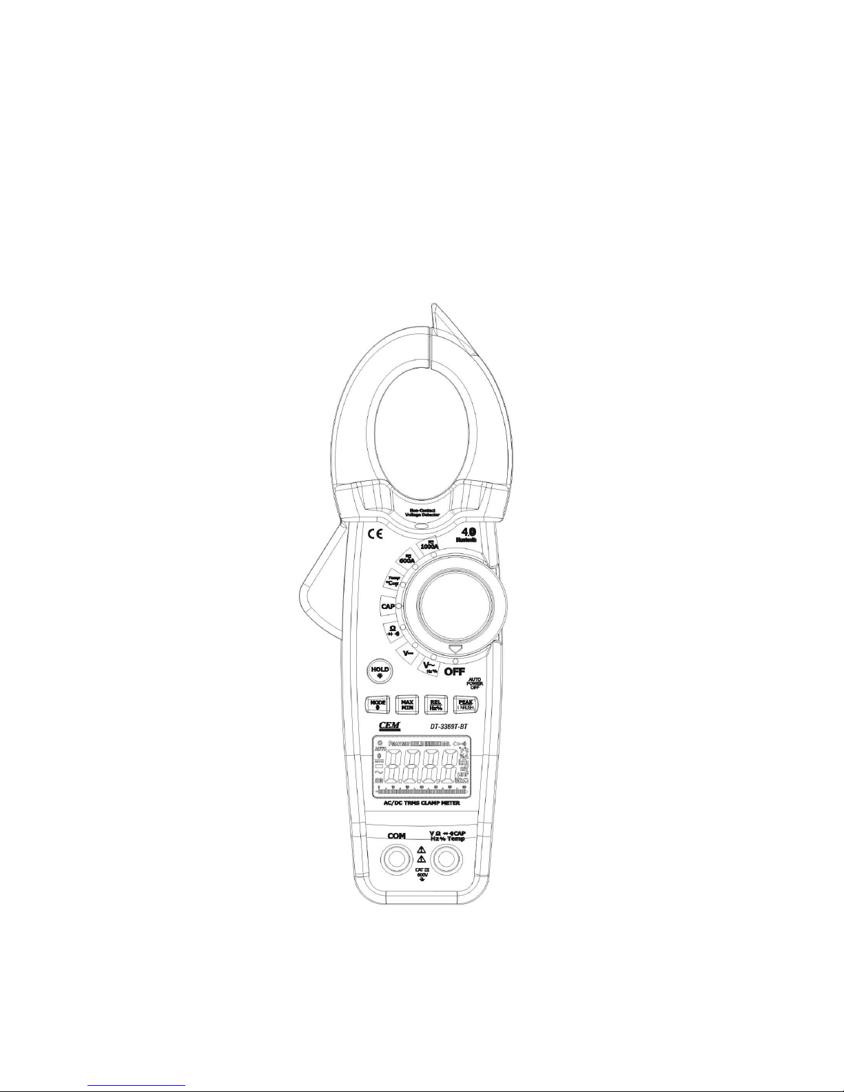
DT-3369T-BT
AC/DC TRMS CLAMP METER
With Mobile APP
Page 2

Safety
International Safety Symbols
This symbol, adjacent to another symbol or terminal, indicates the user must refer
to the manual for further information.
This symbol, adjacent to a terminal, indicates that, under normal use, hazardous
voltages may be present
Double insulation
SAFETY NOTES
• Do not exceed the maximum allowable input range of any function.
• Do not apply voltage to meter when resistance function is selected.
• Set the function switch OFF when the meter is not in use.
• Remove the battery if meter is to be stored for longer than 60 days.
WARNINGS
• Set function switch to the appropriate position before measuring.
• When measuring volts do not switch to current/resistance modes.
• Do not measure current on a circuit whose voltage exceeds 600V.
• When changing ranges always disconnect the test leads from the circuit under test.
• Changes or modifications to this unit not expressly approved by the party
responsible for compliance could void the user's authority to operate the
equipment.
Note: This equipment has been tested and found to comply with the limits for a
Class B digital device, pursuant to Part 15 of the FCC Rules. These limits are
designed to provide
reasonable protection against harmful interference in a residential installation.
This equipment generates, uses and can radiate radio frequency energy and, if
not installed and used in
accordance with the instructions, may cause harmful interference to radio
communications. However, there is no guarantee that interference will not occur in
a particular installation. If this equipment does cause harmful interference to redio
or television reception, which can be determined by turning the equipment off and
on, the user is encouraged to try to correct
the interference by one or more of the following measures:
Reorient or relocate the receiving antenna
Increase the separation between the equipment and receiver
Connect the equipment into an outlet on a circuit different from that to which the
receiver is connected
Consult the dealer or an experienced radio/TV technician for help.
The device must not be co-located or operating in conjunction with any other
antenna or transmitter.
Page 3

CAUTIONS
• Improper use of this meter can cause damage, shock, injury or death. Read and
understand this user manual before operating the meter.
• Always remove the test leads before replacing the battery or fuses.
• Inspect the condition of the test leads and the meter itself for any damage before
operating the meter. Repair or replace any damage before use.
• Use great care when making measurements if the voltages are greater than 25VAC
rms or 35VDC. These voltages are considered a shock hazard.
• Always discharge capacitors and remove power from the device under test before
performing Diode, Resistance or Continuity tests.
• Voltage checks on electrical outlets can be difficult and misleading because of the
uncertainty of connection to the recessed electrical contacts. Other means should
be used to ensure that the terminals are not "live".
• If the equipment is used in a manner not specified by the manufacturer, the
protection provided by the equipment may be impaired.
Function Maximum
Input
A AC, A DC 1000A DC/AC
V DC, V AC 750V DC/AC
Resistance, Capacitance, Frequency,
Diode Test
Temperature 300V DC/ AC
300V DC/AC
Page 4
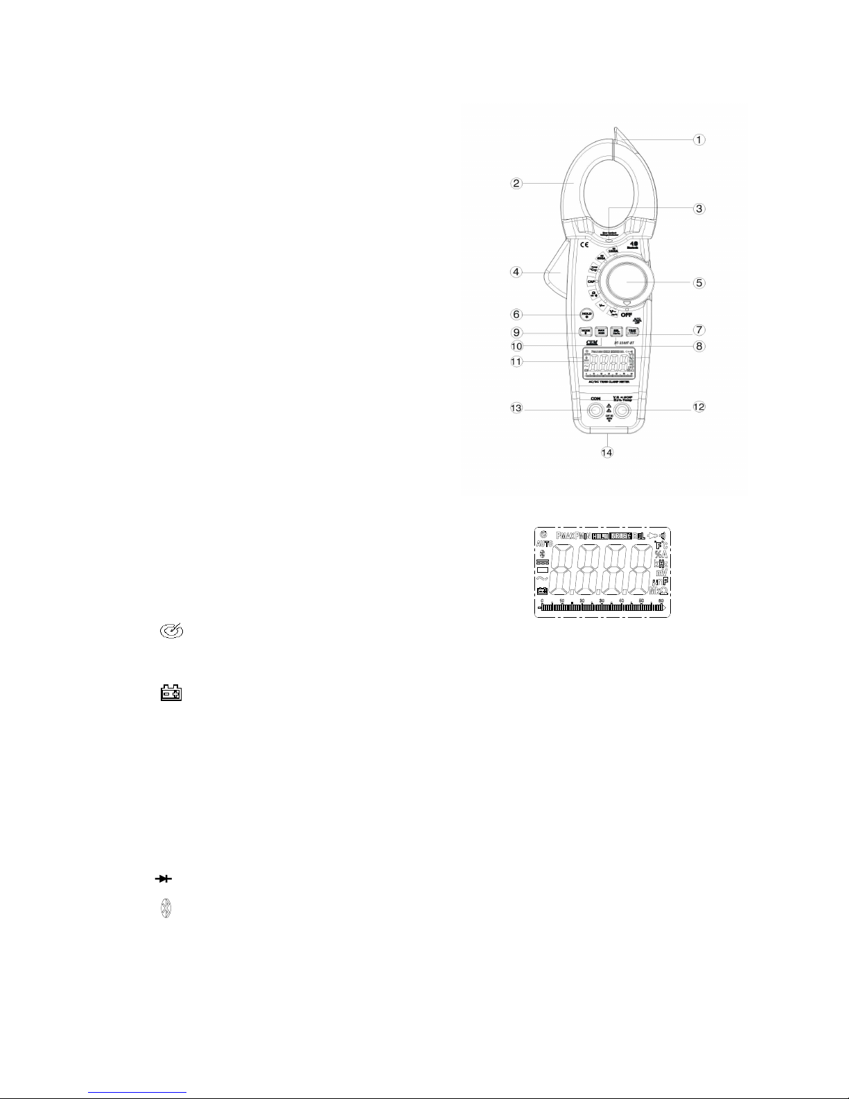
Description
Meter Description
1. NCV Test
2. Current clamp
3. Non-contact AC voltage indicator light
4. Clamp trigger
5. Rotary Function switch
6. Data Hold and Backlight button
7. PEAK and INRUSH button
8. REL and HZ% button
9. MODE select and Bluetooth button
10. Max/Min button
11. LCD display
12. V Ω Diode Continuity CAP TEMP Hz% jack
13. COM input jack
14. Battery Cover
Display icons Description
HOLD Data Hold
Minus sign Negative reading display
0 to 5999 Measurement display digits
REL REL/DCA Zero
MAX/MIN Maximum/Minimum
Auto Power Off
AUTO Auto Range mode
DC/AC Direct Current / Alternating Current
Low battery
mV or V Milli-volts or Volts (Voltage)
Ohms (Resistance)
A Amperes (Current)
F Farad (Capacitance)
Hz/% Hertz (Frequency)/Percent(duty ratio)
o
F and oC Fahrenheit and Celsius units (Temperature)
n, m, μ, M, k Unit of measure prefixes: nano, milli, micro, mega, and kilo
•))) Continuity test
Diode test
Bluetooth4.0
Page 5

Specifications
Function Range Resolution
AC True RMS
Current
(Auto Rang)
60.00 10 mA +2.5% of rdg + 8 digits
600.0A 100mA +2.5% of rdg + 8 digits
1000A 1A +2.8% of rdg + 8 digits
Over rang protection: Maximum input 1000A
Accuracy specified from 5% to 100% of the measuring range
Frequency
DC Current
(Auto Rang)
Response: 50Hz to 60Hz True RMS
Function Range Resolution
60.00A 10mA +2.5% of rdg + 8 digits
600.0A 100mA +2.5% of rdg + 8 digits
1000A 1A +2.8% of rdg + 8 digits
(% of reading + digits)
Over rang protection: Maximum input 1000A
Function Range Resolution
600.0mV 0.1mV +0.9% of rdg + 5digits
DC Voltage
(Auto-ranging)
Maximum Input:750V dc
Function Range Resolution
AC True RMS
Voltage
(Auto-ranging)
AC Response: 50 Hz to 1kHz
Accuracy specified from 5% to 100% of the measuring range
Accuracy PEAK function: ±10%rdg
Maximum Input: 750V ac rms.
Function Range Resolution
Resistance
(Auto-ranging)
6.000V 1mV +1.0% of rdg + 3digits
60.00V 10mV +1.0% of rdg + 3digits
600.0V 100mV +1.0% of rdg + 3digits
6.000V 1mV +1.2% of rdg + 5digits
60.00V 10mV +1.2% of rdg + 5digits
600.0V 100mV +1.5% of rdg + 5digits
600.0Ω 0.1Ω +1% of rdg + 4digits
6.000kΩ 1Ω +1.5% of rdg + 2digits
60.00kΩ 10Ω +1.5% of rdg + 2digits
600.0kΩ 100Ω +1.5% of rdg + 2digits
6.000MΩ 1kΩ +2.0% of rdg + 5digits
60.00MΩ 10kΩ +3% of rdg + 8digits
(% of reading + digits)
(% of reading + digits)
(% of reading + digits)
Accuracy
(% of reading + digits)
Accuracy
Accuracy
Accuracy
Accuracy
Input Protection: 300V dc or 300V ac rms.
Page 6

Function Range Resolution
60.00nF 10pF +5% of rdg + 30digits
600.0nF 0.1nF +3% of rdg + 5digits
Capacitance
(Auto-ranging)
6.000uF 1nF +3% of rdg + 5digits
60.00uF 10nF +3% of rdg + 5digits
600.0uF 0.1uF +4% of rdg + 10digits
6000uF 10uF +4.5% of rdg + 10digits
Input Protection: 300V dc or 300V ac rms.
Accuracy is not stated below 6nF
Frequency with test leads(AC Voltage)
Function Range
Frequency
(Auto-ranging)
10Hz to 20kHz ±(1.0% +5 digits)
Input Protection:750V AC rms
Sensitivity: >15V AC rms
Function Range
Frequency
40Hz to 1kHz ±(1.0% +5 digits)
Maximum Input: 1000A AC
Sensitivity: >50A (600A range)
>500A (1000A range)
Function Range Resolution
Duty Cycle
20.0%~80.0% 0.1 +1.2% of rdg + 10digits
Accuracy
(% of reading + digits)
Accuracy
±(% of reading + digits)
Accuracy
±(% of reading + digits)
Accuracy
(% of reading + digits)
Function Range Resolution
Temperature
Sensor: Type K Thermocouple
Input Protection: 300V dc or 300V ac rms.
Accuracy
(% of reading + digits)
-20oC~+760oC 0.1/1 oC +3% of rdg + 5 oC
-4 oF~+1400 oF 0.1/1 oF +3% of rdg + 9oF
Page 7

Function Testing Condition Reading
Diode
Continuity
Input Protection: 300V dc or 300V ac rms.
Forward DCA is approx.1mA,
open circuit Voltage MAX . 3V
Test current MAX. 1.5mA
Forward voltage drop of Diode
Buzzer makes a long sound, While
resistance is less than(50Ω)
General Specifications
Clamp jaw opening 1.2" (30mm) approx.
Blue tooth 4.0
Display 3-6/7 digits (6000 counts) backlit LCD
Continuity check Threshold 50Ω; Test current < 0.5mA
Diode test Test current of 0.3mA typical;
Open circuit voltage < 3VDC typical
Low Battery indication ‘ ’ is displayed
Over-range indication ‘OL’ display
Measurement rate 3 readings per second, nominal
PEAK Captures peaks >1ms
INRUSH 100MS
Temperature sensor Type K thermocouple
Input Impedance 10MΩ (VDC and VAC)
AC response True rms (AAC and VAC)
Operating Temperature 41oF to 104oF (5oC to 40oC)
Storage Temperature -4oF to 140oF (-20oC to 60oC)
Operating Humidity Max 80% up to 87oF (31oC) decreasing linearly to 50% at
104oF(40oC)
Storage Humidity <80%
Operating Altitude 7000ft. (2000meters) maximum.
Battery One (1) 9V Battery
Auto power OFF After approx. 15 minutes
Dimensions & Weight 239 x 80 x 49mm; 305g
Safety For indoor use and in accordance with the requirements for
double insulation to IEC1010-1 (2001): EN61010-2-030
EN61010-2-032 EN61010-2-033 Overvoltage Category III 600V,
Pollution Degree 2.
Page 8

Operation
NOTES: Read and understand all Warning and Caution statements in this operation
manual prior to using this meter. Set the function select switch to the OFF position
when the meter is not in use.
AC/DC Current Measurements
WARNING: Ensure that the test leads are disconnected from the meter before making
current clamp measurements.
1. Set the Function switch to the 1000A, 600A range. If the approx. range of the
measurement is not known, select the highest range then move to the lower ranges
if necessary.
2. Press the REL button to zero the meter display.
3. Use the MODE button to select AC or DC Current.
4. Press the trigger to open jaw. Fully enclose only one conductor. For optimum results,
center the conductor in the jaw.
5. The clamp meter LCD will display the reading.
AC Voltage Measurement
1. Insert the black test lead into the negative COM terminal and the red test lead into
the positive V· ·CAP·TEMP·Hz %·ΩΩΩΩ terminal.
2. Set the function switch to the V~ position.
3. Connect the test leads in parallel to the circuit under test.
4. Read the voltage measurement on the LCD display.
DC Voltage Measurement
1. Insert the black test lead into the negative COM terminal and the red test lead into
the positive V· ·CAP·TEMP·Hz %·ΩΩΩΩ terminal.
2. Set the function switch to the V- position.
3. Connect the test leads in parallel to the circuit under test.
4. Read the voltage measurement on the LCD display.
Resistance
1. Insert the black test lead into the negative COM terminal and the red test lead into
the V· ·CAP·TEMP·Hz %·ΩΩΩΩ positive terminal.
2. Set the function switch to the ΩΩΩΩ
•))).
position.
3. Touch the test probe tips across the circuit or component under test.
4. Read the resistance on the LCD display.
Capacitance Measurements
WARNING: To avoid electric shock, discharge the capacitor under test before
Page 9

measuring.
1. Set the function switch to the CAP position.
2. Insert the black test lead banana plug into the negative COM jack and the re
d test lead banana plug into the V· ·CAP·TEMP·Hz %·ΩΩΩΩ positive jack.
3. Touch the test probe tips across the part under test. If “OL” appears in the d
isplay, remove and discharge the component.
4. Read the capacitance value in the display.
5. The display will indicate the proper decimal point and value.
Note: For very large values of capacitance measurement it can take several minutes
before the final reading stabilizes.
Frequency Measurements
1. Insert the black test lead banana plug into the negative COM jack and the re
d test lead banana plug into the V· ·CAP·TEMP·Hz %·ΩΩΩΩ positive jack.
2. Set the function switch to the V~ Position.
3. Press HZ/% button to select the Frequency (Hz) or Duty cycle (%).
4. Touch the test probe tips across the part under test.
5. Read the value on the display.
6. The display will indicate the proper decimal point and value.
7. In Voltage and Current mode Press HZ/% button to select he Frequency (Hz)
or Duty cycle (%) .
Temperature Measurements
1. Set the function switch to the TEMP position.
2. Insert the Temperature Probe into the negative COM and the
V · ·CAP·TEMP·Hz%·ΩΩΩΩ positive jacks, observing polarity.
3. Touch the Temperature Probe head to the device under test. Continue to touch the
part under test with the probe until the reading stabilizes.
4. Read the temperature on the display. The digital reading will indicate the proper
decimal point and value.
5. Use the MODE button to select oF or oC.
WARNING: To avoid electric shock, be sure the thermocouple probe has been removed
before changing to another measurement function.
Continuity Measurements
1. Insert the black test lead into the negative COM terminal and the red test lead into
the V· ·CAP·TEMP·Hz %·ΩΩΩΩ positive terminal.
Page 10

Detector on a known live circuit to
verify
proper operation
2. Set the function switch to the ΩΩΩΩ
•))).
position.
3. Use the MODE button to select continuity “••••)))”. The display icons will change when
the MODE button is pressed.
4. Touch the test probe tips across the circuit or component under test.
5. If the resistance is < 50Ω, a tone will sound.
Diode Test
1. Insert the black test lead banana plug into the negative COM jack and the re
d test lead banana plug into the V· ·CAP·TEMP·Hz %·ΩΩΩΩ positive jack
2. Turn the function switch to ΩΩΩΩ
•))). position. Use the MODE button to select the
diode function if necessary (diode symbol will appear on the LCD when in Diode test
mode)
3. Touch the test probe tips to the diode or semiconductor junction under test. Note the
meter reading
4. Reverse the test lead polarity by reversing the red and black leads. Note this
reading
5. The diode or junction can be evaluated as follows:
If one reading displays a value (typically 0.400V to 0.900V) and the other
reading displays OL, the diode is good.
If both readings display OL the device is open.
If both readings are very small or ‘0’, the device is shorted.
Non-Contact AC Voltage Measurements
WARNING
1. Touch the probe tip to the hot conductor or insert into the hot side of the electrical
outlet.
2. If AC voltage is present, the detector light will illuminate.
1. NOTE: The conductors in electrical cord sets are often twisted. For best results,
rub the probe tip along a length of the cord to assure placing the tip in close
proximity to the live conductor.
2. NOTE: The detector is designed with high sensitivity. Static electricity or other
sources of energy may randomly trip the sensor. This is normal operation
Mode/Bluetooth
Press Mode/Bluetooth key the selection of double measured functions which are
present at display is possible. In particular this key is active in V· ·CAP· ΩΩΩΩ•))) position
to select among resistance test, diode test, continuity test, and in Temp position to select
:
Risk of Electrocution. Before use, always test the Voltage
Page 11

between oF or oC. and in current position to select between AC or DC current
measurements.
To press and hold the mode key to turn the system on, the auto power off function will be
cancelled.
Press the Mode/Bluetooth until the Bluetooth turns on or off.
PEAK/ INRUSH
NOTE: Only ACV functions can do the peak value measurement.
PEAK Key is the peak value measurement key that acts with trigger.
NOTE: Only ACA functions can do the INRUSH value measurement.
1.
Close motor and then install Jaw or Flexible coil
2.
Press the INRUSH button , “----”will appear in the display.
3.
Open motor and then read the value on the display.
Data Hold/Backlight
To freeze the LCD reading, press the HOLD button. While data hold is active, the HOLD
icon appears on the LCD. Press the HOLD button again to return to normal operation.
The LCD is equipped with backlighting for easier viewing, especially in dimly lit areas.
Press the backlight button to turn the backlight on. Press again to turn the backlight off.
Note :
that the meter does have an auto power off feature as described below.
Relative
1. Press the REL button to zero the display. “ REL ” will appear in the displ
ay. The displayed reading is now the actual value less the stored “zero” valu
e.
2. Press the REL button to view the stored value. “ REL ” will flash in the display.
3. To exit this mode, press and Hold the REL button until “ REL ” is no longer in the
display.
MAX/MIN
Press MAX/IN key the maximum and minimum values are measured. This mode is
activated on each measurement except for continuity test, diode test capacitance test,
frequency test and duty cycle test.
This mode is disabled keeping pressed MAX/MIN key or moving the rotary switch.
HZ/%
With rotary switch on HZ/%, Voltage, Current, positions, the Hz% key permits to select
the frequency test ( Hz ) or the duty cycle test(%).
LCD Backlight Button
Page 12

The LCD is equipped with backlighting for easier viewing, especially in dimly lit areas.
Press the backlight button to turn the backlight on. Press again to turn the backlight off.
Note that the meter does have an auto power off feature as described below.
Automatic Power OFF
In order to conserve battery life, the meter will automatically turn off after approximately
15 minutes. To turn the meter on again, turn the function switch to the OFF position and
then to the desired function position.
Maintenance
WARNING: To avoid electrical shock, disconnect the meter from any circuit, remove the
test leads from the input terminals, and turn OFF the meter before opening the case. Do
not operate the meter with an open case.
Cleaning and Storage
Periodically wipe the case with a damp cloth and mild detergent; do not use abrasiv
es or solvents. If the meter is not to be used for 60 days or more, remove the battery
and store it separately.
Battery Replacement
1. Remove the Phillips head screw that secures the rear battery door
2. Open the battery compartment
3. Replace the 9V battery
4. Secure the battery compartment
Temperature Probe Replacement
The replacement bead wire probe (with banana plug connectors) is Part Number
TP873.
Note: To use a Type K thermocouple probe that is terminated by a subminiature (flat
blade) connector, a subminiature-to-banana plug adaptor (Part Number TP879) is
required.
 Loading...