

Page 1
600857
Rev. 1
8/17
Operation Manual
i
Page 2

Copyrig h t 201 7 by
CEM Corporation
All Rights Reserved
This manual contains proprietary information, which shall not
be reproduced or transferred to other documents
or disclosed to others without prior written permission of
CEM Corporation.
CEM is a registered trademark of CEM Corporation.
Discover is a registered trademark of CEM Corporation.
Patents Pending
CEM Corporation
POB 200
3100 Smith Farm Road
Matthews, North Carolina 28106-0200
(704) 821-7015 (phone)
704-821-7894 (fax)
www.cem.com (website)
Manufactured in the
United States of America
600857
Rev. 1
8/17
ii
Page 3

Table of Contents
Operating Precautions ............................................................................................................................................................. 1
Warnings and Cautions ........................................................................................................................................................... 1
Introduction ............................................................................................................................................................................... 2
Instrument Description ............................................................................................................................................... 3
Front View .......................................................................................................................................................................... 3
User Interface .................................................................................................................................................................... 3
Keypad ............................................................................................................................................................................... 4
Method Status Bar ............................................................................................................................................................ 4
Rear View .......................................................................................................................................................................... 5
Side Views ......................................................................................................................................................................... 5
Sample Stirrer .................................................................................................................................................................... 6
Cooling ............................................................................................................................................................................... 6
System Installation ................................................................................................................................................................... 7
Installation Site .................................................................................................................................................................. 7
Unpacking .......................................................................................................................................................................... 7
Discover SP Installation .................................................................................................................................................... 8
Computer Installation (optional) ........................................................................................................................................ 9
User Login .................................................................................................................................................................. 11
User Logout ................................................................................................................................................................ 11
Microwave Tips........................................................................................................................................................... 12
Closed Vessel Extraction ........................................................................................................................................... 13
Items Required .................................................................................................................................................................. 13
Prepare the Vessel ............................................................................................................................................................ 13
Perform a Method ............................................................................................................................................................. 13
Vessel Removal ................................................................................................................................................................ 14
Load, Save, and Create a New Method .................................................................................................................................. 15
Create a New Method ....................................................................................................................................................... 15
Standard Control ............................................................................................................................................................... 16
Dynamic Control ................................................................................................................................................................ 16
Save Method ..................................................................................................................................................................... 20
Ramp to Temperature Control .......................................................................................................................................... 21
Load Method ...................................................................................................................................................................... 22
Data Review ...................................................................................................................................................................... 22
Delete Method ................................................................................................................................................................... 23
Discover Home ......................................................................................................................................................................... 24
Rxn Programming ............................................................................................................................................................. 24
Logout ................................................................................................................................................................................ 25
ActiVent Home, ActiVent Moving, ActiVent Closed, APM Recovery ............................................................................. 25
System Setup .................................................................................................................................................................... 26
User Setup ......................................................................................................................................................................... 27
Temperature Type ............................................................................................................................................................. 27
Release Limiits .................................................................................................................................................................. 27
User Profiles ................................................................................................................
Clear Password ................................................................................................................................................................. 28
Change Password ............................................................................................................................................................. 28
User Profile Defaults -1 ..................................................................................................................................................... 28
Hold Time .......................................................................................................................................................................... 28
Ramp Time ........................................................................................................................................................................ 29
Temperature ...................................................................................................................................................................... 29
µ Power ........................................................................................................................................................................... 29
...................................................... 28
iii
Page 4

User Profile Defaults- 2 ............................................................................................................................................................ 29
Stirring ................................................................................................................................................................................ 29
Pre-Mix Time ..................................................................................................................................................................... 30
Pressure ............................................................................................................................................................................. 30
Pressure Units .................................................................................................................................................................. 30
User Profile Defaults- 3 ............................................................................................................................................................ 30
Key Beep ........................................................................................................................................................................... 30
Clock Format ..................................................................................................................................................................... 30
Cooling Time ..................................................................................................................................................................... 31
Backup Methods ................................................................................................................................................................ 31
Restore Methods ............................................................................................................................................................... 31
Calibration Setup ............................................................................................................................................................... 31
Temperature ...................................................................................................................................................................... 32
Infrared ............................................................................................................................................................................... 32
Slope .................................................................................................................................................................................. 32
Fiber Optic ......................................................................................................................................................................... 33
Slope .................................................................................................................................................................................. 33
Pressure (10mL APM) ...................................................................................................................................................... 34
Network Setup ................................................................................................................................................................... 34
IP Address ......................................................................................................................................................................... 34
Sub Net Mask .................................................................................................................................................................... 35
Serial Number .................................................................................................................................................................... 35
Peripheral Setup ................................................................................................................................................................ 35
Information ......................................................................................................................................................................... 35
Administrative Functions ................................................................................................................................................... 35
Create New User ............................................................................................................................................................... 35
Create User ....................................................................................................................................................................... 35
User Name......................................................................................................................................................................... 36
Permissions ....................................................................................................................................................................... 36
User Profile ........................................................................................................................................................................ 36
Save User .......................................................................................................................................................................... 37
Edit User ............................................................................................................................................................................ 37
Permissions ....................................................................................................................................................................... 37
User Profile ........................................................................................................................................................................ 37
Save User .......................................................................................................................................................................... 37
Delete User ........................................................................................................................................................................ 38
Administration .................................................................................................................................................................... 38
Maintenance ............................................................................................................................................................................. 39
Interlocks ............................................................................................................................................................................ 39
Cavity ................................................................................................................................................................................. 39
ActiVent .............................................................................................................................................................................. 40
APM Cleaning.................................................................................................................................................................... 42
Clean ActiVent using Water .............................................................................................................................................. 43
Stirring Verification ................................................................................................................................................................... 45
Firmware Update ............................................................................................................................................................... 45
Service ...................................................................................................................................................................................... 47
Microwave leakage Measurement ................................................................................................................................... 47
Power Test ......................................................................................................................................................................... 48
Manual Power Test ........................................................................................................................................................... 48
Auto Power Test ................................................................................................................................................................ 49
Vessel Failure Cleanup Procedure .................................................................................................................................. 52
Troubleshooting Guide ...................................................................................................................................................... 54
Specifications .................................................................................................................................................................... 55
Warranty ............................................................................................................................................................................ 56
iv
Page 5

Operating Precautions
The Discover® SP-D Clinical System must be grounded. In the event of an electrical short circuit, grounding reduces
the risk of electric shock by providing an escape wire for electrical current. This instrument is equipped with a cord
having a grounding wire with a grounding plug. The plug must be installed into an electrical outlet that is properly
installed and grounded. Consult a qualified electrician or service technician if the grounding instructions are not
completely understood or if doubt exists as to whether the instrument is properly grounded. If it is necessary to use an
extension cord, use only a 3-wire extension cord that has a 3-blade grounding plug and a 3-slot receptacle that will
accept the plug from the instrument. The marked rating of the extension cord must be equal to or greater than the
electrical rating of the instrument.
The possibility of instrument-induced electromagnetic interference (EMI) is minimal if the instrument is operated as outlined
in this manual. The instrument should not be placed close to any electrical device susceptible to EMI. The manufacturer
suggests that the user post a sign warning pacemaker wearers that a microwave device is in operation. If the instrument is
suspected of inducing EMI, a microwave leakage measurement should be performed as outlined in this manual. Any leakage
above the legal limit of 5 mW/cm
Cardiac pacemakers require magnets to control their operation during checkout. Because the instrument is equipped
with an electromagnetic sample stirrer which contains very high static magnetic fields, some danger exists if a
pacemaker is positioned in close proximity of the instrument cavity. If the instrument is suspected of interfering with
the operation of a pacemaker, the instrument should be turned off or the pacemaker wearer should move away from
the instrument.
This instrument utilizes high voltages and microwave radiation. Only those trained in repair and maintenance of
high voltage and microwave power systems should perform instrument service and repair.
Use of the Discover instrument in any manner not specified by CEM Corporation could render the instrument
operation unsafe for the operator.
This instrument complies with United States Code of Federal Regulations 21CFR Part 1030.10 (C) for microwave leakage. A
verification report is on file. This instrument complies with FCC Requirements in the United States Code of Federal
Regulations (47CFR Part 18) Industrial, Scientific and Medical (ISM) Equipment emissions requirements. A verification
report is on file.
2 should be reported to the CEM Service Department.
Warnings and Cautions
Warnings, cautions and notes are included throughout this manual and should be read thoroughly and strictly followed.
WARNING
A warning is inserted for essential information used to emphasize dangerous or hazardous conditions to the operation,
cleaning and maintenance of the instrument which may result in personal injury.
CAUTION
A caution is inserted for essential information used to emphasize procedures which, if not strictly followed, may result
in damage or destruction to the instrument or improper instrument operation.
NOTE
A note is inserted for emphasis of procedures or conditions that may otherwise be misinterpreted or overlooked and
to clarify possible confusing situations.
1
Page 6

Introduction
The CEM Focused Microwave Discover® SP-D Clinical System is designed to enhance the ability to perform acid
digestions under controlled conditions on a laboratory scale. It accommodates 4 mL and 10 mL vessels for reactions
performed at elevated temperatures and pressures.
The SP-D Clinical system also incorporates ActiVent Technology that permits the user to release unwanted gaseous
byproducts from the reaction to prevent over pressurization and vial failure from gaseous buildup. This ensures safe
handling of the vial during and at the end of the reaction. The ActiVent safely bleeds the solvent/vapor from the reaction
vessel and releases it through the vent tube connected to the back of the system and into a controlled environment.
Microwave energy is applied to the vessel contents (reactants, catalysts, salts, solvents and/or solid supports) to
accelerate the chemical reaction. The microwave absorption properties of some liquid and solid materials, due to their
polar and ionic characteristics, have the capability to significantly enhance chemical reactions relative to traditional energy
application (heating) techniques. The microwave interaction properties with the reactants, intermediates, catalysts, solid
supports and salts provide unique opportunities for the synthetic chemist.
The Discover SP-D Clinical Sy stem consi sts of:
• A continuous microwave power delivery system with operator selectable power output from 0 - 300 watts (+/- 30
watts) programmable in 1-watt increments.
• A self-adjusting, single mode microwave cavity that is manually accessed via multiple attenuator ports.
• A 256 x 128 graphics display and on-board computer for programming and operational control of the system. The
memory will store and recall methods.
• 3 safety interlocks and an interlock monitoring system to prevent microwave emission when the attenuator port is
not properly installed.
• One (1) serial port (1 RS 232).
• Two (2) ethernet ports for computer interface and network connection (optional configuration).
• One RJ-11 port for peripheral connection.
• An accessory kit.
• Two (2) USB ports..
• Infrared Temperature Control System - This temperature control system uses a non-contact, infrared sensor to
measure temperature. It is located below the microwave cavity floor and measures the temperature on the bottom of
the vessel. The sensor is vessel volume independent and is used in a feedback loop with the on-board computer to
control the temperature rise rate and control point of the vessel contents. Temperature is programmable from
o
0
C to 220oC.
• Stirring Option - The stirring option consists of an electromagnetic plate located below the floor of the microwave
cavity. Stirring occurs when the magnetic field couples with a stir bar in the vessel. The method setup enables
the stirring feature and the stirring speed. Standard stir bars appropriate to the vessel size are used.
• Cooling Option - The cooling option consists of necessary valves and ports to direct a cooling gas (either
nitrogen or clean air) onto the vessel in the system cavity. This option will decrease the temperature of a 2mL
solution in a 4 mL or 10 mL Pyrex reaction vessel from ~150ºC to ~50ºC in less than 120 seconds. Method setup
enables the cooling feature.
2
Page 7
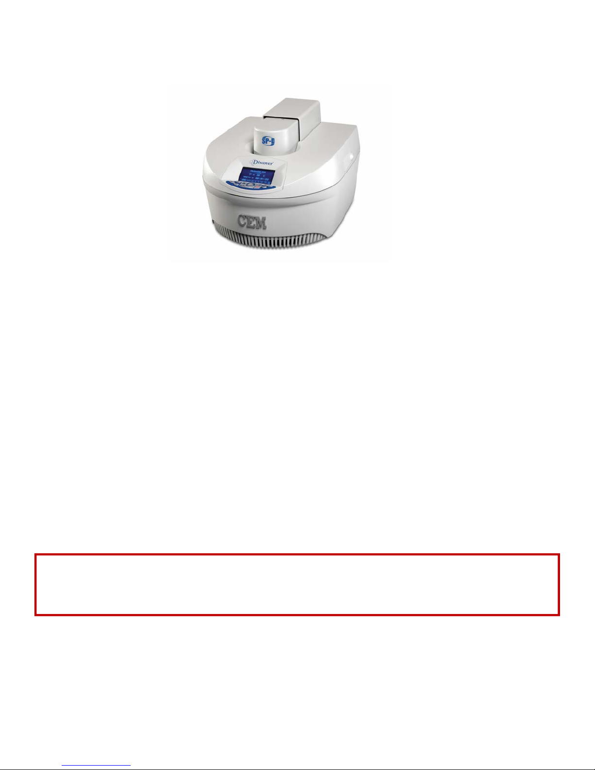
Instrument Description
Front View
User Interface
The user interface consists of the keypad and display which provide the means for the user to input information into and output
information from the Discover System.
The input functions are performed with the keypad and provide the ability to
● create new methods and edit existing methods,
● recall and delete methods,
● change operating parameters during method operation in real time,
● start, pause and stop operation,
● set up a computer (optional),
● configure the sensor options and system options,
● create and edit user profiles.
The output functions are obtained from the display and computer/ethernet port. The display provides visual information of the
keypad entry and permanently stored instrument information. The computer/ethernet port provides the option of using an
offboard PC to program the system and to collect data.
● Display - displays menus, method parameters and instrument status on a 256 x 128 graphics display.
● Keypad - allows the operator to create, edit, store and recall methods, start and stop methods and change
programmed parameters during operation.
● Attenuator - provides access to the instrument cavity while preventing microwave leakage during operation.
The attenuator can be installed or removed with a twist-lock action (no tools required).
Never modify the attenuator access port or insert metallic objects such as wire into the port. Serious microwave
leakage and/or electrical shock may result. The access port of the Discover SP-D Clinical is electrically grounded to
the microwave cavity and is designed to prevent leakage of microwave energy.
● Interlock Assembly - monitors mating of the attenuator to the cavity. If the attenuator is not properly installed,
the instrument will not deliver microwave power nor permit the system to operate.
WARNING
3
Page 8

Keypad
• HOME - Press to return to the main screen from any menu in the software. Within the System Setup portion of
the software, press this key to return to the previous menu.
• START/PAUSE - Press to start the current method or press during method operation to pause or suspend
operation. Pressing the key again will restart the method from the paused point.
• ENTER - Press to accept entries while editing or creating a method or in System Setup.
• DISCOVER - Press to load, save and create methods and review data. Pressing this key permits navigation
through and selection of program options.
• STOP - Press to stop any process. Pressing this key when performing a method will stop microwave radiation
and launch the cooling function. Pressing this key during the cooling cycle will abort the cooling cycle and return
the system to the home screen.
• ARROW - Press to navigate through method programming or System Setup steps.
• +/- Press to increase or decrease highlighted method parameters or to navigate through System Setup steps.
• POWER - Press this key to change the maximum applied microwave power setting prior to or during a method.
Use the +/- keys to increase or decrease the setting. If this key is pressed during a method, this does not stop or
pause the method but updates the setting in real time. The updated setting is not captured as part of the saved
method file in the method library.
• STIRRING - Press this key to change the stirring setting prior to or during a method. Use the +/- keys to toggle to
the appropriate setting (High, Medium, Low, Off). If this key is pressed during a method, this does not stop or
pause the method but permits changing the setting in real time. The updated setting is not captured as part of the
saved method file in the method library.
• COOLING - Press this prior to beginning a method or during a method to perform the cooling function. If this key
is pressed during a method, it does not stop or pause the method but updates the setting in real time. The
updated setting is not captured as part of the saved method file in the method library. If this key is pressed while
the instrument is idle, the PowerMax option appears.
• TEMPERATURE - Press this key to change the temperature setpoint before or during a method. Use the +/- keys
to increase or decrease the setting. If this key is pressed during a method, this does not stop or pause a method but
updates the setting in real time. The updated setting is not captured as part of the saved method file in the
method library.
• PRESSURE - Press this key to change the pressure set point prior to or during a method. Use the +/- keys to
increase or decrease the setting. If this key is pressed during a method, this does not stop or pause a method but
updates the setting in real time. The updated setting is not captured as part of the saved method file in the
method library.
• TIME - Press this key to change the time value during or after a method. Use the +/- keys to increase or decrease
the time setting. Pressing this key allows for real time changes to this value. This does not stop or pause a
method but updates the setting in real time.
Method Status Bar
4
Page 9
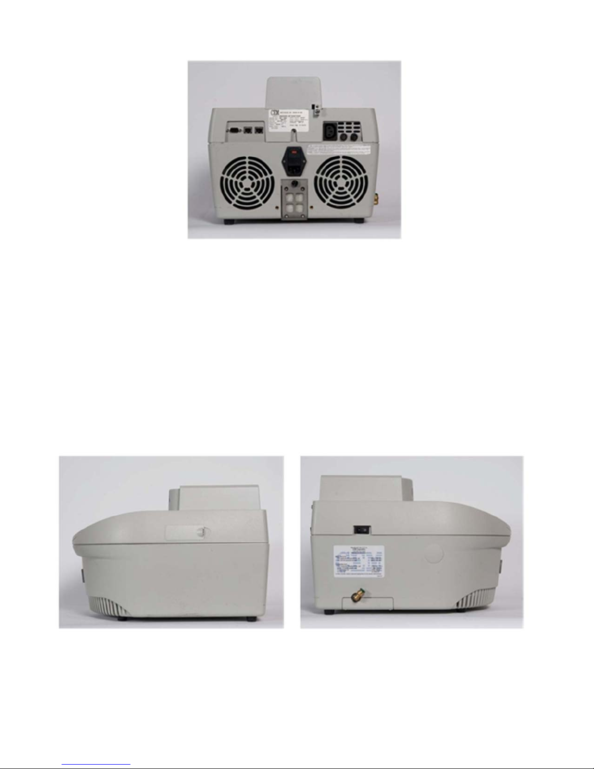
Rear View
Power Cord Receptacle - Receives the female end of the power cord.
Magnetron Cooling Fan - Draws room air past the magnetron for cooling purposes.
Power Supply Cooling Fan - Draws room air past the power supply for cooling purposes.
Fuses - Prevent electrical power overload.
Electrical Connector - Connects autosampler or other peripheral accessory to the reactor
module.
RS232 Port - Allows additional connection and communication.
Spill Tray - Removable collection tray for cavity contents in case of a vessel failure.
Ethernet Port - Allows communication and connection to an external computer for data collection,
a local area network (LAN) or the Internet. (Optional).
Nameplate - Lists the model, serial number, Product Tag, operating voltage, frequency and
current of the instrument.
Side Views
Power Switch - Turns AC power on and off to the instrument.
Cooling Gas Line - Provides a hose connection for the cooling gas source.
7-Pin Connector - Connects pressure measurement device to the main controller board.
USB Ports - Permit installation of USB flash drive to import, export, backup and/or save instrument data.
RJ 11 Port - Permits connection and use of additional accessories.
5
Page 10

Sample Stirrer
The sample stirrer is a plate containing electromagnetic coils positioned beneath the instrument cavity floor. The
electromagnetic stirring plate works in conjunction with stirring bars placed in the reaction vessel to affect stirring and
ensure a homogeneous sample. An initial supply of magnetic stir bars are provided with the system. Additional stir bars are
available from CEM Corporation. Commercial Teflon® coated magnetic stir bars can be used.
NOTE: The stir bars are Teflon®-coated iron oxide bars. When placed in the microwave field, the iron oxide bars will reflect
the microwave energy without damaging the instrument.
WARNING
Cardiac pacemakers require magnets to control operation during checkout. If the Discover System is equipped with a
sample stirrer, some danger exists if a pacemaker is positioned in close proximity to the instrument cavity. If the
instrument is suspected of interfering with the operation of a pacemaker, the instrument should be turned off or the
pacemaker wearer should move away from the instrument.
Cooling
The cooling feature directs a gas source onto the outside wall of the reaction vessel. This provides the ability to rapidly
cool (quench) a reaction after the application of microwave energy. The cooling feature is either on or off and is part
of the method. The feature consists of:
• plumbing to direct the gas from the inlet point of the Discover to the reaction vessel in the cavity, a solenoid
valve connected to the CPU (controller) board to turn the gas flow on and off,
• A hose fitting to connect the Discover to the gas source via hose, and
• 8 feet (2.44 meters) of 1/4 inch (6.35 mm) inside diameter air hose.
The gas source is user supplied. CEM Corporation recommends either nitrogen or clean air at a minimum pressure of 25 psi
(~ 1.5 bar). This will provide a flow rate of 20 liters per minute and will cool a 5mL volume of ethylene glycol in a 10mL reaction
vessel from 150°C to less than 50°C in less than 2 minutes.
6
Page 11

System Installation
Installation Site
The Discover System is designed for installation in a laboratory fume hood or on a laboratory bench with proper ventilation.
Choose a location that
provides at least 8 in. (20 cm) of open space on each side and 6 in. (15 cm) of open space in the rear of the
instrument for ventilation. The space should be at least 22 in. (46 cm) wide by 25 in. (64 cm) deep with a height
clearance of at least 35 in. (89 cm).
Is free from vibration of large equipment and/or excessive walk-through traffic.
provides a temperature range of 41 °F (5 °C) to 104 °F (40 °C) and a humidity range of ±10-85% relative humidity.
provides adequate space for sample handling (and computer placement if applicable),
permits the system to be connected to a dedicated, grounded 120 or 240 VAC outlet. The Discover System should be
operated on a stabilized, constant voltage AC power supply. To operate properly, the voltage must be within 10% of
specified level.
Unpacking
Carefully remove the system from its shipping carton and place it in an appropriate location in the fume hood or on a
laboratory bench.
Note: Retain all packing material for use if returning the system to the manufacturer, subsidiary or distributor for service.
Inspect the instrument for shipping damage such as cracks, dents or warping.
WARNING
Upon receipt, if damage to the instrument is noted, do not attempt to operate the instrument.
This instrument utilizes high voltages and microwave radiation. Only technicians trained in repair and maintenance
of high voltage and microwave power systems should perform instrument service and repair.
Never modify the attenuator access port or insert metallic objects such as wire into the port. Serious microwave
leakage and/or electrical shock may result. The access port of the instrument is electrically grounded to the
microwave cavity and is designed to prevent leakage of microwave energy.
Cardiac pacemakers require magnets to control operation during checkout. Because the Discover System is
equipped with a variable-speed, electromagnetic sample stirrer, some danger exists if a pacemaker is positioned in
close proximity to the instrument cavity. If the instrument is suspected of interfering with the operation of a
pacemaker, the instrument should be turned off or the pacemaker wearer should move away from the instrument.
Disconnect the instrument from the AC power source prior to performing any service procedure.
If the instrument has been damaged in shipping, contact the freight carrier to report the damage and to file a damage
report. Contact the CEM Service Department or the local subsidiary or distributor to report damage and to request
service information.
7
Page 12
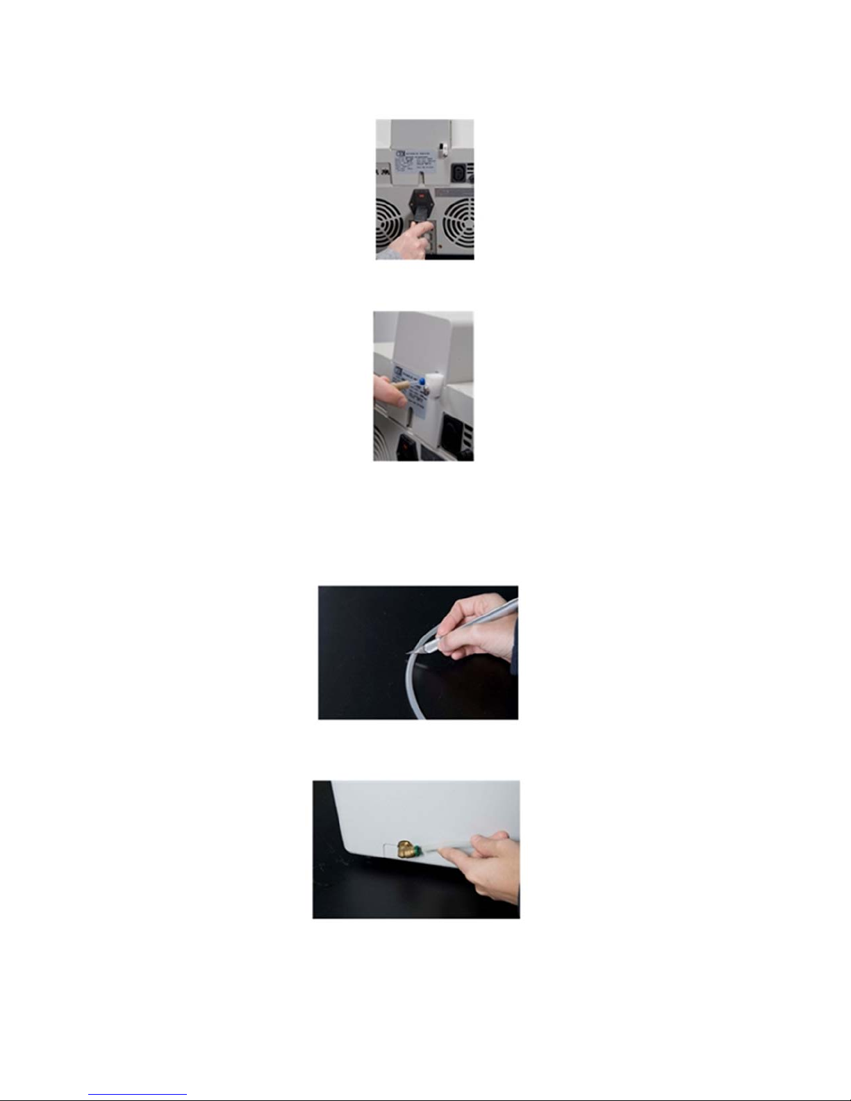
Discover SP-D Clinical Installation
1. Place the Discover in a hood or on bench.
2. Plug the power cord into the back of the instrument.
3. Remove the vent tubing from the accessory kit and connect to the rear of the ActiVent.
4. Place the other end in the back of the fume hood or other location appropriate for solvent exposure.
5. Plug the power cord into the wall outlet.
6. To set up the air regulator:
a. Splice the tubing supplied by CEM in half.
b. Install one length of the tubing into the left side of the Discover by pushing in on the tubing
until resistance is felt.
c. Place the opposite end of the tubing into the regulator.
8
Page 13
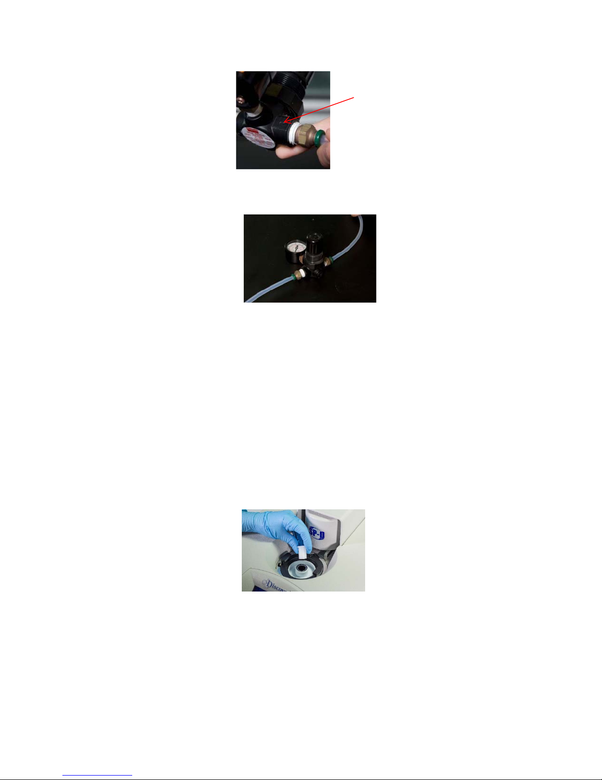
NOTE: The regulator has an arrow printed on it to show the direction that the air must flow. Set up the regulator according to
A
the arrow.
ir Flow Arrow
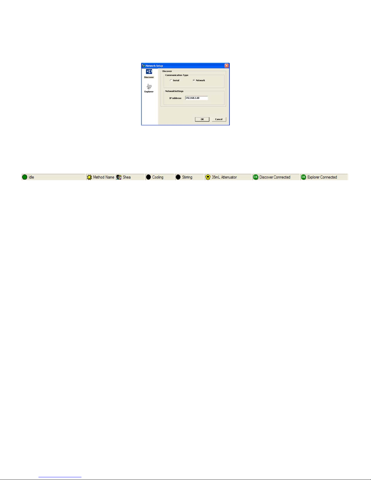
d. Place the second length of tubing into the opposite end of the regulator.
e. Connect the opposite end of the tubing to the air source.
f. To change the amount of air flow from the regulator:
Pull the knob on the regulator outward.
Rotate the knob clockwise to increase the amount of air flow.
Rotate the knob counterclockwise to decrease the amount of air flow.
The minimum compressed gas requirement is 25 PSI (20L/min flow).
The maximum flow rate is 60 PSI.
Note: The air flow should remain on at all times when a reaction is being performed.
7. Check the cavity for debris.
8. Using the power switch located on the left side of the Discover, turn the instrument on.
9. The ActiVent (pressure device) will return to the home position once the Login screen appears. Remove the 10mL
shipping device.
Note: Do not discard the 10mL shipping device. It will be required if returning the system to CEM Corporation for service.
Computer Installation (optional)
1. Connect one end of the Ethernet cable to one of the Ethernet ports located at the rear of the Discover.
2. Connect the opposite end of the Ethernet cable extending from the Discover to the computer.
3. Ensure that the computer is turned on and the desktop is visible. Select the Synergy icon to activate the Synergy
software. If the Synergy icon is not visible on the desktop, insert the Synergy CD and follow the on-screen
instructions.
Note: If this is the first time the software has been activated on the computer, the user will be prompted to create a new
account.
9
Page 14
4. Using the pull-down menu, select the proper name and enter the appropriate password. Select “OK.” Synergy will
automatically load the user’s preferences and connect to the Discover and Explorer modules during the login
process.
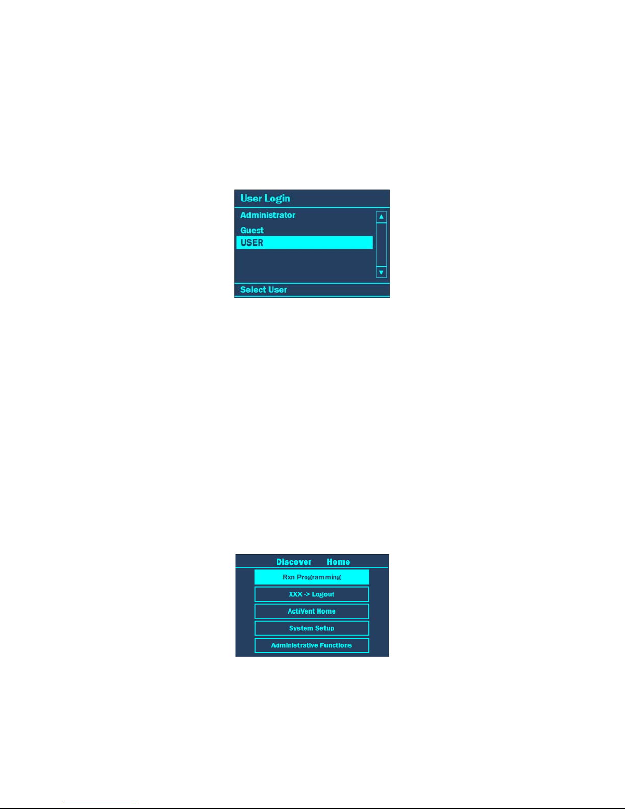
5. Select “Network Setup.” The following screen will appear.
6. Select the Discover icon.
7. The IP Address should read “192.168.1.60.” If the IP Address does not read as shown, highlight the IP Address, and
using the computer keyboard, enter the correct IP Address.
8. Select “OK.” The icons in the status bar will become green and show that the instruments are connected.
9. If the icons are red and the system is not connected, follow the procedure as outlined below to assign a fixed IP
Address to the PC/Laptop:
a. Right click the “My Network Places” icon on the desktop and select “Properties.” This will open the “Network
Connections” window.
b. Right click “Local Area Connection” and select “Properties.” This will open the “Local Area Connections
Properties” window.
c. Select the “General” tab; highlight the “Internet Protocol (TCP/IP) connection and select “Properties.” This will
open the Internet Protocol (TCP/IP) Properties 168.1.window.
d. Select “Use the following IP Address.”
e. Assign 192.168.1.10 to the IP Address.
f. Press the “tab” button. Tthe subnet mask box should populate with 255.255.255.0
NOTE: The IP address consists of up to 12 numeric characters. The address is broken into 4 sets of up to 3 numeric
characters per set. Each set is separated by a period (.). In the Discover System, the first character after a period can be
a zero (0). However the first numeric character cannot be a zero when entered into the PC/Laptop IP Address box. The
first two sets of Fixed IP Address numbers for the PC/Laptop must match the first two sets of numbers in the Discover IP
Address. However, the PC/Laptop’s Fixed IP Address must be unique, thus the reason to decrement the last set of
numbers.
g. Press the “OK” button. This will close the Internet Protocol (TCP/IP) Properties window and return the user to the
“Local Area Connections Properties” window.
h. Select the “close” button to return to the “Network Connections” window.
i. Close this window to return to the Desktop.
j. Follow the above steps 1 – 8.
10
Page 15
User Login
Before system operation can begin, the user is required to log into the Discover system. The Discover software is
designed to permit use by three types of users: Standard, Administrator and Guest. The Discover is originally equipped
with an “Administrator,” “User” and “Guest”. The “Administrator” login cannot be deleted. Refer to instrument setup for
instructions to create administrative, guest and standard user profiles.
Administrator- can add, modify, or delete users; perform tasks related to the maintenance of the
system; modify all system settings and perform methods.
Standard- can perform methods and modify all system settings.
Guest- can perform methods.
1. When the instrument is turned on, the “Login” screen will appear. Use the “+/-” keys to select the appropriate user.
2. Press ENTER.
3. If the user is prompted to provide a password:
a. Use the ARROW and “+/-” keys to highlight the first letter or number of the password.
NOTE: The “Shift” key changes the letters and/or symbols to lowercase.
b. Press ENTER to accept the first letter.
c. Continue highlighting the letters or numbers of the password and pressing the ENTER key for each
letter/number until the password has been entered.
d. Once the password is entered, use the ARROW and “+/-” keys to highlight “OK.”
e. Press ENTER to log in.
User Logout
Once system operation is complete, the user can log out of the system. If the system is idle for 20 minutes or longer, the
system will automatically go into an idle mode and the user will be required to log in to continue operation.
1. To log out, press HOME until the “Discover Home” screen appears.
2. Use the “+/-” keys to highlight “XXX-Logout.”
NOTE: The user name will appear where the “XXX” are located.
3. Press ENTER to log out.
11
Page 16

Microwave Tips
Cover all solids in the reaction vessel with liquid.
Never exceed the maximum working volume of the vial.
Always use a stir bar that adequately mixes the reaction contents in the microwave.
Reactions can be performed under an inert atmosphere.
Try performing the reaction at higher concentrations.
How to Cautiously Microwave
Start with a low power input - 200 W or less (this can be adjusted as necessary)
Watch the first minute of the reaction.
If a gas forms during the reaction, Cool the reaction completely. Allow the ActiVent to release the excess gas.
Standard Vessel
Total Volume/
Vessel Name
4 mL 0.200 – 2.0 mL Sealed
10 mL 0.200 – 5.0 mL Sealed
Working Volume Sealed/Pressurized or
Open/Atmospheric
12
Page 17

Closed Vessel Extraction
Items Required:
4mL/10mL Attenuator
4mL/10mL mL Vial
Stir bar appropriate for vial size
4mL/10mL Cap
Prepare the Vial
1. Select the vial based on the volume of solvents being used.
NOTE: The working volume for the 10mL vial is 0.2mL to 5mL. The working volume for the 4mL vial is 0.2mL to
2mL.
2. Place an appropriate stir bar into the vessel.
3. Place the reaction components into the vessel.
Proper precautions must be taken to avoid contact with acids or acid vapors. Protective gear should be worn as outlined
in the user’s safety program for hazardous materials and the reagent manufacturer’s material safety data sheet. Refer to
these guidelines for proper decontamination, handling and disposal of reagents or any hazardous materials.
4. Place the cap onto the vial.
The Discover SP-D Clinical is usable only with CEM supplied 4mL or 10mL reaction vessels and caps for sealed
reactions.
5. Install the appropriate attenuator assembly with the large slot positioned toward the back of the instrument.
6. Rotate the attenuator assembly clockwise until the attenuator locks into position.
7. Place the vessel into the attenuator.
Perform a Method
1. Load or create the appropriate method into the instrument on the Discover SP-D Clinical or the Synergy software
(see section “Load Method” or “Create New Method or the Synergy software “Help” text for creating a method).
2. Press the START/PAUSE key. The ActiVent will close and lock onto the vessel. The “Waiting” screen appears prior
to irradiation initiation. Once the method begins, the system ramps to set-point temperature. The system continues to
meet method parameters to perform the complete method.
NOTE: The information across the bottom of the screen displays the parameter status as follows:
Pressure (Bar or PSI)
Power (W)
Stirring (H {High}, M {Medium}, L {Low} or Off (X)
Temperature Control (IR {Infrared} or FO {Fiber Optic)}
Vessel Type - If the vessel is a sealed vessel, the size will be displayed beside the picture of the vessel.
Cooling (Off or On) - If Cooling is “on,” a snowflake is displayed.
Microwaves (Off, On)
System accessories (D {Discover}, or E {Explorer})
WARNING
WARNING
13
Page 18

Remove the Vessel
1. Once the vessel is properly cooled, the ActiVent will release the vessel and “Complete” will appear on the
Display. If the ActiVent does not automatically release the reaction vessel, the pressure (or temperature) is above the
release limit. A message will appear indicating the current temperature and pressure value. Cool the reaction vessel
completely and manually release the ActiVent.
2. Rotate the attenuator assembly counterclockwise and lift it from the instrument.
WARNING
To prevent the possibility of severe burns, wear insulated gloves and protective gear as outlined in the user’s safety
program.
3. Carefully remove the vessel from the attenuator.
NOTE: If the cap still holds residual pressure, place the cap and vial in a fume hood or other well-ventilated area.
Use a needle to pierce the septa to vent the pressure.
4. Remove the cap from the vessel by pressing upward on one side of the cap.
WARNING
Vessels and caps are designed for only one use. Do not use vessels and/or caps more than one time.
14
Page 19
Load, Save, and Create a New Method
The “Load, Save, and Create a New Method” screen allows all users to create new methods, save them to the Discover
data base and Load (recall) the methods at a later time. From this screen, the user can also recall data from a reaction
previously run on the Discover system. To access this screen press the Discover key on the Discover keypad.
Create a New Method
The Discover System has three (3) control options for programming a method – Standard, Dynamic and Ramp-toTemperature. These options permit the user to control how the system applies the microwave energy to the reaction.
In all control options, the user inputs control parameters to create the method. The user enters more control information
as the level of control increases. The Standard control option is the recommended control technique for routine operation.
The Dynamic method allows the user to implement the ActiVent feature. The SP-D Clinical system permits the user to
release unwanted gaseous byproducts from the reaction to prevent over pressurization and vial failure from gaseous
buildup. This ensures safe handling of the vial during and at the end of the reaction. The ActiVent safely bleeds the
solvent/vapor from the reaction vessel and releases it through the vent tube connected to the back of the system and into
a controlled environment.
If the reaction generates a gaseous byproduct or an extreme amount of pressure during the reaction, the ActiVent will
vent at a specific set point for a pre-determined number of times.
• The “Delta Pressure” is the assigned amount of pressure to drop from the pressure set point. A delta of 50 PSI
(1.7 BAR) is recommended.
• The “PressureSP” is the pressure set point at which the venting will begin. If the gaseous byproduct that is
generated is the only pressure in the reaction vial (the reaction temperature does NOT exceed the boiling point of
the solvent), the ActiVent pressure release can be set below the control point. If a gas is generated, but some of
the pressure is due to vapor pressure, then the release point for the ActiVent must be set at or above the
pressure control point.
• The “Times at SP” is the maximum number of times a reaction will vent during the assigned ramp and hold time.
However, this parameter can be adjusted based on specific reaction conditions. For a typical reaction, 5 vents
are recommended.
CAUTION
If the reaction temperature exceeds the acid boiling point and too many venting actions are performed, the vial
could become dry and superheat.
• The number of stages is the stage at which the PressureSP will be active for a multistage method. A maximum of
5 stages can be added.
15
Page 20

Standard
The Standard Control is a fast and simple reaction method. The user programs
A temperature control point and
A run time (time held at the specified temperature).
All other method parameters are controlled by the instrument defaults. All method parameters can be edited with the
Discover hotkeys.
1. With the main menu displayed, press the DISCOVER key.
2. Using the ARROWS and “+/-” keys highlight “Standard.”
3. Press the ENTER key.
4. Press the temperature hotkey on the Discover keypad to modify the method.
5. Use the “+/-” keys to increase or decrease the temperature to the desired parameter. (0 - 220°C)
6. Press the right ARROW key to highlight “Time”.
7. Use the ARROW keys to select the hours, minutes, and/or seconds of time to edit. Use the “+/-” keys to increase
or decrease the selected time parameter. (1 second to 99 hours, 59 minutes and 59 seconds).
8. Once the time is entered properly, press the ENTER key to accept all method parameters.
Dynamic
The Dynamic Control option provides more flexibility in how the user programs a reaction method. It applies to a
specified amount of power, defined by the user, to reach the control point. It modulates this set power automatically,
based on the sensor feedback data, to ensure the control point is reached rapidly, but with limited error (temperature or
pressure “overshooting”). The user programs:
the maximum amount of microwave power that can be applied to the method,
a temperature control point,
a pressure control point,
a hold time (the time the system maintains the control parameters),
a stirring function with speed control and a pre-stir option, and
PowerMAX (simultaneous cooling).
The ActiVent feature can be implemented in Dynamic Control. If the reaction generates a gaseous byproduct or an
extreme amount of pressure during the reaction, the ActiVent will vent at a specific setpoint for a pre-determined number
of times.
The “Delta Pressure” is the assigned amount of pressure to drop from the pressure set point. A delta of
50 PSI (1.7 BAR) is recommended.
The “PressureSP” is the pressure set point at which the venting will begin. If the gaseous byproduct that
is generate is the only pressure in the reaction vial (the reaction temperature does NOT exceed the
boiling point of the solvent), the ActiVent pressure release can be set below the control point. If a gas is
generated, but some of the pressure is due to vapor pressure, the release point for the ActiVent
must be set at or above the pressure control point.
16
Page 21

The “Times at SP” is the maximum number of times a reaction will vent during the assigned ramp and
hold time. However, this parameter can be adjusted based on specific reaction conditions. For a typical
reaction, 5 vents are recommended.
CAUTION
If the reaction temperature exceeds the acid boiling point and too many venting actions are performed, the vial
could become dry and superheat.
The number of stages is the stage at which the PressureSP will be active for a multistage method. A
maximum of 5 stages can be added.
The Dynamic Control option can be programmed for three (3) stages for multiple irradiation steps and is a general control
method for maintaining critical control points.
1. With the main menu displayed, press the DISCOVER key.
2. Using the ARROWS and “+/-” keys highlight “Dynamic”.
3. Press the ENTER key.
4. Press one of the hotkeys to modify any of the default parameters.
5. Use the ARROW keys to navigate between temperature, time, power, pressure, stirring, PreMix, PowerMAX and
number of Stages to enter the desired method parameters. Use the “+/-” keys to increase and decrease the
numeric value.
Temperature - 0 - 220 °C
Time - 1 second to 99 hours, 59 minutes and 59 seconds
Power - 0-300W (150W recommended)
Pressure - 0-400 PSI or 0-21Bar (250PSI recommended)
Stirring - “high”, “medium”, “low” and “off” (High recommended)
PreMix - fifteen-second increments up to 120 seconds
PowerMAX - “on” or “off”
Stage - 1-5 stages
17
Page 22

6. Press the DISCOVER key to activate and program parameters for the ActiVent option. If the ActiVent feature is
not being used, proceed to step 8.
CAUTION
If the reaction temperature exceeds the acid boiling point and too many venting actions are performed, the vial
could become dry and superheat.
NOTE: The ActiVent feature is not required for the Dynamic Control Option. It allows the Discover SP-D Clinical System
to release unwanted gaseous byproducts from the reaction to prevent over pressurization and vial failure from gaseous
buildup.
NOTE: If the ActiVent feature is not being used, the system will automatically release excess pressure above 400 Psi or
21 Bar.
7. Enter the desired vent parameters using the ARROW keys to navigate between Delta Pressure, Stage, PressureSp,
and Times @ SP. Use the “+/-” keys to increase and decrease the numeric value(s).
The “Delta Pressure” is the assigned amount of pressure to drop from the pressure set point. A delta of 50 PSI
(1.7 BAR) is recommended.
The “PressureSP” is the pressure set point at which the venting will begin. If the gaseous byproduct that is
generated is the only pressure in the reaction vial (the reaction temperature does NOT exceed the boiling point of
the solvent), the ActiVent pressure release can be set below the control point. If a gas is generated, but some of
the pressure is due to vapor pressure, then the release point for the ActiVent must be set at or above the
pressure control point.
The “Times at SP” is the maximum number of times a reaction will vent during the assigned ramp and hold time.
However, this parameter can be adjusted based on specific reaction conditions. For a typical reaction, 5 vents
are recommended.
The number of stages is the stage at which the PressureSP will be active for a multistage method. A maximum of
5 stages can be added.
8. Once all ActiVent parameters have been entered, press the ENTER key to return to the method parameters screen.
9. Press the ENTER key to accept all method parameters.
Ramp-to-Temperature
The Ramp to Temperature Control option is the RECOMMENDED control type for all digestion samples. The sample is
brought to temperature in an exact programmed time, and power is varied automatically to follow that time. The effects of
variations in sample absorbance characteristics are minimized as each sample runs the same temperature profile. The
user programs:
the ramp time to achieve the temperature
the hold time at that temperature
the input power level
a control temperature (the temperature at which the magnetron will turn off)
a maximum pressure (the maximum pressure the Discover SP-D Clinical will control at or below)
stirring speed (stirring is required for digestions). CEM Corporation recommends medium speed.
a premix time (time for stirring before the heating begins)
18
Page 23

1. With the main menu displayed, press the DISCOVER key.
2. Using the ARROWS and “+/-” keys highlight “Ramp to Temp”.
3. Press the ENTER key.
4. Press a ‘HOT KEY’ (T or P).
5. Enter the desired method parameters using the “arrow” keys to navigate between power, time, temperature, pressure
stirring and PreMix. Use the “+/-” keys to increase and decrease the numeric value.
• Ramp “Time”- 1 second to 99 hours, 59 minutes and 59 seconds
• Hold “Time”- 1 second to 99 hours, 59 minutes and 59 seconds
• Power “μλ”- 0-300W
• Temperature “To”- 15-260 ºC
19
Page 24

• Pressure ‘P’ – 0 – 500PSI
• Stirring Speed – Low, Medium, High (Medium is recommended). Stirring is required for digestions.
• PreMix Time – 0-120 seconds
6. Press the Discover key to activate and program parameters for the ActiVent® option and select the vessel type.
NOTE: The ActiVent feature is REQUIRED for the Ramp to Temperature Control Option. It allows the Discover to release
unwanted gaseous byproducts from the reaction to prevent over pressurization and vial failure from gaseous buildup.
NOTE: If the ActiVent feature is not set, the system will automatically release excess pressure above 500PSI or 35Bar.
Select or change the Vessel Type – Vessel or Vessel with Liner.
7. Enter the desired vent parameters using the “arrow” keys to navigate between Delta pressure, Stage, PressureSP,
and Times @ SP. Use the “+/-” keys to increase and decrease the numeric value.
The “Delta Pressure” is the assigned amount of pressure to drop from the pressure set point before reclosing. A
minimum delta of 50 PSI (3.45 BAR) for 4 mL and 10 mL vessels is recommended.
• The “PressureSP” is the pressure set point at which the venting will begin. The pressure vent setpoint should be
set at a value appropriate for the sample type and size.
• The “Times at SP” is the maximum number of times a reaction will vent during the assigned ramp and hold time
at that vent point. This parameter should be adjusted based on specific reaction conditions.
• The number of stages is the stage at which the PressureSP will be active for a multistage method. A maximum of
5 stages can be added.
8. Once all parameters have been entered, press the ENTER key to return to the method parameters screen.
9. Press the ENTER key again to accept all method parameters.
Save a Method
Saving a method allows the user to save/store the method so it can be recalled later. There are two (2) options to save a
Method: (a) press the DISCOVER key, highlight “Save” and press the ENTER key or (b) press the start key after
programming a new method.
NOTE: A method can be created and used without being saved. If not saved, once the method has been used, but before
any modifications are made to the screen, the method can be saved using the (a) procedure outlined above.
NOTE: All of the current user’s methods can be saved to a USB device and transferred to another instrument or placed
on a personal computer. Refer to the section titled “Back Up Methods” for additional information.
After programming a new method, when the Start key is pressed, the user is given the option to save or not save the
method that is currently set to start. If “No” is selected, the method that was just created will be sent to the Discover and
the reaction will begin. If “Yes” is selected, the method will be saved and the reaction will start immediately after the
method has been saved.
1. Create a new method (refer to section “Create New Method”).
20
Page 25

2. Choose one option to save the method:
a. Press the DISCOVER key, highlight “Save” and press the ENTER key.
b. Press the Start key after a new method has been created.
3. A new screen will appear. Use the ARROW and “+/-” keys to highlight the first letter or number of the desired
method name.
NOTE: “Shift” changes the letters and/or symbols to lowercase.
4. Press the ENTER key to accept the first letter.
5. Continue highlighting the letters or numbers of the name and pressing the ENTER key for each letter/number until
the name is displayed on the screen.
6. Once the method name has been entered, use the ARROW and “+/-” keys to highlight “OK.” The method will be
saved to the current user’s database.
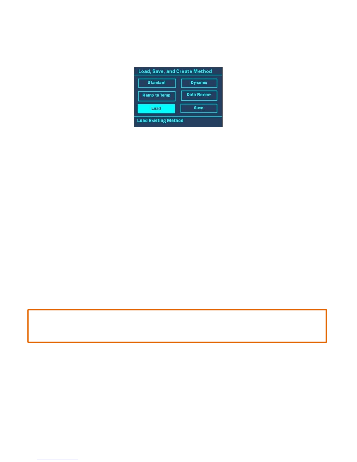
Load Method
The Load Method option gives the user the ability to recall a method previously saved under their user profile or that of
another user saved on the same Discover SP-D Clinical System. Methods can also be transferred from one system to
another using the USB flash drive supplied with the Discover SP.
1. With the main menu displayed, press the DISCOVER key.
2. Using the ARROWS and “+/-” keys, highlight “Load”.
3. Press the ENTER key.
4. The current user’s methods will be displayed. Use the “+/-” keys to highlight the desired method to load into the
system.
5. Press the ENTER key to load the method.
NOTE: To load a method stored for another user:
1. Use the “+/-” keys to highlight the user’s name.
2. Once the user name is highlighted, press the ENTER key.
3. Use the “+/-” keys to highlight the desired method.
4. Press the ENTER key to load the method.
NOTE: The method can be saved in the user’s folder by using the “Save” feature.
19
21
Page 26

NOTE: To load a method stored on the USB flash drive:
1. Insert a USB device with stored methods into the side of the system. Refer to the section titled “Backup Methods” for
information on how to save methods onto the USB device.
2. Press the DISCOVER key.
3. Press the “+/-” keys to highlight “Load.”
4. Press the ENTER key.
5. Use the “+/-” keys to scroll through the list until the desired user is highlighted.
6. Press the ENTER key to display the user’s methods.
7. Use the “+/-” keys to highlight the desired method.
8. Press the ENTER key to load the method.
9. The main menu is displayed with the loaded method’s name in the title bar.
Data Review
If the USB drive is in position on the side of the Discover during the reaction, the temperature data for each run will
automatically be stored. This data can be viewed on the Discover screen later as a graph or viewed as individual data
points on a computer.
NOTE: Only USB flash drives supplied by CEM Corporation are compatible with the Discover SP-D Clinical system.
1. Install the USB flash drive containing the desired method data for review.
2. With the main menu displayed, press the DISCOVER key.
3. Using the ARROW and “+/‐” keys, highlight “Data Review.”
4. Press the ENTER key.
5. Use the “+/-” keys to highlight the user for which the data is to be reviewed.
6. Press the ENTER key.
7. Use the “+/-” keys to highlight the data to be viewed.
8. Press the ENTER Key. A graph will appear on the screen with a temperature curve.
22
Page 27

NOTE: The Synergy Software provides a more detailed record of the reaction, including information such as
power and pressure data in addition to the temperature data.
9. Press the “Home” key twice to return to the Main Menu.
NOTE: The data file can be graphed on a computer as a CSV file.
1. Install the USB drive containing the reaction data into the computer.
2. Select the “CEM” folder.
3. Select the appropriate user’s folder.
4. Select the “data” folder.
5. Select the appropriate data file and open as a CSV or excel document.
Delete Method
The Delete Method function allows the user to delete methods that have been stored within the Discover SP-D Clinical
database.
1. With the main menu displayed, press the DISCOVER key.
2. Using the ARROWS and “+/-” keys, highlight “Load.”
3. Press the ENTER key. The current user’s methods will be displayed.
4. Use the “+/-” keys to highlight the desired method to be deleted.
5. Press the right ARROW key.
6. Use the ARROW keys to highlight “Delete”.
23
Page 28

7. Press the ENTER key.
8. Use the ARROW keys to highlight “Yes” or “No”.
9. Press the ENTER key. If “yes” was selected the method will be permanently deleted. If “No” is selected the
previous screen will appear.
Discover Home
The Discover home screen allows the users to set operations parameters within the Discover firmware. The Discover
firmware is designed to permit use by three types of users: Standard, Administrator and Guest. A Guest can perform
methods. A Standard User can perform methods and modify all system settings. An Administrator can add, modify, or
delete users; perform tasks related to the maintenance of the system; modify all system settings and perform methods.
The Discover includes three users when shipped:
Administrator (includes all administrator privileges and is password protected
USER (includes all administrator privileges and does not include a password)
Guest (includes Guest privileges)
If the Discover is not being installed by a CEM representative, contact CEM to obtain a password that will permit
administrative rights.
The Discover Home screen will appear differently for users according to their user type: Guest, Standard, and
Administrator.
Guest Standard Administrator
Rxn Programming
The Reaction Programming screen allows the user to return to the main menu screen. The user can also press the
HOME key to return to the main menu.
NOTE: “Rxn programming” can be viewed by all user types (guest, standard, and administrator).
1. To view the “Discover Home” screen press the HOME key.
2. Use the “+/-” keys to highlight “Rxn Programming.”
3. Press the ENTER key. The main menu screen will appear.
24
Page 29

Logout
Once system operation is complete, the user can log out of the system. If the system is idle for 20 minutes or longer, the
system will automatically go into an idle mode and the user will be required to login to continue operation.
NOTE: “Logout” can be viewed by all user types (guest, standard, and administrator).
1. To logout, press the HOME key until the “Discover Home” screen appears.
2. Use the “+/-” keys to highlight “XXXX-Logout.”
NOTE: The username will appear where the “XXXX” is located.
3. Press the ENTER key to log out.
ActiVent Home, ActiVent Moving, ActiVent Closed, APM Recovery
There are four (4) different messages that can appear in the 3rd line of the Discover Home screen. Each message
describes the position of the ActiVent (APM).
NOTE: “ActiVent Home, ActiVent Moving, ActiVent Closed, APM Recovery” can be viewed by all user types (guest,
standard, and administrator).
• ActiVent Home is displayed when the attenuator is exposed and the APM is near the back of the instrument.
When “ActiVent Home” is highlighted and the ENTER key is pressed, the ActiVent will move to the closed
position. If a vessel is not in place when the ENTER key is pressed, the Discover SP-D Clinical will display a
“Vessel Not Found” message.
• ActiVent Moving is displayed when the ActiVent is either going to the home or closed position.
• ActiVent Closed is displayed when the ActiVent is positioned over the attenuator and the vessel is sealed. If
“ActiVent Closed” is highlighted and the ENTER key is pressed, the ActiVent will move to the home position.
• APM Recovery is displayed if the ActiVent is unable to find the home position. If “APM Recovery” appears, first
try to home the ActiVent. To home the ActiVent:
1. Use the “+/-” keys to highlight “APM Recovery”.
2. Press the ENTER key. A new screen will appear with the current error message.
3. Use the ARROW keys to highlight “APM Recovery”.
25
Page 30

4. Press the ENTER key. A new screen will appear.
5. Use the ARROW and “+/-” keys to highlight the “HOME” button.
6. Press the ENTER key. The APM will return to the HOME position.
CAUTION
Improper use of the APM Recovery screen could result in destruction of the APM, making the warranty null and
void.
The pressure assembly needs to be in the highest position before the APM is moved to the back of the
instrument.
7. If the APM does not return to the home position:
a. Follow steps 3-5 above.
b. Use the ARROW and “+/-” keys to highlight “Z UP.” Press the ENTER key. If the motor can be
heard, continue to select “Z Up” until the motor no longer sounds like it is turning. This will raise
the ActiVent to the highest position.
c. Use the ARROW and “+/-” keys to highlight “APM Back.”
d. Press the ENTER key. If the APM appears to be moving backward, select “APM Back” until the
ActiVent no longer moves backward. The ActiVent should be all the way back, away from the attenuator.
e. Use the ARROW and “+/-” keys to highlight the “HOME” button.
f. Press the ENTER key. The APM should now return to the HOME position.
System Setup
The “System Setup” function consists of five (5) “pages” that allow the user to calibrate system settings, set method
defaults, clean the ActiVent feature, and view system information.
NOTE: “System Setup” can only be viewed by Standard and Administrator users.
To enter the System Setup screen:
1. Press the HOME key until the “Discover Home” screen appears.
2. Use the “+/-” keys to highlight “System Setup”.
3. Press the ENTER key. A new screen will appear.
26
Page 31

User Setup
The “User Setup” page is the 1
st
page that appears after selecting “System Setup” from the Discover home screen. This
page allows the user to set up method defaults and general operating parameters for the Discover SP-D Clinical system.
Temperature Type
“Temperature Type” allows the user to switch between the Infrared and Fiber Optic temperature control.
1. Using the “+/-” keys, highlight “Temperature Type.”
2. Press the ENTER key.
3. Using the “+/-” keys, highlight the applicable temperature control to be utilized (infrared or fiber optic).
NOTE: To utilize the fiber optic control, the fiber optic temperature control option must be connected on the side of the
instrument. The part number for the fiber optic assembly is 541166.
4. Press the ENTER key. The “User Setup” screen will appear again.
Release limits
Temperature and pressure release limits are the temperature and pressure at which the ActiVent will
automatically open and release the vessel after cooling. The recommended default temperature is 60°C. The
recommended default pressure is 2.8 Bar (40 PSI).
NOTE: The default temperature should be lowered if a solvent with a low boiling point is used.
1. Using the “+/-” keys, highlight “Release Limits.”
2. Press the ENTER key.
3. Use the “+/-” keys to increase and decrease the release limits. Use the ARROW keys to toggle between
“Temperature” and “Pressure.”
4. Once the parameters have been entered, press the ENTER key. The “User Setup” screen will appear.
27
Page 32

User Profiles
The User Profiles option allows the user to set defaults when creating methods, edit/change the password and edit
system parameters. There are 4 pages within the “User Profiles” page.
1. From the “User Setup” screen, use the “+/-” keys to highlight “User Profiles.”
2. Press the ENTER key.
User Profiles
The “User Profiles” screen is the 1
st
page of the “User Profiles” menu. This page allows the user to clear or change
the password.
Clear Password
1. Use the “+/-” keys to highlight “Clear Password.” The user will be prompted to clear the password - yes or no.
2. Use the ARROW keys to highlight either “Yes” to clear the password or “No” to leave the password as is.
3. Press the ENTER key.
Change Password
1. Use the “+/-” keys to highlight “Change Password.” A new screen will appear.
2. Use the ARROW and “+/-” keys to highlight the first letter or number of the password.
NOTE: The “Shift” key changes the letters and/or symbols to lowercase.
3. Press the ENTER key to accept the first letter.
4. Continue highlighting the letters or numbers of the password and press the ENTER key for each letter/number until
the password has been entered.
5. Once the password is entered, use the ARROW and “+/-” keys to highlight “OK.”
User Profile Defaults -1
“User Profile Default” is the 2
nd
page of the “User Profile” menu. The “User Profile Defaults” page allows the user to
program a default Hold Time, Ramp Time, Temperature and Microwave Power.
Hold Time
“Hold Time” is the default amount of time defined by the user for the instrument to maintain the control temperature or
pressure. The instrument default hold time is five (5) minutes. When creating a new method, the hold time can be
changed from the default hold time programmed in the “User Profiles.”
1. Use the “+/-” keys to highlight hold time.
2. Press the ENTER key.
3. Use the ARROW keys to toggle between hours, minutes and seconds. Use the “+/-” keys to increase and decrease
the hold time (0 - 99 hours, 59 minutes, 59 seconds).
4. Press the ENTER key to accept the default hold time.
28
Page 33

Ramp Time
“Ramp Time” is the default amount of time defined by the user for the instrument to reach the temperature or pressure.
The instrument default ramp time is ten (10) minutes. The Discover System will achieve the set temperature as fast as
possible. The ramp time is a maximum amount of time that power will be applied before switching to the hold time. When
creating a new method, the ramp time can be changed from the default ramp time programmed in the “User Profiles.”
1. Use the “+/-” keys to highlight “Ramp Time.”
2. Press the ENTER key.
3. Use the ARROW keys to toggle between hours, minutes and seconds. Use the “+/-” keys to increase and decrease
the hold time (0 - 99 hours, 59 minutes, 59 seconds).
4. Press the ENTER key to accept the default ramp time.
Temperature
“Temperature” is the user defined control temperature. The default temperature is 125°C. When creating a new method,
the temperature can be changed from the default temperature programmed in the “User Profiles.”
1. Use the “+/-” keys to highlight “Temperature.”
2. Press the ENTER key.
3. Use the “+/-” keys to increase and decrease the temperature from 0-220°C.
4. Press the ENTER key to accept the default temperature.
Power
Microwave power is the user defined maximum power used during a method. The default microwave power is 150 watts.
When creating a new method the microwave power can be changed from the default power programmed in the “User
Profiles.”
1. Use the “+/-” keys to highlight “Temperature.”
2. Press the ENTER key.
3. Use the “+/-” keys to increase and decrease the microwave power from 0-300 watts.
4. Press the ENTER key to accept the default microwave power.
User Profile Defaults- 2
From the 1
screen. This is also the 3
st
“User Profile Default” screen, press the right arrow key one time to access the 2nd “User Profile Default”
rd
page of the “User Profile” menu. This page allows the user to program default Stirring, Pre-Mix
Time, Pressure and Pressure Units.
Stirring
“Stirring” is the user defined stirring speed for the method. The default stirring speed is high (this is also the recommended
speed when performing reactions in the 10 mL vials). When creating a new method the stirring speed can be changed
from the default stirring programmed in the “User Profiles.”
1. Use the “+/-” keys to highlight “Stirring.”
2. Press the ENTER key.
3. Use the “+/-” keys to increase and decrease the stirring between “High,” “Med,” “Low” and “Off”.
4. Press the ENTER key to accept the default stirring speed.
29
Page 34

Pre-Mix Time
“Pre-Mix Time” is the user-defined time for the stirrer to mix (stir) the sample prior to the ramp time. The default pre-mix
time is 0 seconds. The “Pre-Mix Time” can be edited only when creating a Dynamic method. The pre-mix time default that
is created in the “User Profile” is the time that will always be used when running a reaction in the remainder of the method
types.
1. Use the “+/-” keys to highlight “Pre-Mix Time.”
2. Press the ENTER key.
3. Use the “+/-” keys to increase or decrease the “Pre-Mix Time” by 15-second intervals between 0 and 120 seconds.
4. Press the ENTER key to accept the default pre-mix time.
Pressure
“Pressure” is the user defined maximum control pressure. The default pressure is 250 PSI or 17.2 Bar. When creating a
new method, the pressure can be changed from the default pressure programmed in the “User Profiles.”
1. Use the “+/-” keys to highlight “Pressure.”
2. Press the ENTER key.
3. Use the “+/-” keys to increase and decrease the pressure from 0 -400 PSI or 0-20 Bar.
4. Press the ENTER key to accept the default pressure.
Pressure Units
“Pressure Units” is the user-defined unit in which the pressure is displayed. The instrument default pressure unit is “PSI.”
1. Use the “+/-” keys to highlight “Pressure Units.”
2. Press the ENTER key.
3. Use the “+/-” keys to change the units between “PSI” and “Bar.”
4. Press the ENTER key to accept the default pressure unit.
User Profile Defaults - 3
From the 2
screen. This is also the 4
nd
“User Profile Default” screen, press the right arrow key one time to access the 3rd “User Profile Default”
th
and final page of the “User Profile” menu. This page allows the user to program the Key Beep,
Clock Format, and Cooling Time feature.
Key Beep
“Key Beep” is the option to turn on an audible beep that will sound each time a key on the keypad is depressed. The key
beep default setting is “On.”
1. Use the “+/-” keys to highlight “Key Beep.”
2. Press the ENTER key.
3. Use the “+/-” keys to change the key beep “On” or “Off.”
4. Press the ENTER key to accept the key beep option.
Clock Format
“Clock Format” allows the user to set the clock format in 12-hour or 24-hour increments. The default clock format is “12
Hour.”
1. Use the “+/-” keys to highlight “Clock Forma.t”
2. Press the ENTER key.
3. Use the “+/-” keys to change the clock format between “12 Hour” and “24 Hour.”
4. Press the ENTER key to accept the clock format.
30
Page 35

Cooling Time
“Cooling Time” is the user defined maximum time for the vessel to cool prior to removal. The default cooling time is 20
minutes. The “Cooling Time” cannot be edited/changed when creating a new method. The cooling time default that
created in the “User Profile” is the maximum time used when cooling a reaction. Should the reaction reach the predetermined release limits prior to the cooling time, the cooling stage will stop.
1. Use the “+/-” keys to highlight “Cooling Time.”
2. Press the ENTER key.
3. Use the “+/-” keys to change the cooling time from 0-60 minutes.
4. Press the ENTER key to accept the cooling time.
Backup Methods
“Back Up Methods” backs up the methods of the current user. These methods can be transferred to another instrument or
placed on a personal computer.
1. Install a CEM supplied USB flash drive into the right side of the Discover system.
2. Use the “+/-” keys to highlight “Backup Methods.”
3. Press the ENTER key. If a USB flash drive is installed in the USB port, a screen appears indicating the percentage of
the files backed up on the USB flash drive. Once all user methods are backed up, the software returns to the User
Setup screen.
NOTE: If a USB flash drive is not installed in one of the USB ports, the software will prompt the user to install a USB flash
drive. If desired, press the “Home” key to exit the screen.
CAUTION
Do not remove the USB flash drive from the USB port during method backup or restoration. Removal of the USB
flash drive prior to completion of method backup or restoration will corrupt the data on the USB flash drive
and/or the system files. Wait 15 - 20 seconds after the completion of method backup or restoration prior to
removal of the USB flash drive.
Restore Methods
“Restore Methods” transfers “backed up” methods and information from the USB flash drive to the system file.
1. Install a CEM supplied USB flash drive into the right side of the Discover system.
2. Use the “+/-” keys to highlight “Restore Methods.”
3. Press the ENTER key. If a USB flash drive is installed, a screen appears indicating the percentage of the methods
restored on the USB flash drive. Once all methods are restored, the software returns to the User Setup screen.
NOTE: If a USB flash drive is not installed in one of the USB ports, the software will prompt the user to install a USB
flash drive as indicated above.
Calibration Setup
The “Calibration Setup” page is the 2
screen. This screen allows the user to calibrate or enter a calibration value for the temperature and pressure controls.
nd
page that appears after selecting “System Setup” from the “Discover Home”
31
Page 36

Temperature
Temperature allows the user to calibrate or enter the slope for the infrared (temperature device). The user can also enter
the slope for the fiber optic, if applicable.
4. Using the “+/-” keys to highlight “Temperature.”
5. Press ENTER.
Infrared
Infrared allows the user to calibrate or enter the slope for the infrared temperature control. This is the first screen
To appear after “Temperature” has been selected from the “Calibration Setup” screen.
1. From the “Temperature Calibration” screen, use the “+/-” keys to select “Infrared.”
2. Press the ENTER key to enter the “IR Calibration” screen.
Slope
Slope is used to enter a known slope for the Infrared temperature control.
1. Use the “+/-” keys to highlight “Slope”
2. Press the ENTER key.
3. Use the “+/-” keys to highlight “Clr” to delete the current value.
4. Use the ARROW and “+/-” keys to highlight and select the proper number.
5. Continue highlighting the appropriate numbers and pressing the ENTER key to accept the values.
6. Once the slope has been entered, use the ARROW and “+/-” keys to highlight “OK.”
7. Press the ENTER key to complete the IR slope entry.
32
Page 37

Fiber Optic
If applicable, the Fiber Optic menu allows the user to enter the slope for the fiber optic probe.
Slope
“Slope” allows the user to enter the slope for the fiber optic probe.
1. To set up the Fiber Optic option:
a. Remove the cover from the right side of the Discover. Removal of the cover will expose 2 USB ports, 1
8-pin port, and 1 RJ-11 port.
b. To change the communication cable (if applicable):
1) Remove the gray communications cable (119750) from the fiber optic box by using a flat blade screwdriver to
loosen the two screws and then pull the cable away from the box.
2) Install the white communications cable (277275) to RJ-12 adapter (277225), by pushing in until a click is
audible.
3) Install the adapter to the fiber optic box and tighten the screws finger tight. (Refer to the Fiber Optic
Instructions for further information.)
c. Insert the temperature sensor into the temperature control module. The sensor is attached to the module with a
locking “collar” on the sensor. Push the collar in, rotate it clockwise, and then release it to lock the sensor into the
module.
d. Position the temperature control module on the right side of the Discover SP-D Clinical System (facing the front
of the instrument) and connect the communications into the RJ-11 port on the side of the Discover.
33
Page 38

2. To enter the GIF value:
a. From the “Temperature Calibration” screen, use the “+/-” keys to highlight “Fiber Optic.”
b. Press the ENTER key. A new screen will appear.
c. Use the “+/-” and ARROW keys to highlight “Clr” to clear the current slope.
d. Press the ENTER key to clear the contents.
e. Use the ARROW and “+/-” keys to highlight and select the GF Number (found on the label attached to the fiber
optic probe or the label on the case in which the probe was shipped).
f. Continue highlighting the appropriate numbers and pressing the ENTER key to accept the values.
g. Highlight “OK” when all numbers are entered.
h. Press the ENTER key.
Pressure (4mL and 10mL APM)
Only CEM Service Technicians should perform Pressure calibration of the Discover SP-D Clinical.
Network Setup
The “Network Setup” page is the 3
rd
page that appears after selecting “System Setup” from the “Discover Home” screen.
This page allows the user to view or enter an IP Address, Sub Net Mask or Serial Number. The IP Address, Sub Net
Mask, and Serial Number should not be modified except by a technician experienced in Network Setup.
IP Address
The IP Address setting allows the user to set an IP address on the Discover SP-D Clinical system to allow connection to
the Synergy Software. The Ethernet settings should be used only when communicating via the Ethernet port. If the
instrument is connected to the internet or a wireless router, the default IP address must be edited since only one unique
IP address can be exposed to the network. The user should contact his/her IT department or CEM Corporation prior to
any change to the IP Address.
1. Use the “+/-” keys to highlight “IP Address.”
2. Press the ENTER key.
3. Use the “+/-” keys to increase or decrease the IP Address and the ARROW keys to toggle between the different
number settings.
4. Once the IP address has been entered, press the ENTER key to accept the value.
34
Page 39

Sub Net Mask
The Sub Net Mask is a method used to encode the IP address for the Ethernet interface. The user should contact his/her
IT department or CEM Corporation prior to any change to the Sub Net Mask.
1. Use the “+/-” keys to highlight “Sub Net Mask.”
2. Press the ENTER key.
3. Use the “+/-” keys to increase or decrease the sub net mask and the ARROW keys to toggle between the different
number settings.
4. Once the sub net mask has been entered, press the ENTER key to accept the value.
Serial Number
The instrument serial number is entered by CEM at the point of manufacture. The serial number should not be altered.
Information
The “Information” page is the 5
page allows the user to view the following information:
Firmware
PS Firmware
Power Supply ID
PC Board
Magnetron Time
Temperature
Temperature Control
Pressure
Vessel
th
page that appears after selecting “System Setup” from the “Discover Home” screen. This
Administrative Functions
The “Administrative Functions” screen consists of two (2) “pages” that allow the user to create, edit, and delete a user and
perform maintenance on the system.
NOTE: Only administrative users can view “Administrative Functions.”
To enter the Administrative Functions screen:
1. Press the HOME key until the “Discover Home” screen appears.
2. Use the “+/-” keys to highlight “Administrative Functions.”
3. Press the ENTER key. A new screen will appear.
35
Page 40

Create New User
The “Create New User” page is the first page that appears after selecting “Administrative Functions” from the “Discover
Home” screen. This page allows the user to create, edit and delete new users.
Create User
“Create User” allows the user currently logged into the system to create a new user for the system.
User Name
“User Name” allows the user to create the name for the new user.
1. Use the “+/-” keys to highlight “Create User.”
2. Press the ENTER key.
3. Use the “+/-” keys to highlight “User Name.”
4. Press the ENTER key. A new screen will appear.
5. Use the ARROW and “+/-” keys to highlight the first letter or number of the desired user name.
NOTE: The “Shift” key changes the letters and/or symbols to lowercase.
6. Press the ENTER key to accept the first letter.
7. Continue highlighting the letters or numbers of the name and pressing the ENTER key for each letter/number until
the name is displayed on the screen.
8. Once the user name is entered, use the ARROW and “+/-” keys to highlight “OK.”
9. Pres the ENTER key. The user name will be saved to the Discover System.
NOTE: A password can be created in the User Profiles.
36
Page 41

Permissions
The Discover Sp-D Clinical software is designed to permit use by three types of users: Standard, Administrator and
Guest. It is originally equipped with an “Administrator,” “USER, and “Guest.” The “Administrator” login cannot be deleted.
1. From the “Create New User” screen, Use the “+/-” keys to highlight “Permissions.”
2. Press the ENTER key.
3. Use the “+/-” keys to toggle between “Standard User,” “Guest” and “Administrator.”
An administrator can add, modify, or delete user, perform tasks related to the maintenance of the system, modify
all system settings and perform methods.
A standard user can perform methods and modify all system settings.
A guest can perform methods.
4. Press the ENTER key to accept the appropriate user type.
User Profile
“User Profile” allows the user to set defaults when creating methods, edit/change password and edit system parameters.
There are four (4) pages within the “User Profiles” page. Refer to the section titled “User Setup” for guidance.
Save User
The “Save User” option saves the user that was created in the previous steps to the Discover SP-D Clinical database.
1. From the “Create New User” screen, Use the “+/-” keys to highlight “Save User.”
2. Press the ENTER key.
3. Press the ENTER key to save the user.
NOTE: The user name must be saved for any of the modifications above to be stored. Any information entered without
selecting the “Save User” option will be lost.
Edit User
“Edit User” allows the user to edit the permissions and user profile of a previously created user.
Save User
The “Save User” option saves the previously edited parameters.
1. From the “Create New User” screen, use the “+/-” keys to highlight “Save User.”
2. Press the ENTER key.
3. Press the ENTER key to save the user.
NOTE: The user name must be saved for any of the modifications above to be stored. Any information entered without
selecting the “Save User” option will be lost.
37
Page 42

Delete User
“Delete User” allows the user to delete a current user stored on the system. The currently logged-in user cannot be
deleted.
CAUTION
A deleted user cannot be restored.
1. From the “Create New User” screen, use the “+/-” keys to highlight “Delete User.”
2. Press the ENTER key.
3. Use the “+/-” keys to highlight the user to be deleted.
4. Press the ENTER key.
5. The user will be given the option to “Delete Selected User?”
6. Use the ARROW keys to toggle between “Yes” and “No.”
7. Press the ENTER key.
8. Press the HOME key to return to the “Discover Home” screen.
Administration
The “Administration” page is the 2nd page that appears after selecting “Administrative Functions” from the “Discover
Home” screen. This page allows the CEM Service department to perform maintenance on the system and should
not be revised by users.
38
Page 43

Maintenance
This section covers routine maintenance. CEM Corporation recommends a routine preventive maintenance to ensure
optimum performance of the Discover SP-D Clinical System.
Interlocks
Weekly, examine the cavity edge and attenuator interlocks to verify that they are clean and working properly. To examine
the interlocks:
1. Turn the Discover SP-D Clinical off.
2. If applicable, remove the attenuator.
3. Inspect the interlocks and verify that they are clean and free of debris.
.
4. If the interlock appears dirty, use a cotton swab and methanol, ethanol, or acetone for cleaning.
5. Once the solvent is dry, the attenuator can be installed.
NOTE: If the attenuator becomes difficult to turn or cannot be locked into position, contact the CEM Service Department
at 800-726-5551 or 704-821-7015 or email service@cem.com.
Cavity
The cavity should be cleaned/inspected if any of the following occurs - vessel Failure, material spilled in cavity, or the
cavity has not been inspected in a week or more. The spill cup protects the temperature sensor from debris in case of a
vessel failure.
1. Turn the instrument off.
2. If applicable, remove the attenuator by rotating it counterclockwise to expose the cavity.
3. Inspect the cavity. If it is clean, proceed to step 10. If the cavity requires cleaning, continue with step 4.
4. Remove the spill cup.
5. Clean the spill cup by rinsing it with water, ethanol, methanol, or acetone. If necessary, the cup can be wiped with a
Soft cloth. Once all debris is removed from the cup, check for cracks and/or damage.
WARNING
Proper precautions must be taken to avoid contact with acids or acid vapors. Protective gear should be worn as
outlined in the user’s safety program for hazardous materials and the reagent manufacturer’s material safety
data sheet. Refer to these guidelines for proper handling and disposal of reagents.
39
Page 44

NOTE: If the spill cup appears damaged or cracked, contact CEM Corporation at 800-726-5551 or 704-821-7015 or email
service@cem.com to order a replacement part. The replacement part number for the standard spill cup is 162425.
6. Wipe the cavity liner (walls) with an alcohol wipe or equivalent.
7. Inspect the cavity liner for foreign debris or charring.
NOTE: If charring is observed on the cavity liner, contact CEM Service at 800-726-5551 or 704-821-7015 or email
service@cem.com.
8. Inspect the IR lens for foreign debris and/or damage. If necessary, use a swab and alcohol to clean the IR lens,
using caution not to scratch the IR lens.
NOTE: If the IR lens is in proper position, it will reflect an image similar to a mirror. If the IR lens appears to be damaged
(ie. scratched), contact CEM Service at 800-726-5551 or 704-821-7015 or email service@cem.com.
9. If the spill cup is not damaged, install it once it has dried.
NOTE: Replacement of the spill cup will require calibration of the IR as outlined in this manual.
10. Replace the attenuator and continue operation.
ActiVent
The ActiVent should be cleaned on a weekly basis or when venting occurs. There are two potential cleaning procedures,
as outlined below.
APM Cleaning
1. If applicable, remove the Discover from underneath the Explorer autosampler module.
Note: Refer to the Explorer Operation Manual for instructions on removal of the Discover module.
2. Press the HOME key until the “Discover Home” screen appears.
3. Use the “+/-” keys to highlight “System Setup.”
4. Press the ENTER key. A new screen will appear.
40
Page 45

5. Press the right ARROW key 3 times. The following screen will appear.
6. Use the “+/-” keys to highlight “APM Cleaning.”
7. Press the ENTER key. A new screen will appear.
8. Remove the attenuator from the cavity.
9. Press the ENTER key. A new screen will appear.
“Clean APM” - Moves the APM forward and lowers the pressure head.
“APM Home” - Raises the pressure head and homes the APM.
10. Use the “+/-” keys to highlight “Clean APM.”
11. Press the ENTER key. The pressure device will move forward.
41
Page 46

12. Once the pressure device has moved out, the following screen will appear.
13. Pull the ActiVent completely forward.
14. Press the ENTER key to select “OK.”
WARNING
If the Pressure Head is not fully extended, do not select “OK.”
15. Once the pressure device is lowered and an audible noise can no longer be heard, remove the back cover of the APM.
16. Hold the front cover of the ActiVent and lift it upward. The underside of the pressure device will be exposed.
17. Use a damp cloth to clean the pressure device, inside and out including the o-rings.
42
Page 47

18. Once the pressure device is cleaned, lower it, ensuring that it is aligned on the track.
19. Use the “+/-” keys to highlight “APM Home.”
20. Press the ENTER key. The pressure head will raise and return to the home position.
21. Check the cavity for debris.
22. Return the back cover of the pressure device.
23. Return the attenuator to the locked position.
24. If applicable, install the Discover module into its original position under the Explorer and verify the attenuator/adapter
positions as necessary.
Note: Refer to the Explorer manual for instructions.
Clean ActiVent Using Water
1. Remove the attenuator and check the cavity for debris. Replace the attenuator.
2. Place approximately 2 mL water into a 4 mL vial or 5 mL into a 10 mL vial and cap all vials.
3. Place the reaction vial into the SP-D Clinical system.
4. Program a venting method, as described below
Temperature: above the water boiling point (bpt +100 C)
Hold Time: 5:00
Pressure 400 PSI
Power: 150W (general starting point)
Stirring: High
Pressure SP: 150 PSI
Times at SP: 10
Delta Pressure: 50 PSI
5. Perform the venting method, allowing the water to be vented through the pressure device and clean the pressure
head.
6. Once complete, stop the reaction and remove the vial once it is completely cooled.
Note: If the temperature decreases suddenly, stop the reaction and repeat with a lower Pressure SP.
7. Remove the attenuator and rinse it to remove any liquid or loose material, then dry it completely.
8. Repeat the above instructions as necessary until the ActiVent is completely clean.
Stirring Verification
The stirring option consists of an electromagnetic plate located below the floor of the microwave cavity. “Stirring” occurs
when the magnetic field couples with a stir bar in the vessel.
Items Required for Stirring Verification:
Attenuator
Stir bar appropriate for vessel size
Reaction vessel
1. Depending on the vessel being used, install the appropriate attenuator.
2. Place an empty vessel or round bottom flask with a stir bar into the attenuator.
Note: Do not place a cap on the vessel.
43
Page 48

Note: Depending on the viscosity of the sample, a reaction mixture can be prepared and the above procedure
can be used to determine if the sample is adequately stirring.
3. Log in to the Discover SP-D Clinical as a user with Administrative privileges.
4. Press the HOME key to display the “Discover Home” screen.
5. Press the “+/-“ keys to highlight “Administrative Functions.”
6. Press the ENTER key.
7. Press the right ARROW key one time to display the “Administration” screen.
WARNING
Proper precautions must be taken to avoid contact with solvents or solvent vapors. Protective gear should
be worn as outlined in the user’s safety program for hazardous materials and the reagent manufacturer’s
material safety data sheet. Refer to these guidelines for proper handling and disposal of reagents.
8. Press the ENTER key.
9. Press the right ARROW key for (4) times to display the “Maintenance 5” screen.
10. Press the “+/-” keys to highlight “Test Stirring.”
11. Press the ENTER key. The stirring speed will be displayed at the bottom of the screen.
12. Press the “+/-“ keys to change the stirring speed to High, Medium, Low or Off.
Note: If stirring does not occur, try using a larger/stronger stir bar.
Note: The prepared sample can be used to determine adequate stirring speed for each sample.
Note: If stirring does not appear to be working properly, contact CEM Service at 800-726-5551 or 704-821-7015 or email
service@cem.com.
44
Page 49

Firmware Update
The firmware should be updated when a new version is released. The firmware can be obtained from CEM’s website
www.cem.com. CEM recommends that one user be responsible for updating the firmware.
1. Create a TechNet account. If a TechNet account has been created, proceed to step 2.
a. Access the website www.cem.com.
b. Locate “Create Customer Account” on the right side of the screen.
c. Select “Create Customer Account.”
d. Supply the appropriate information. The product tag is located on the serial tag on the back of the Discover
SP-D Clinical.
e. Once all information is entered, select “Submit.”
NOTE: If the product tag cannot be located, contact CEM Corporation at 800-726-3331 or 704-821-7015.
2. Access the CEM website www.cem.com.
3. Using a computer, create a folder titled “CEM” on the USB flash drive.
CAUTION
Only the USB flash drive supplied with the SP-D Clinical is compatible with the instrument software.
4. Copy the supplied firmware and bootloader file into the “CEM” folder on the USB flash drive. The files can be
obtained from CEM’s website www.cem.com.
Note: Bootloader files will follow the CEMLoader_X.X format, and firmware files will follow the “Evolution_DSXAXX.XX
format).
5. Turn the instrument off.
6. If applicable, remove the small side cover from the right side of the instrument.
7. Place the USB flash drive into one of the USB ports on the right side of the instrument.
8. Turn the instrument on. A screen will appear with the file names listed.
NOTE: If the firmware version desired does not appear on the screen, repeat steps 1 through 3 using the second
USB port. If the appropriate firmware version still does not appear on the screen, contact the CEM Service Department.
9. Use “+/-” keys to select the appropriate bootloader version.
10. Press the ENTER key.
Do not remove the memory stick from the USB port during the firmware update. Removal of the USB flash drive
prior to completion of firmware update will corrupt the data on the memory stick and will also corrupt the system
firmware.
11. The bootloader file will automatically be loaded into the instrument. Progress will be displayed with a progress bar on
the bottom of the screen. Once it is complete, the screen displaying the files will be displayed again.
12. Use the “+/-” keys to select the appropriate firmware version.
.
CAUTION
45
Page 50

13. Press the ENTER key to load the firmware onto the Discover system. A progress bar will appear to indicate that
the file is being loaded.
CAUTION
Do not remove the USB flash drive from the USB port during the firmware update. Removal of the USB prior
to completion of firmware update will corrupt the data on the USB.
14. Upon completion, the Log-In Screen will appear. Wait at least 30 seconds and remove the USB flash drive.
46
Page 51

Service
Microwave Leakage Measurement
The attenuator and cavity of the Discover SP-D Clinical are designed for reliable operation under severe laboratory
conditions. External radiation checks are performed on the system at several points in the manufacturing process,
ensuring that leakage from the finished instrument is only a fraction of that allowed by U.S. law (5 mW/cm2).
The attenuator is equipped with a safety interlock system to stop the generation of microwave energy when the attenuator
is opened or ajar. If the interlock system fails, a monitoring mechanism will blow the fuse(s) through which power is
supplied to the magnetron, rendering the microwave power system inoperable.
To verify that seals and interlocks are working properly, the Discover SP-D Clinical System should be tested periodically
for microwave leakage. Use the following procedure to measure microwave leakage:
1. Create a Dynamic method using 300 watts of power, 1 minute run time, 95 C temperature set-point, stirring
turned on at the “high” setting and PowerMAX on.
2. Place a round bottom flask containing 50mL of deionized water and a stir bar into the cavity.
3. Attach the attenuator to accept a 24/40 ground glass joint.
4. Load the created method and press START to begin the method.
5. Use a suitable RF field strength meter (microwave detector) such as the Holaday Model HI-1500 (available
from CEM Corporation, P/N 300500). Slowly move the RF probe around the attenuator perimeter and around the fan
grills to check for microwave leakage.
Note: CEM does not recommend use of meters available in electronics stores because they are prone to give erroneous
readings and lack the necessary sensitivity to properly test an instrument for microwave leakage.
The U.S. Government defines excessive microwave leakage as 5 mW/cm2. If the instrument shows excessive microwave
leakage, do not attempt further operation. Contact the CEM Corporation Service Department or the local CEM subsidiary
or distributor for further instructions.
Power Test
A power test can be performed to determine if the microwave is giving enough power input to heat the sample. A
thermometer (manual) or a Fiber Optic probe (Auto) can be used to test the power supply.
Manual Power Test
Items required for Manual Power test:
100 ml round bottom flask
100 ml water
Open vessel attenuator
Teflon vessel support
Stir bar appropriate for the round bottom flask
Thermometer
1. Log into the Discover as a user with Administrative privileges.
2. Press the DISCOVER key to display the “Load, Save, and Create Method” screen.
3. Press the “+/-” keys to highlight “Fixed Power.”
4. Press the ENTER key to select “Fixed Power” as the method control.
5. Press the Power hotkey.
6. Use the “+/-” keys to set the power to 300 watts.
7. Press the right ARROW key to change the time to 00:01:00.
8. Press the right ARROW key to change the temperature to 100°C.
47
Page 52

9. Press the right ARROW key to set PowerMAX to off.
NOTE: The system will time out and return the Discover screen after 10 seconds. If this occurs before all the method
parameters are entered, press the Power hotkey.
10. Once all method parameters have been entered, press the ENTER key.
11. Press the DISCOVER key.
12. Use the “+/-” and ARROW keys to Highlight “Save.”
13. Press the ENTER key to save the method.
14. Use the “+/-” and ARROW keys to enter in the method name. Save the method as “Power Test.”
15. Once all the letters have been entered, highlight “OK.”
16. Press the ENTER key to save the method.
17. If applicable, remove the attenuator assembly from the instrument cavity.
18. Insert the vessel stand in the instrument cavity with the standoffs pointing downward. Ensure that the vessel stand
is flat against the bottom of the cavity and that the cutout in the stand is positioned over the opening in the cavity
liner.
19. Place 100mL of water and a stirring bar into a 100mL round bottom flask.
20. Place the flask into the cavity so that it is positioned on top of the vessel stand.
21. Install the open vessel attenuator assembly with the large slot positioned toward the back of the instrument.
48
Page 53

22. Rotate the attenuator assembly clockwise until the attenuator locks into position.
23. Turn the cooling line connected to the instrument off.
24. Using a thermometer, check the initial temperature of the sample and record the value.
WARNING
Before starting a method, the thermometer must be removed from the microwave cavity.
25. Press START/PAUSE to begin the method titled “Power Test.”
26. After the one-minute time period is completed, insert the thermometer. Check the final temperature and record the
value.
27. Subtract the initial temperature from the final temperature. Multiply the value by 6.9.
TF – TI = T∆
T∆ x 6.9 = Power Output
Note: The Discover system is designed to apply 300 watts. If the current wattage is greater than or less than ten
Percent, the system is within its operating limits. If the system is not within ten percent, calibrate the instrument.
.
Note: If the current wattage is not within ten percent, contact CEM Service at 800-726-5551 or 704-821-7015 or email
service@cem.com.
Auto Power Test
Items required for Auto Power Test:
100 ml round bottom flask
100 ml water
Open vessel attenuator
Teflon vessel support
Stir bar appropriate for the round bottom flask
Fiber optic option for the Discover SP-D Clinical (p/n xxxxxx or xxxxxx)
1. Log into the Discover SP-D Clinical as a user with Administrative privileges.
2. Press the HOME key to display the “Discover Home” screen.
3. Press the “+/-” keys to highlight “Administrative Functions.”
49
Page 54

4. Press the ENTER key to access the Administrative Functions Menu.
5. Press the right ARROW key one time to display the “Administration” screen.
6. Press the ENTER key to enter the maintenance activities screen.
7. Press the right ARROW key three times or until “Maintenance 4” appears.
Note: The system requires the fiber optic option to perform an auto power test. Refer to the “Fiber Optic” section to enter
the calibration and select the Fiber Optic option.
8. Press the “+/-” keys to highlight “Auto Cal. PS.”
9. Press the ENTER key.
10. Use the ARROW keys to highlight “Power Test.”
11. Press the ENTER key.
12. If applicable, remove the attenuator assembly from the instrument cavity.
50
Page 55

13. Insert the vessel stand in the instrument cavity with the standoffs pointing downward. Ensure that the vessel stand
is flat against the bottom of the cavity and that the cutout in the stand is positioned over the opening in the cavity
liner.
14. Place 100mL of water and a stirring bar into a 100mL round bottom flask.
15. Place the flask into the cavity so that it is positioned on top of the vessel stand.
16. Install the open vessel attenuator assembly with the large slot positioned toward the back of the instrument.
17. Rotate the attenuator assembly clockwise until the attenuator locks into position.
18. Insert the fiber optic probe into the vessel.
19. Press the START/PAUSE key.
Note: If the following screen appears, ensure that the Fiber Optic option is assembled correctly. Also ensure that Fiber
Optic is selected and calibration has been entered.
20. Once the START/PAUSE key is pressed, the following message will appear in the bottom line of the instrument
Screen - “Record start temperature in 10 seconds.” Once the countdown is complete, the bottom line will read
“Applying microwaves for 60 seconds”. After 60 seconds “Capturing end temperature” will appear. “Power Test
Complete” will appear along with the correct microwave wattage that is being applied.
Note: The Discover SP-D Clinical system is designed to apply 300 watts. If the current wattage is greater than or less
than ten percent, the system is within its operating limits. If the system is not within ten percent, calibrate the instrument.
51
Page 56

Vessel Failure Cleanup Procedure
WARNING
Proper precautions must be taken to avoid contact with acids or acid vapors. Protective gear should be
worn as outlined in the user’s safety program for hazardous materials and the reagent manufacturer’s
material safety data sheet. Refer to these guidelines for proper handling and disposal of reagents.
1. Turn the Discover SP-D Clinical off.
2. Disconnect the instrument from the AC power source prior to performing any service procedure.
3. Remove the attenuator assembly by rotating the attenuator counterclockwise.
4. Remove the spill cup.
5. If the spill cup contains glass particles or shards, ensure that the glass is placed into a proper waste container.
6. Rinse the spill cup. Once all debris is rinsed from the spill cup, check for cracks and/or damage. Wipe the spill cup
with an alcohol wipe or equivalent.
Note: If the spill cup is damaged, replace the spill cup.
7. Check the cavity walls for debris. Remove any debris and wipe down the walls with an alcohol wipe or equivalent.
NOTE: If the cavity liner is damaged, contact CEM Service at 800-726-5551 or 704-821-7015 or email
service@cem.com.
8. Examine the bottom of the spill cup to ensure that the IR lens cover is in position and undamaged. If the IR lens is
not in position or damaged, call CEM Service. If the IR lens is dirty, use a cotton swab and alcohol to clean the
lens.
52
Page 57

9. Inspect the IR lens for foreign debris and/or damage. If the IR lens is in proper position, it will reflect an image similar
to a mirror. If necessary, use a swab and alcohol to clean the IR lens, using caution not to scratch the IR lens.
Note: If the IR lens is in proper position, it will reflect an image similar to a mirror. If the IR lens appears to be damaged
(ie. scratched), contact CEM Service at 800-726-5551 or 704-821-7015 or email service@cem.com.
10. Clean the spill tray as outlined below.
a. Turn the instrument around so that the back of the system is visible and accessible.
b. Remove the screw securing the spill tray to the back of the instrument cover.
c. Carefully slide the spill tray out of the instrument.
d. Properly dispose of the contents of the tray.
e. Rinse the tray with an appropriate solvent and allow it to dry..
f. Install the spill tray and secure it to the instrument with the thumb screw.
11. Allow the cavity liner and spill cup to dry.
12. If the spill cup is not damaged, install the spill cup. If the spill cup needs to be replaced, contact CEM
Corporation.
Note: If the spill cup is replaced, the IR sensor will require calibration as outlined in this manual.
Note: If the spill cup is not seated properly, the attenuator cannot be installed properly.
13. Connect the instrument to the AC power source.
14. Turn the instrument on and continue routine operation.
53
Page 58

Troubleshooting Guide
Troubleshoot common Discover SP-D Clinical issues. If, after following the steps below, the issue is not resolved, contact
CEM Service for additional information.
Problem Possible Solution
Instrument Inoperative
Instrument not plugged into electrical outlet Plug power cord into instrument and wall outlet
Power switch not in “on” position Turn the Discover SP-D Clinical system on using the power
switch located on the left side of the instrument.
No Microwave Power
Instrument attenuator ajar Remove attenuator and reinstall aligning attenuator tabs with
cavity slots - rotate clockwise until “click”
Zero wattage selected When programming a method, input a power wattage above
zero (0) watts
Low microwave power
Incorrect wattage selected Increase the microwave power up to 300 watts
Low power See section titled “Power Test” within the “Service” section of
this manual.
Inoperative vessel stirring
Sample viscosity See section titled “Stirring Verification” within the “Maintenance”
Section.
Weak stir bar See section titled “Stirring Verification” within the “Maintenance”
section.
Erratic Temperature
Lens dirty or blocked See section titled “Vessel Failure Cleanup Procedure.”
Infrared needs to be calibrated See section titled “Temperature” within the “System Setup.”
section
No rise in temperature
Sample does not absorb microwave energy Check microwave Absorbance chart within this manual.
Infrared needs to be calibrated See section titled “Temperature” within the “System Setup”
section
If using fiber optic option: incorrect temperature See section titled “Temperature” within the “System Setup”
slope section
If using fiber optic option, broken probe Check slope first; then try a new probe
If the following occurs, contact CEM Service and do not continue instrument operation.
• Fuse blows when attenuator is opened
• Fuse blows repeatedly during operation
• Microwave leakage
• Erratic pressure
• No Display
• Inoperative keypad
54
Page 59

Specifications
Electrical Requirements
120 VAC (90-140 VAC), 60 Hz, 10A @ 120 VAC; 220/240 VAC (202-250 VAC), 50 Hz, 5A @ 240VAC: Detachable
Power Cord with U.L., CSA & CE approvals; Variance in line voltage can affect microwave power output.
Safety Features
Three independent safety interlocks, including interlock monitoring system, plus two independent thermal switches used in
each instrument to prevent instrument operation and microwave emissions in case of improper attenuator closure or
misalignment. Instrument complies with HHS standards under 21 CFR, Part 1030.10, Subparts (C)(1), (C)(2), and (C)(3).
Magnetron Frequency
2455 MHz
Power Output 300 watts ±10%
Magnetron Protection
Wave Guide Design (Patent Pending) to protect magnetron from reflected energy, ensuring constant power output.
Microwave Cavity
Heavy-duty, multi-layer stainless steel
Dimensions (Overall)
(Discover SP System) 14.2” W x 16.9” D x 11.2” H (36.1 cm x 42.9 cm x 28.4 cm)
Weight
(Discover SP System) 38 lbs. (17.3 kg) (Shipping Wt. 60 lbs. or 27 kg)
Computer Compatibility
80C188 on-board computer controls all system functions. System can perform all functions with or without connection to
external PC. RS 232, 9-Pin, IBM PC compatible.
Internal Diagnostic Software
BITS System (Built-In Test System) Checks/monitors line voltage, magnetron life, temperature control, status/operation,
safety interlocks.
Pressure Control System
Inboard pressure control system to monitor and control System equilibrium/reaction pressure. Pressure sensed 200 times
per minute. Internal pressure control system able to monitor pressures up to 508 psi (35 bar) and control vessel pressures
up to 400 psi (21 bar).
Temperature Control System
Non-contact sensor for temperature measurement of vessel contents. Temperature sensor independent of vessel volume.
Temperature measurement range from -80
Stirring
In situ electromagnetic variable speed.
Service Accessibility
One panel access to system main circuitry for convenient service and upgrading capability.
Fuses
10 AMP Fuse (F10A - 250V, 1-1/4” Type, Littlefuse #312010, CEM #BR188270)
5 AMP Fuse (F5A-250V, 1-1/4” Type, Littlefuse #312005, CEM #BR188280)
Autosampler (F2A-250V Littlefuse #217002.V, CEM #BR880006)
Patents
CEM Microwave Systems may be covered by any one of the following U.S. patents:
04835354, 04080168, 05369034, 04672996, RE034373, 05230865, 04877624, 04672996,
05206479, 05427741. Other patents pending.
C to 220 C.
55
Page 60

Warranty
What Is Covered:
CEM Corporation warrants that the instrument will be free of any defect in parts or workmanship and will, at its option,
replace or repair any defective part (excluding consumables) or instrument.
For How Long:
This warranty remains in effect for 365 days from date of delivery to the original purchaser.
What Is Not Covered:
This warranty does not cover parts or workmanship damaged due to:
• Neglect, abuse or misuse,
• Damage caused by or to test samples,
• Damage incurred during instrument relocation,
• Damage caused by or to any attached equipment,
• Use of incorrect line voltages or fuses,
• Fire, flood, “acts of God” or other contingencies beyond the control of CEM Corporation,
• Improper or unauthorized repair, or
• Any other damage caused by purchaser or its agents.
Responsibilities of Purchaser:
To ensure warranty coverage, purchaser must:
Use the instrument according to directions,
Connect the instrument properly to a power supply of proper voltage,
Replace blown fuses,
Replace consumables and
Clean the instrument as required.
How to Get Service:
Purchaser should contact the Service Department of CEM Corporation or his distributor for return authorization and for
proper crating and shipping instructions to return instrument, freight prepaid, for service. On-site repairs by an authorized
service technician are available through the CEM Service Department. Travel costs will be charged to the purchaser for
on-site repairs.
CEM Corporation
3100 Smith Farm Rd.
Matthews, NC 28105
800.726.5551 (telephone within the US)
01.704.821.7015 (telephone outside the US)
01.704.821.7894 (Fax)
service@cem.com (E-mail)
Warranty Disclaimer:
CEM Corporation hereby excludes and disclaims any warranty of merchantability or fitness for any particular purpose. No
warranty, express or implied, extends beyond the face hereof. CEM Corporation shall not be liable for loss of use of
instrument or other incidental or consequential costs, expenses or damages incurred by the purchaser or any other user.
Purchaser’s Rights Under State Law:
This warranty gives the purchaser specific legal rights, and the purchaser may also have other rights that vary from state
to state.
56
Page 61

France Subsidiary
CEM μWave S.A.S.
Immeuble Ariane
Domaine Technologique de Saclay
4, rue René Razel
91892 ORSAY Cedax
France
(33-1) 69.35.57.80 (phone)
info.fr@cem.com (email)
Germany Subsidiary
CEM GmbH
Carl-Friedrich-Gauss Strasse 9
47475 Kamp-Lintfort
Germany
49.2842.96440 (phone)
49.2842.964411 (fax)
info@cem.de (email)
Ireland Subsidiary
CEM Technology (Ireland) Ltd.
Sky Business Centre
9a Plato Business Park
Demastown
Dublin 15
Ireland
353 (0) 1-885-1752 (phone)
Info.ireland@cem.com (email)
Corporate Headquarters
CEM Corporation
Service Department
PO Box 200
3100 Smith Farm Road
Matthews, NC 28106-0200 USA
800.726.5551 (phone within USA)
01.704.821.7015 (phone outside of US)
01.704.821.4369 (fax)
service@cem.com (email)
www.cem.com (web site)
Italy Subsidiary
CEM S.r.l.
Via Dell’Artigianato, 6/8
24055 COLOGNO AL SERIO (bg)
Italy
390.35.896224 (phone)
390.35.891661 (fax)
info.srl@cem.com (email)
Japan Subsidiary
CEM Japan K.K.
2-18-10 Takanawa, Minato-ku
Tokyo 108-0074
Japan
+81-(0)3-5793-8542 (phone)
+81-(0)3-5793-8543 (fax)
info@cemjapan.co.jp (email)
United Kingdom Subsidiary
CEM Microwave Technology Ltd.
2 Middle Slade
Buckingham Industrial Park
Buckingham MK18 1WA
United Kingdom
44.1.280.822873 (phone)
44.1.280.822342 (fax)
info@uk@cem.com (email)
57
 Loading...