

Page 1
Discover Bio
Manual Peptide Synthesizer
Installation and Operation Instructions
Contents
Introduction to the Discover Bio 2
System Requirements 3
Hardware Assembly and Setup 4
Wash Station Setup 4
Discover Setup 7
General Instrument Operation 8
Programming a New Method 8
Loading an Existing Method 8
Recommended Synthesis Parameters 9
Recommended Microwave Methods 9
Recommended Reagents for 0.1 mmol Scale 9
General Discover Bio Methods 11
Swelling the Resin 11
Performing a Cleavage 13
Using the 4 mL Vessel for Smaller Scale 15
Connecting the 4 mL Vessel 15
Maintenance Procedures 16
After Each Use 16
Monthly Maintenance 16
Semiannual Maintenance 16
Replacement of RV Frit 16
Spare Parts and Accessories 18
System 18
Accessories and Consumables 18
Performing a Deprotection 12
Performing a Coupling 12
600423
Rev. 2
August 2017
Page 2
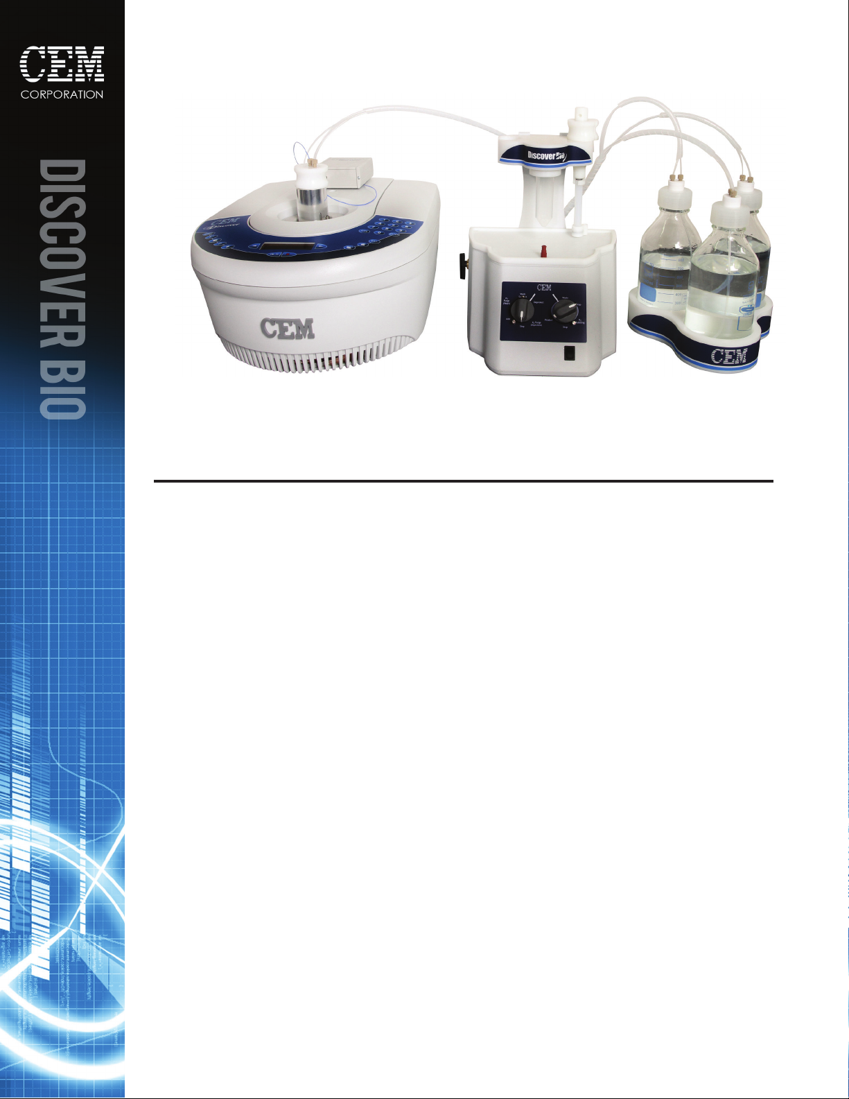
Introduction to the Discover Bio
The Discover Bio Manual Microwave Peptide Synthesizer is the newest manual microwave-enhanced peptide synthesis
system. Built on CEM’s exible Discover microwave platform, the Discover Bio allows the rapid and efcient synthesis
of peptides on scales from 0.05 to 0.5 mmol thanks to the efcient washing station and CEM’s patented circular
microwave cavity.
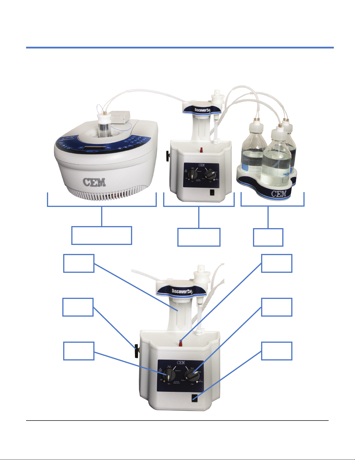
Discover Bio
Microwave Reactor
Product
Position
Nitrogen
Valve
Left
Knob
Discover Bio
Wash Station
Reagent
Bottles
Add Port
Right
Knob
Power
Switch
2
Discover Bio™ Manual Microwave Peptide Synthesizer
600423 • Revision 2 • August 2017
Page 3

System Requirements
Bench and/or Fume Hood Space
The Discover Bio should be positioned on the bench such that access to the electrical outlets for the system is not
restricted. The Discover Bio requires the following space for system components:
Discover Bio Microwave Reactor
15” (w) x 20” (d) x 9” (h) [38 cm (w) x 51 cm (d) x 23 cm (h)]
(Depth includes 3” (8 cm) clearance behind instrument for unimpeded airow at rear fan ducts)
Discover Bio Wash Station
11” (w) x 11” (d) x 13” (h) [28 cm (w) x 28 cm (d) x 33 cm (h)]
Bottle Holder with Bottles
9.5” (w) x 9” (d) x 11” (h) [24 cm (w) x 22 cm (d) x 28 cm (h)]
Environmental Conditions
The Discover Bio is designed for indoor used only.
Temperature Range: 50 °F – 85 °F (10 °C – 29 °C)
Relative Humidity Range: 0 – 85%
Inert Gas Source
The Discover Bio requires an inert gas source (either high purity grade nitrogen or argon) capable of supplying 20
psi (20 L/min ow) within ten feet (10’)/three meters (3 m) of the rear of the instrument.
Electrical Requirements
The Discover Bio requires electrical power of 120 VAC (60 Hz, 1.7 A) (or 240 VAC [50 Hz, 1.7 A] where applicable).
Specic power requirements (120 VAC vs. 240 VAC) can be found on the nameplate afxed to the rear of the
Discover Bio Microwave Reactor and on the rear of the Discover Bio Wash Station.
Safety Information
Fume Ventilation
The Discover Bio operates as a semi-closed system, with minimal venting of any hazardous solvent fumes through
the vent line. The vent line must be vented into a proper chemical fume hood or exhaust line no longer than 10
feet (10’)/three meters (3 m) from the instrument.
In addition, adequate ventilation should be provided for preparation of reagents and solvents for use on the
system. All solvent bottles and the Waste Reservoir should be placed into proper secondary containers to minimize
the risk of exposure.
Waste Disposal
Waste produced by the Discover Bio can be hazardous. For detailed information on the safety requirements for the
chemicals used on the Discover Bio, refer to the appropriate SDS documents.
WARNING
Handle all waste under a fume hood, and wear suitable protective clothing. Dispose of all waste
in accordance with all applicable local, state, and federal heath and safety recommendations.
Discover Bio™ Manual Microwave Peptide Synthesizer
600423 • Revision 2 • August 2017
3
Page 4
Hardware Assembly and Setup
Wash Station Setup
When setting up the wash station, all tubing connections will be made on the rear of the unit. There are
eleven ports on the manifold, as well as two stainless steel ports. The proper connections for the manifold are
summarized in the table below.
Bottle Setup
Position
Number
1 Main Wash Nitrogen
2 Deprotection Nitrogen
3 Waste Vacuum
4 Main Wash Liquid
5 Deprotection Liquid
6 Waste Liquid
7 Reaction Vessel Sprayhead
8 Reaction Vessel Drain
9 Reaction Vessel Vent
10 Product Position Vacuum
11 Product Position Liquid
SS-1 Nitrogen Source
SS-2 System Vent
Tubing Connection
1. Place the three 1 L glass bottles in the bottle holder.
2. Set up the Wash Solvent bottle.
2.1. Connect a bottle cap to the 1 L bottle to be used for wash solvent. Ensure the dip tube
reaches the bottom of the bottle and that the dip tube lter is in place.
2.2. Connect the bottle tubing to the cap. The tube labeled “LIQ” should be connected to the
same port as the dip tube. The unlabeled tube should be connected to the port without a dip
tube.
2.3. Connect the other end of the bottle tubing to the rear of the Wash Station. The tube labeled
“LIQ” should be connected to position 4. The unlabeled tube should be connected to
position 1.
3. Set up the Deprotection bottle.
3.1. Connect a bottle cap to the 1 L bottle to be used for deprotection solution. Ensure the dip
tube reaches the bottom of the bottle and that the dip tube lter is in place.
3.2. Connect the bottle tubing to the cap. The tube labeled “LIQ” should be connected to the
same port as the dip tube. The unlabeled tube should be connected to the port without a dip
tube.
3.3. Connect the other end of the bottle tubing to the rear of the Wash Station. The tube labeled
“LIQ” should be connected to position 5. The unlabeled tube should be connected to position
2.
4
Discover Bio™ Manual Microwave Peptide Synthesizer
600423 • Revision 2 • August 2017
Page 5
4. Set up the Waste bottle.
4.1. Connect a bottle cap to the 1 L bottle to be used for waste. Cut the dip tube to
approximately 1.5” (~4 cm) in length.
4.2. Connect the bottle tubing to the cap. The tube labeled “LIQ” should be connected to the
same port as the dip tube. The unlabeled tube should be connected to the port without a dip
tube.
4.3. Connect the other end of the bottle tubing to the rear of the Wash Station. The tube labeled
“LIQ” should be connected to position 6. The unlabeled tube should be connected to position
3.
Nitrogen and Vent Line Setup
1. Connect the nitrogen source to stainless steel port 1. Set the incoming pressure to approximately
20 psi.
2. Cut a piece of tubing (no greater than 10’ (~3 m) in length) and connect it to stainless steel port 2
using a stainless nut. This will serve as the vent line for the entire system. This tubing should be
run into a ventilated fume hood.
Product Collection Position Setup
1. Cut two pieces of tubing approximately 18” (45 cm).
2. Take one piece of tubing and, using yellow ferrules and nuts, connect one end to the left port on
the rear of the Product Collection Position, then connect the other end to position 10.
3. Take one piece of tubing and, using yellow ferrules and nuts, connect one end to the right port on
the rear of the Product Collection Position, then connect the other end to position 11.
Standard (25 mL) Vessel Setup
1. Open the reaction vessel by pressing the vessel body up into the vessel top and rotating.
2. Connect the sprayhead line.
2.1. Unscrew the sprayhead. Cut a length of tubing (~48” (120 cm)). Thread one end through the
center port on the reaction vessel top.
2.2. Put a yellow ferrule onto the end of the tubing so that the smaller end is near the end of the
tube, then press the end of the tubing into the sprayhead. Screw the sprayhead back into
the sprayhead port to secure the line.
2.3. Using a yellow ferrule and nut, connect the other end of the tubing to position 7 on the rear
of the Wash Station.
Discover Bio™ Manual Microwave Peptide Synthesizer
600423 • Revision 2 • August 2017
5
Page 6
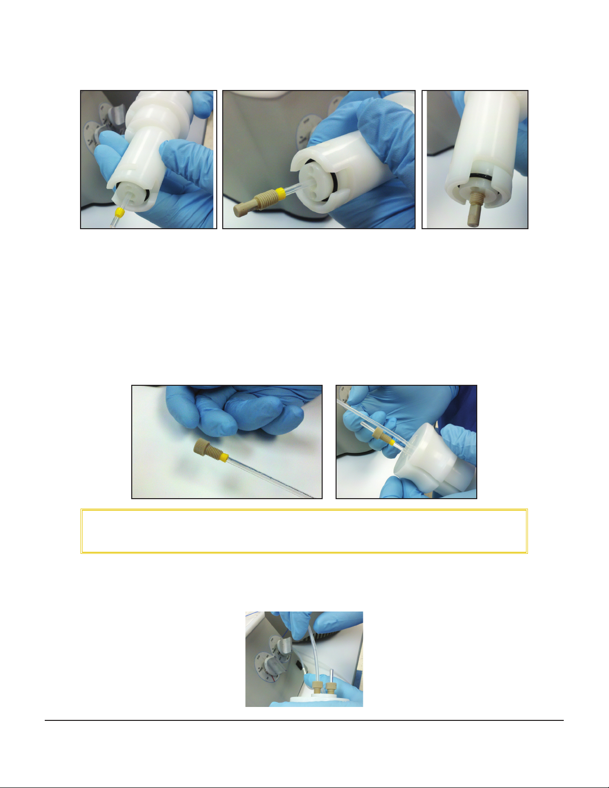
2.4. Reconnect the reaction vessel body to the top by pressing the body up into the top and
rotating.
3. Connect the thermowell.
3.1. Place a yellow ferrule and nut on the end of the thermowell.
3.2. Insert the thermowell into one of the side ports of the reaction vessel top so that the bottom
of the thermowell is just resting on the bottom of the vessel. Secure the thermowell with
the nut.
4. Connect the reaction vessel vent line.
4.1. Cut a length of tubing (~48” (120 cm)). Using a yellow ferrule and nut, connect the tubing to
the other side port of the reaction vessel top, being careful to bend the sprayhead line out of
the way.
CAUTION
Do not overtighten the tting on the thermowell, as this can break the thermowell and damage
the ber-optic probe.
4.2. Using a yellow ferrule and nut, connect the other end of the tubing to position 9 on the rear
of the Wash Station
5. Connect the RV Drain line.
6
Discover Bio™ Manual Microwave Peptide Synthesizer
600423 • Revision 2 • August 2017
Page 7

5.1. Cut a length of tubing (~60” (150 cm)). Using yellow ferrules and nuts, connect one end of
the tubing to the port on the bottom of the vessel.
5.2. Connect the other end to position 8 on the rear of the Wash Station.
Discover Setup
Temperature Probe Assembly
1. Connect one end of the serial cable to the rear of the FISO temperature control box. Connect the
other end of the serial cable to the COM2 port on the rear of the Discover.
2. Connect the blue ber-optic temperature probe to the FISO control box, taking care not to bend
the probe.
Calibration of the Fiber-Optic Probe
1. Connect the power cord to the rear of the Discover. Plug the power cord into an appropriate power
source. Locate the power switch on the left side of the Discover and turn the power on.
2. After the Discover has started up, press the EDIT key to open the System Menus.
3. The rst menu option will be Temperature. Press ENTER to open the Temperature Menu.
4. Use the right arrow key to scroll to “Select Alternate” and press ENTER.
5. Use the right arrow key to change to “DEVICE = FIBER-OPTIC” and press ENTER.
6. The Discover will return to the Home screen. Press EDIT to open the System Menus, then press
ENTER to open the Temperature Menu again.
7. Use the right arrow key to scroll to “Enter Calibration” and press ENTER.
8. Press EDIT, then use the numeric keypad on the right of the Discover to enter the seven digit GF
number printed on the white band at the base of the blue ber-optic probe.
9. Ensure the GF number is correctly entered, and press ENTER to save the calibration value in the
software.
10. Press HOME to return to the Home screen.
Discover Bio™ Manual Microwave Peptide Synthesizer
600423 • Revision 2 • August 2017
7
Page 8

Setting Discover for Open Vessel Mode
1. From the Home screen, press EDIT to open the System Menus.
2. Use the arrow keys ( and ) to scroll to Open Vessel and press ENTER.
3. Use the right arrow key to set “RUN OPEN VESSEL: YES” and press ENTER.
4. The Discover will return to the Home screen. Ensure that the top line of the screen says “OPEN
VESSEL”.
5. Insert the Open Vessel Attenuator so that the two tabs line up with the two slots, and lock into
place.
General Instrument Operation
Programming a New Method
1. Press the OPEN key.
2. Use the left arrow key to select “New Method” and press ENTER.
3. The rst parameter will be Mode. Use the right arrow key to select SPS mode and press
ENTER.
4. Using the numeric keypad, enter the microwave power setting (in W) and press ENTER.
5. Using the numeric keypad, enter the maximum temperature setting (in °C) and press ENTER.
6. Using the numeric keypad, enter the run time (in min:sec) and press ENTER.
7. Using the numeric keypad, set the Delta Temperature value to 5 °C and press ENTER.
8. Using the right arrow key set stirring to “OFF” and press ENTER.
9. Using the right arrow key set cooling to “OFF” and press ENTER.
10. Using the right arrow key set “NEXT STAGE = (N)” and press ENTER.
11. Using the right arrow key set “SAVE METHOD = (Y)” and press ENTER.
12. Using the arrow keys ( and ) to scroll to the desired characters and ENTER to select, enter a
name for the method. When the name has been entered, use the arrow keys ( and ) to
highlight “Exit” and press ENTER. The method is now saved in the rmware.
Loading an Existing Method
1. Press the OPEN key.
2. Use the arrow keys ( and ) to scroll to the desired method name, then press ENTER to load the
method.
3. The method name should be displayed on the Home screen, along with the programmed
parameters.
8
Discover Bio™ Manual Microwave Peptide Synthesizer
600423 • Revision 2 • August 2017
Page 9

Recommended Synthesis Parameters
Recommended Microwave Methods
Method Power Max Temp. Run Time Delta Temp.
Deprotection 20 W 75 °C 3:00 5 °C
Coupling 20 W 75 °C 5:00 5 °C
TFA Cleavage 15 W 38°C 30:00 5 °C
NOTE
Cysteine and histidine couplings should be performed at 50 °C to reduce racemization. Cleavage
temperatures should never exceed 43 °C. All values for Power are suggested, and should be
adjusted depending on reaction scale. The goal is to reach the maximum temperature in 75
seconds for Deprotection and Coupling, and in 120 seconds for Cleavage.
WARNING
The Discover Bio reaction vessels should not be operated above 75 ºC.
Recommended Reagents for 0.1 mmol Scale
Activator Base Solution
Prepare a solution of ~0.3 M DIEA in DMF.
Number of
Couplings
5 19 1 20
10 38 2 40
Per Coupling: 4 mL
0.1 mmol Scale
mL
DMF
mL
DIEA
Final
Vol.
Deprotection Solution
Prepare a solution of 20% piperidine in DMF with 0.1 M HOBt monohydrate.
0.1 mmol Scale
Final Volume
50 40 10 0.77
100 80 20 1.5
500 400 100 7.7
Per Coupling: 7 mL
mL
DMF
mL
Pip.
g HOBt
monohydrate
NOTE
HOBt is optional, but is recommended for sequences susceptible to aspartimide formation.
Discover Bio™ Manual Microwave Peptide Synthesizer
600423 • Revision 2 • August 2017
9
Page 10

Amino Acids and Activator
g HBTU
Before beginning a synthesis, weigh out the required amino acid and activator for each coupling into a separate
vial.
0.1 mmol
Amino Acid MW
Fmoc-Ala-OH 311.3 0.156 0.190
Fmoc-Arg(Pbf)-OH 648.8 0.324 0.190
Fmoc-Asn(Trt)-OH 354.4 0.298 0.190
Fmoc-Asp(OtBu)-OH 411.5 0.206 0.190
Fmoc-Cyc(Trt)-OH 585.7 0.293 0.190
Fmoc-Gln(Trt)-OH 610.7 0.305 0.190
Fmoc-Glu(OtBu)-OH 425.5 0.213 0.190
Fmoc-Gly-OH 297.3 0.149 0.190
Fmoc-His(Trt)-OH 619.7 0.310 0.190
Fmoc-Ile-OH 353.4 0.177 0.190
Fmoc-Leu-OH 353.4 0.177 0.190
Fmoc-Lys(Boc)-OH 468.5 0.234 0.190
Fmoc-Met-OH 371.5 0.186 0.190
Fmoc-Phe-OH 387.4 0.194 0.190
Fmoc-Pro-OH 337.4 0.169 0.190
Fmoc-Ser(tBu)-OH 383.4 0.192 0.190
Fmoc-Thr(tBu)-OH 397.5 0.199 0.190
Fmoc-Trp(Boc)-OH 526.6 0.263 0.190
Fmoc-Tyr(tBu)-OH 459.6 0.230 0.190
Fmoc-Val-OH 339.4 0.170 0.190
Scale
g AA
10
Discover Bio™ Manual Microwave Peptide Synthesizer
600423 • Revision 2 • August 2017
Page 11

General Discover Bio Methods
Swelling the Resin
1. Set both knobs to “Stop”.
NOTE
It does not matter which “Stop” position is used on the right knob.
2. Turn on the nitrogen source, then turn on the nitrogen to the system by setting the nitrogen control
knob to pressure (the knob should be pointing down) and the vacuum pump.
3. Slide the drain line out of the groove in the top of the vessel assembly. Open the reaction vessel by
pressing the vessel body up and rotating.
Add the resin to the vessel. Seal the vessel by pressing the vessel body up into the vessel top and
rotating. Slide the drain line back into the groove in the top of the vessel assembly. Place the
vessel in the reaction vessel holder.
4. Set the left knob to “Wash Solvent” to begin adding solvent to the reaction vessel.
Discover Bio™ Manual Microwave Peptide Synthesizer
600423 • Revision 2 • August 2017
11
Page 12

5. When the desired volume of solvent has been added to the vessel, set the left knob to “N2 Purge
(Wash)” to purge any solvent remaining in the lines. When all solvent has been purged into the
vessel, set the left knob to “Stop”.
NOTE
Purging the line will add an additional 1-2 mL of solvent to the reaction vessel.
6. Allow the resin to swell for approximately 15 minutes. Optionally, the resin can be bubbled during
swelling by setting the right knob to “N2 Bubbling” after the solvent has been added.
7. After the resin has swollen, drain the solvent from the reaction vessel by setting the left knob to
“N2 Purge (Wash)” the right knob to “Waste”. Once all the solvent has drained from the vessel, set
the right knob to “Stop”.
Performing a Deprotection
1. Set the left knob to “Deprotect” to begin adding deprotection solution to the reaction vessel.
2. When the desired volume of deprotection solution has been added to the vessel, set the left knob
to “N2 Purge (Deprotect)” to purge any remaining deprotection solution in the lines. When all
reagent has been purged into the vessel, set the left knob to “Stop”.
NOTE
Purging the line will add an additional 1-2 mL of deprotection solution to the reaction vessel.
3. Set the right knob to “N2 Bubbling”.
4. Ensure the ber-optic probe is fully inserted into the thermowell.
5. Insert the reaction vessel into the Discover cavity. Load the Deprotection microwave method, and
press the Play/Pause key to begin the method.
WARNING
The Discover Bio reaction vessels should not be operated above 75 ºC.
6. When the microwave method is nished, remove the reaction vessel from the Discover cavity and
place it in the vessel holder. Set the left knob to “N2 Purge (Wash)” the right knob to “Waste”.
7. When all the solvent has drained, set the right knob to “Stop”. Set the left knob to “Wash Solvent”
and add approximately 7 mL of solvent to the vessel, then set the left knob to “Stop”. Optionally,
to bubble the resin for a more efcient wash, turn the right knob to “N2 Bubbling” and allow the
resin to bubble for ve seconds.
8. Set the left knob to “N2 Purge (Wash)”, then set the right knob to “Waste” to drain the reaction
vessel. Set both knobs to “Stop”.
9. Repeat steps 7 and 8 two more times.
Performing a Coupling
1. Set the left knob to “Add” and the right knob to “Stop”.
2. Dissolve the appropriate amino acid, activator, and activator base in a total volume of
approximately 4 mL.
12
Discover Bio™ Manual Microwave Peptide Synthesizer
600423 • Revision 2 • August 2017
Page 13

3. Draw the coupling solution into a 10 mL syringe. Insert the luer tip of the syringe into the injection
port. Inject the coupling solution through the injection port into the reaction vessel.
4. To purge the injection port line, draw air into the syringe, then inject the air through the injection
port to fully purge the coupling solution into the reaction vessel.
NOTE
Purging the line will add an additional 1-2 mL of coupling solution to the reaction vessel.
5. Repeat step 4.
6. Set the left knob to “Stop”. Set the right knob to “N2 Bubbling”.
7. Ensure the ber-optic probe is fully inserted into the thermowell.
8. Insert the reaction vessel into the Discover cavity. Load the Coupling microwave method, and press
the Play/Pause key to begin the method.
WARNING
The Discover Bio reaction vessels should not be operated above 75 ºC.
9. When the microwave method is nished, remove the reaction vessel from the Discover cavity and
place it in the vessel holder. Set the right knob to “Waste” to drain the reaction vessel.
10. When all the solvent has drained, set the right knob to “Stop”. Set the left knob to “Wash Solvent”
and add approximately 7 mL of solvent to the vessel, then set the left knob to “Stop”. Optionally,
to bubble the resin for a more efcient wash, turn the right knob to “N2 Bubbling” and allow the
resin to bubble for ve seconds.
11. Set the left knob to “N2 Purge (Wash)”, then set the right knob to “Waste” to drain the reaction
vessel. Set both knobs to “Stop”.
12. Repeat steps 10 and 11 two more times.
Performing a Cleavage
1. Set both knobs to “Stop.” Turn off the nitrogen source.
2. Remove the solvent bottle, then connect a solvent bottle of DCM.
3. Turn on the nitrogen source.
4. Set the left knob to “Wash Solvent” and add approximately 7 mL of solvent to the vessel, then set
the left knob to “Stop”. Optionally, to bubble the resin for a more efcient wash, turn the right
knob to “N2 Bubbling” and allow the resin to bubble for ve seconds.
5. Set the left knob to “N2 Purge (Wash)”, then set the right knob to “Waste” to drain the reaction
vessel. Set both knobs to “Stop”.
6. Repeat steps 4 and 5 two more times.
Discover Bio™ Manual Microwave Peptide Synthesizer
600423 • Revision 2 • August 2017
13
Page 14

7. Slide the drain line out of the groove in the top of the vessel assembly. Open the reaction vessel by
pressing the vessel body up and rotating it counterclockwise.
8. Add the cleavage cocktail to the vessel. Seal the vessel by pressing the vessel body up into the
vessel top and rotating. Slide the drain line back into the groove in the top of the vessel assembly.
Place the vessel in the Discover.
9. Load the Cleavage microwave method, and press the Play/Pause key to begin the method.
10. When the microwave is nished, remove the reaction vessel from the Discover cavity and place it in
the vessel holder.
11. Connect a clean, labeled centrifuge tube to the product manifold.
12. Turn the right knob to “Product” to drain the cleaved peptide into the centrifuge tube.
13. Remove the centrifuge tube containing the cleaved peptide. The peptide is now ready to be
precipitated and analyzed.
14. Set the right knob to “Stop”. Set the left knob to “Wash Solvent” and add approximately 7 mL of
DCM to the vessel. Set the left know to “N2 Purge (Wash)”, then set the right knob to “Waste” to
drain the reaction vessel. Set both knobs to “Stop”.
15. Repeat step 12 two more times.
16. Open the reaction vessel and remove the spent resin for disposal.
17. Repeat step 12.
18. Set both knobs to “Stop.” Turn off the nitrogen source.
19. Remove the solvent bottle, then connect a solvent bottle of wash solvent.
20. Turn on the nitrogen source.
14
Discover Bio™ Manual Microwave Peptide Synthesizer
600423 • Revision 2 • August 2017
Page 15

Using the 4 mL Vessel for Smaller Scale
The 4 mL reaction vessel is used for small scale synthesis (below 0.1 mmol scale). The 4 mL vessel does not have
a sprayhead. All additions and washes must be added manually by opening the top of the reaction vessel.
Connecting the 4 mL Vessel
1. Place a yellow ferrule and nut on the end of the thermowell. Insert the thermowell into the center
port of the reaction vessel top so that the bottom of the thermowell is on the bottom of the vessel.
Secure the thermowell with the nut.
2. Connect the RV Vent line to the side port of the reaction vessel top.
3. Connect the RV Drain line to the port on the bottom of the vessel.
Discover Bio™ Manual Microwave Peptide Synthesizer
600423 • Revision 2 • August 2017
15
Page 16

Maintenance Procedures
After Each Use
• Clean the thermowell by wiping with a dry, lint-free cloth.
• If cleavagae was performed, clean the Product lines.
• Connect a 50 mL centrifuge tube to the product position.
• Open the reaction vessel and add ~20 mL dichloromethane to the reaction vessel. Close the
reaction vessel.
• With the pump turned on, turn the right knob to “Product” to drain the dichloromethane into
the centrifuge tube.
• Repeat with an additional 20 mL dichloromethane.
Monthly Maintenance
• Replace the dip tube lters in the main solvent and deprotection bottles.
Semiannual Maintenance
• Replace the Wash Solvent with methanol and perform a wash of the reaction vessel.
• Replace the frit on the bottom of the reaction vessel.
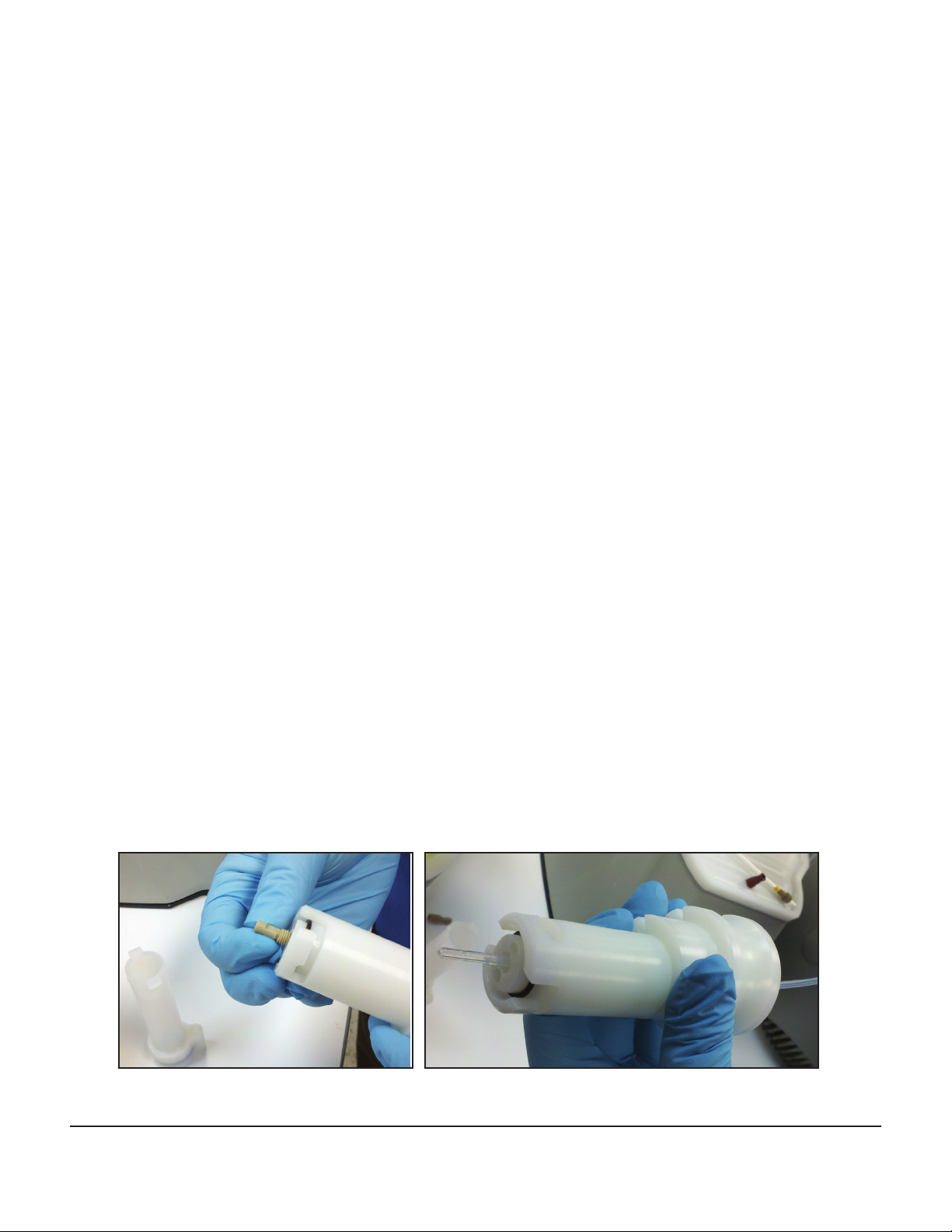
Replacement of Reaction Vessel Frit
1. Remove the drain line from the bottom of the reaction vessel.
2. Open the reaction vessel by pressing up into the reaction vessel top and rotating.
16
Discover Bio™ Manual Microwave Peptide Synthesizer
600423 • Revision 2 • August 2017
Page 17

3. Unscrew the bottom of the reaction vessel.
4. Using the frit removal tool, pop the frit out of the vessel body.
5. Insert a new frit into the vessel body.
6. Screw the vessel body into the bottom of the reaction vessel. Close the reaction vessel by pressing
up into the reaction vessel top and turning counterclockwise. Connect the drain line to the bottom
of the reaction vessel.
Discover Bio™ Manual Microwave Peptide Synthesizer
600423 • Revision 2 • August 2017
17
Page 18

Spare Parts and Accessories
System
Product Part Number
Discover Bio System 925496
Includes the following:
Discover Bio Microwave Reactor (select one)
120 v (60 Hz) Power Supply 909450
240 v (50 Hz) Power Supply 909455
Power Cord (varies by country)
Discover Bio Wash Station (select one)
120 v (60 Hz) Power Supply 908400
240 v (50 Hz) Power Supply 908405
Power Cord (varies by country)
Fiber-Optic Temperature Control 541176
Discover Bio Accessory Kit 908410
Accessories and Consumables
Product Part Number
4 mL Reaction Vessel Assembly 543505
Replacement Frits for 4 mL Vessel (Qty 50) 215005
25 mL Reaction Vessel Assembly 543500
Replacement Frits for 25 mL Vessel (Qty 50) 215055
50 mL Polypropylene Centrifuge Tubes (Qty 25) 167150-M
1 L Glass Bottle 167550
Two-Port GL45 Bottle Cap with Dip Tube 167559
Tubing for Bottle Cap 216780-M
Dip Tube Filters (Qty 50) 167485-M
Bottle Holder 543510
Fiber-Optic Temperature Probe 314325
Replacement Thermowell 181110
18
Discover Bio™ Manual Microwave Peptide Synthesizer
600423 • Revision 2 • August 2017
Page 19

Limited Warranty
What Is Covered:
CEM Corporation warrants that the instrument will be free of any defect in parts or workmanship and will, at
its option, replace or repair any defective part (excluding consumables) or instrument.
For How Long:
This warranty remains in effect for 365 days from date of delivery to the original purchaser.
What Is Not Covered:
This warranty does not cover parts or workmanship damaged due to:
• Neglect, abuse or misuse, or theft
• Damage caused by or to test samples,
• Damage incurred during instrument relocation,
• Damage caused by or to any attached equipment,
• Use of incorrect line voltages or fuses,
• Fire, ood, “acts of God” or other contingencies beyond the control of CEM Corporation,
• Improper or unauthorized repair, or
• Any other damage caused by purchaser or its agents.
Responsibilities of Purchaser:
• To ensure warranty coverage, the purchaser must:
• Use the instrument according to directions,
• Connect the instrument properly to a power supply of proper voltage,
• Replace blown fuses,
• Replace consumables and
• Clean the instrument as required.
How to Get Service:
Purchaser should contact the Service Department of CEM Corporation or the nearest CEM subsidiary or dis-
tributor for return authorization and for proper crating and shipping instructions to return instrument, freight
prepaid, for service. On-site repairs by an authorized service technician are available through the CEM Service
Department. Travel costs will be charged to the purchaser for onsite repairs.
Within the U.S. Outside the U.S.
CEM Corporation CEM Corporation
3100 Smith Farm Rd. 3100 Smith Farm Rd.
Matthews, NC 28104-5044 Matthews, NC 28104-5044
(800) 726-5551 (704) 821-7015
Fax: (704) 821-4368 Fax: (704) 821-4368
Warranty Disclaimer:
CEM Corporation hereby excludes and disclaims any warranty of merchantability or tness for any particular
purpose. No warranty, express or implied, extends beyond the face hereof. CEM Corporation shall not be liable for loss of use of instrument or other incidental or consequential costs, expenses or damages incurred by
the purchaser or any other user. This warranty is not transferable.
Purchaser’s Rights under State Law:
This warranty gives the purchaser specic legal rights, and the purchaser may also have other rights that vary
from state to state.
Discover Bio™ Manual Microwave Peptide Synthesizer
600423 • Revision 2 • August 2017
19
Page 20

CEM Corporation
PO Box 200
Matthews, NC 28106
Tel: 800-726-3331
Tel: 704-821-7015
Fax: 704-821-7894
Email: info@cem.com
www.cem.com
France
CEM μWave S.A.S.
Immeuble Ariane
Domaine Technologique de Saclay
4, rue Rene’ Razel
91892 ORSAY Cedex
Tel: 33 (01) 69 35 57 80
Fax: 33 (01) 60 19 64 91
Email: info.fr@cem.com
www.cemfrance.fr
Germany, Austria, Swit-
zerland
CEM GmbH
Carl-Friedrich-Gauss-Str.9
47475 Kamp-Lintfort
Tel: (49) 2842-9644-0
Fax: (49) 2842-9644-11
Email: info@cem.de
www.cem.de
CEM has been an ISO-certied
facility since 1994.
Ireland
CEM Technology (Ireland) Ltd.
Sky Business Centre
9a Plato Business Park
Damastown
Dublin 15
Tel: +353 (0) 1 885 1752
Fax: +353 (0) 1 885 1601
Email: info.ireland@cem.com
www.cemmicrowave.co.uk
Italy
CEM S.R.L.
Via Dell’ Artigianato, 6/8
24055 Cologno al Serio (Bg)
Tel: (39) 35-896224
Fax: (39) 35-891661
Email: info.srl@cem.com
www.cemmicroonde.com
Japan
CEM Japan K.K.
2-18-10 Takanawa
Minato-ku, Tokyo
108-0074
Tel: +81-3-5793-8542
Fax: +81-3-5793-8543
Email: info@cemjapan.jp
www.cemjapan.co.jp
Discover Bio™ Manual Microwave Peptide Synthesizer
600423 • Revision 1 • August 2017
United Kingdom
CEM Microwave Technology Ltd.
2 Middle Slade
Buckingham Industrial Estate
Buckingham MK181WA
Tel: (44) 1280-822873
Fax: (44) 1280-822342
Email: info.uk@cem.com
www.cemmicrowave.co.uk
 Loading...