

Page 1
User manual
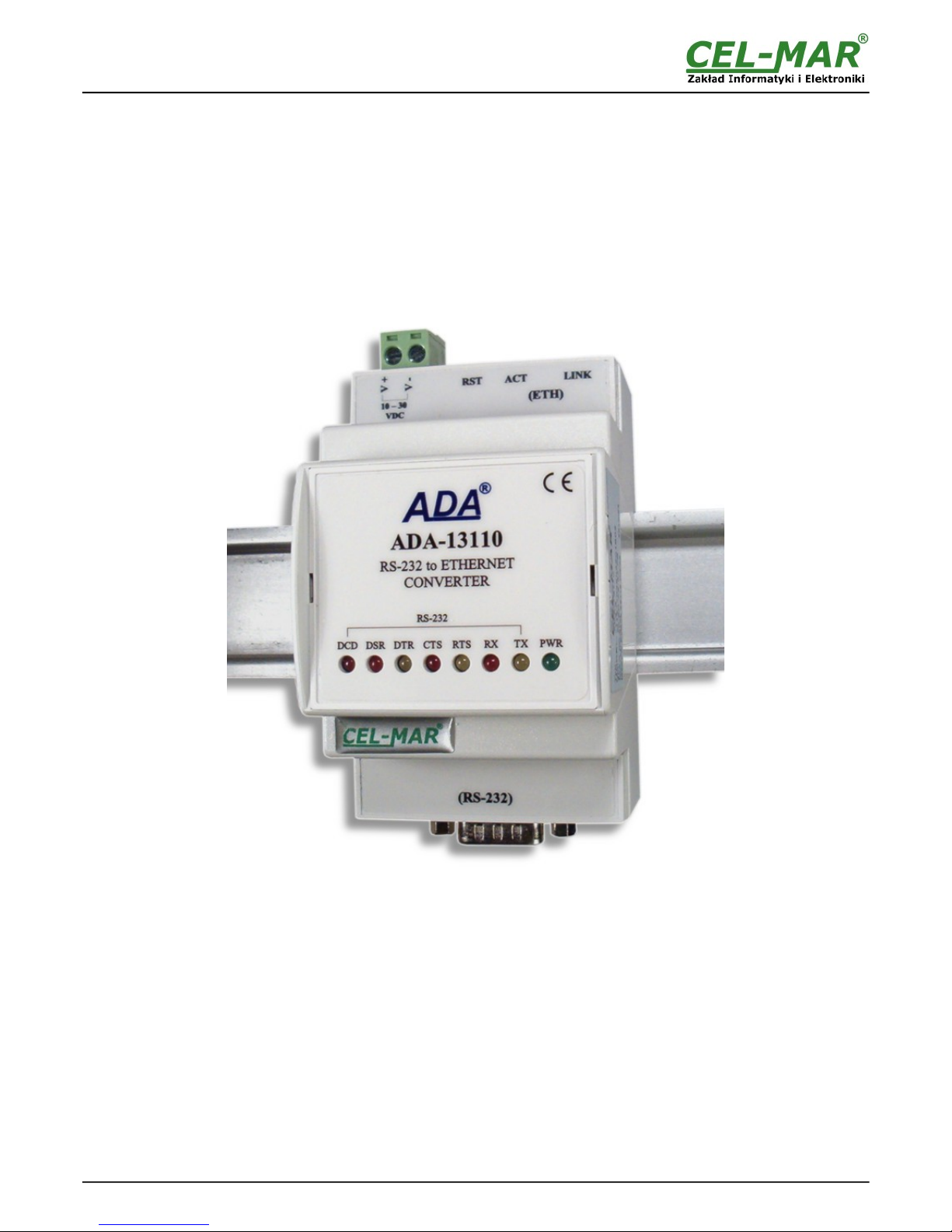
ADA-13110
RS232 to ETHERNET converter
1
io_ada-13110_v.1.12_en
ADA-13110
Copyright © 2001-2017 CEL-MAR sp.j.
Page 2

Contents
1. GENERAL INFORMATION...................................................................................................................................................................... 3
1.1. WARRANTED INFORMATION.......................................................................................................................................................3
1.2. GENERAL CONDITIONS FOR SAFE USE.................................................................................................................................... 3
1.3. CE LABEL....................................................................................................................................................................................... 3
1.4. ENVIRONMENTAL PRESERVATION............................................................................................................................................ 3
1.5. SERVICE AND MAINTENANCE..................................................................................................................................................... 3
1.6. PACK CONTENTS.......................................................................................................................................................................... 3
2. PRODUCT INFORMATION.....................................................................................................................................................................3
2.1. PROPERTIES................................................................................................................................................................................. 3
2.2. DESCRIPTION................................................................................................................................................................................ 4
2.3. ETHERNET NETWORK COMMUNICATION................................................................................................................................. 4
2.3.1. TCP/UDP SOCKET MODE COMMUNICATION....................................................................................................................4
2.3.2. COMMUNICATIONS IN THE VIRTUAL SERIAL PORT MODE (RealPort)...........................................................................4
2.3.3. COMMUNICATIONS IN THE SERIAL BRIDGE MODE.........................................................................................................4
2.3.4. OTHER COMMUNICATION TYPES......................................................................................................................................4
2.4. ISOLATION..................................................................................................................................................................................... 5
3. INSTALLATION....................................................................................................................................................................................... 5
3.1. ASSEMBLING.................................................................................................................................................................................5
3.2. ETHERNET NETWORK CONNECTION........................................................................................................................................ 5
3.2.1. CONNECTING TO NETWORK ADAPTER OF PC................................................................................................................6
3.2.2. CONNECTING FOR OPERATING IN REALPORT MODE....................................................................................................6
3.2.3. CONNECTION FOR OPERATING IN TCP & UDP SERIAL BRIDGE MODE........................................................................7
3.3. CONNECTION TO RS232 DEVICES............................................................................................................................................. 8
3.3.1. CONNECTING OF DEVICE WITH RS232 PORT, DTE TYPE (PC COMPUTER)................................................................ 8
3.3.2. CONNECTING OF DEVICE WITH RS232 PORT, DCE TYPE (MODEM, CODE READER)................................................ 9
3.4. POWER SUPPLY CONNECTION.................................................................................................................................................. 9
4. ACTIVATION........................................................................................................................................................................................... 9
5. CONFIGURATION................................................................................................................................................................................... 9
5.1. INITIAL CONFIGURATION USING ADAFINDER SOFTWARE................................................................................................... 10
5.1.1. ADAFINDER INSTALLATION.............................................................................................................................................. 10
5.1.2. NETWORK SETTING.......................................................................................................................................................... 10
5.2. CONFIGURATION AND MANAGEMENT BY THE USE OF INTERNET BROWSER..................................................................11
5.2.1. NETWORK CONFIGURATION............................................................................................................................................12
5.2.2. SERIAL PORT CONFIGURATION....................................................................................................................................... 12
5.2.2.1. SERIAL PORT PROFILE CONFIGURATION (OPERATING MODE).........................................................................12
5.2.2.1.1. REALPORT (VIRTUAL PORT) CONFIGURATION............................................................................................13
5.2.2.1.2. TCP SOCKETS CONFIGURATION.................................................................................................................... 13
5.2.2.1.2.1. TCP SERVER & CLIENT CONFIGURATION............................................................................................ 13
5.2.2.1.2.2. THE 'ENABLE TCP KEEP-ALIVE' OPTION CONFIGURATION................................................................14
5.2.2.1.2.3. SERIAL PORT TRANSMISSION PARAMETERS CONFIGURATION.......................................................15
5.2.2.1.3. UDP SOCKETS CONFIGURATION................................................................................................................... 15
5.2.2.1.3.1. UDP CLIENT & SERVER CONFIGURATION IN CASE OF MASTER DEVICE........................................15
5.2.2.1.3.2. UDP CLIENT & SERVER CONFIGURATION IN CASE OF SLAVE DEVICE...........................................16
5.2.2.1.3.3. SERIAL PORT TRANSMISSION PARAMETERS CONFIGURATION.......................................................17
5.2.2.1.4. SERIAL BRIDGE PROFILE CONFIGURATION.................................................................................................17
5.2.2.1.4.1. SERIAL PORT TRANSMISSION PARAMETERS CONFIGURATION.......................................................17
5.2.3. SYSTEM SETTINGS............................................................................................................................................................ 17
5.2.4. USERS CONFIGURATION..................................................................................................................................................17
5.2.4.1. CHANGING USER MANE AND PASSWORD............................................................................................................17
5.2.4.2. ADDING NEW USER W ITH LIMITED PERMISSIONS FOR CONFIGURATION OR MANAGEMENT......................18
5.2.5. MANAGEMENT.................................................................................................................................................................... 18
5.2.5.1. SERIAL PORTS MANAGEMENT................................................................................................................................18
5.2.5.2. CONNECTIONS MANAGEMENT................................................................................................................................18
5.2.6. ADMINISTRATION............................................................................................................................................................... 18
5.2.6.1. FILE MANAGEMENT................................................................................................................................................... 18
5.2.6.2. BACKUP & RESTORE CONFIGURATION................................................................................................................. 18
5.2.6.3. FIRMWARE UPDATE.................................................................................................................................................. 18
5.2.6.4. FACTORY DEFAULT SETTINGS...............................................................................................................................18
5.2.6.5. SYSTEM INFORMATION............................................................................................................................................18
5.2.6.6. REBOOT...................................................................................................................................................................... 19
5.2.6.7. LOGOUT – ENDING MANAGEMENT AND CONFIGURATION.................................................................................19
6. USING VIRTUAL PORT SERVICE [REALPORT]................................................................................................................................. 19
6.1. VIRTUAL PORT DRIVER INSTALLATION IN WINDOWS XP.....................................................................................................19
6.2. REALPORT CONFIGURATION IN WINDOWS XP...................................................................................................................... 19
7. FACTORY DEFAULT............................................................................................................................................................................ 21
8. TROUBLESHOOTING........................................................................................................................................................................... 21
9. VERSIONS............................................................................................................................................................................................ 21
10. SPECIFICATION................................................................................................................................................................................. 22
2
ADA-13110
Page 3
1. GENERAL INFORMATION
Thank you for your purchase of CEL-MAR Company product. This product has been completely tested and is covered by a two year
warranty on parts and operation from date of sale.
If any questions or problems arise during installation or use of this product, please do not hesitate to contact Technical Support at +48
41 362-12-46 or e-mail [email protected].
1.1. WARRANTED INFORMATION
ADA-13110 converter is covered by a two year warranty from date of sale. In case of being damaged it will be repair or the damaged
component will be replace. The warranty does not cover damage caused from improper use, materials consumption or any
unauthorized changes. If the product does not function (is damaged), or not operate in accordance with the instructions, will be
repaired or replaced.
All warranty and no warranty repairs must be returned with paid transport and insuring to the CEL-MAR Company.
CEL-MAR Company under no circumstances won't be responsible for ensuing damage from improper using the product or as a result
of random causes: the lightning discharge, the flood, the fire and the like.
CEL-MAR Company is not be held responsible for damages and loss including: loss of profits, loss of data, pecuniary losses ensuing
from using or the impossibility of using this product.
In specific cases CEL-MAR Company discontinue all warranties and in particular do not follow the user manual and do not accept
terms of warranty by the user.
1.2. GENERAL CONDITIONS FOR SAFE USE
The device should be installed in a safe and stable places (eg, electroinstallation cabinet), the powering cable should be arranged so
as not to be exposed to trampling, attaching, or pulling out of the circuit.
Do not put device on the wet surface.
Do not connect devices for nondescript powering sources,
Do not damage or crush powering wires.
Do not make connection with wet hands.
Do not adapt, open or make holes in casings of the device!
Do not immerse device in water or no other liquid.
Do not put the fire opened on device sources: candles, an oil lamps and the like.
Complete disable from the supply network is only after disconnecting the power supply circuit voltage.
Do not carry out the assembly or dis-assembly of the device if it is enabled. This may result to short circuit and damage the device.
The device can not be used for applications that determine human life and health (eg. Medical).
1.3. CE LABEL
The CE symbol on the device CEL-MAR means compatibility with electromagnetic compatibility Electromagnetic
Compatibility Directive EMC 2014/30/WE. Declaration of Conformity is available by contact with Technical Service
(email: [email protected]; phone: +48 41 362-12-46).
1.4. ENVIRONMENTAL PRESERVATION
This sign on the device inform about putting expended device with other waste materials. Device should send to the
recycling. (In accordance with the act about the Electronic Appliance Expended from day 29 of July 2005)
1.5. SERVICE AND MAINTENANCE
ADA-13110 converter does not require the servicing and maintenance.
Technical support is available at number +48 41 362-12-46 in 8.00-16.00, from Monday to Friday or e-mail [email protected].
1.6. PACK CONTENTS
The converter is delivered with: User Manual, ADANet software CD.
2. PRODUCT INFORMATION
2.1. PROPERTIES
● Functioning on ETHERNET network- IEEE 802.3 standard,
● 10/100BaseT physical layer,
● Connection Ethernet networks via RJ45 connector
● Baud rate 10/100Mbps (auto-sensing),
● Full or half duplex (auto-sensing) operates mode,
● Protocols: TCP, UDP, DHCP, SNMP, SSL/TLS, Telnet, Rlogin, LPD, HTTP/HTTPS, SMTP, ICMP, IGMP, ARP,
● WWW sever implemented for converter configuration,
● Configuration of net services according to user personal setting,
● Static or dynamic IP address (added by DHCP server),
● Diagnostics of serial and network port,
● Encoded transmission: DES (56-bit), 3DES (168-bit), AES (128/256-bit),
● Functioning in modes: virtual serial port, TCP serial bridge, UDP serial bridge, TCP sockets, UDP sockets,
● RS232 interface signals: Rx, Tx, RTS, CTS, DTR, DSR, DCD,
● RS232 baud rate ( bps): 50, 75, 110, 134, 150, 200, 300, 600, 1200, 1800, 2400, 4800, 9600, 14400, 19200, 28800, 38400,
57600, 115200, 230400,
● RS232 data format - Number of data bits: 5, 6, 7, 8; Parity checking: None, Odd, Even, Constantly 1, Constantly 0; Stop Bits: 1, 2,
● Transparent for all protocols, which the data format is compatible with the above specifications of RS232 interface e.g. MODBUS,
DNP, PROFIBUS and other,
3
ADA-13110
Page 4
● Connection RS-232 network via DSUB-9 Mail connector,
● External power supply 10 - 30 VDC stable min. 3W,
● 1000V= or 3000V= galvanic isolation between ETHERNET interface and power supply - depends on version,
● 1000V= or 3000V= galvanic isolation between RS232 interface and power supply - depends on version,
● Protection against power supply reverse connection,
● DIN 43880 standard - mounting in typical electro-installation unit,
● Rail mounting according to DIN35 / TS35 standard,
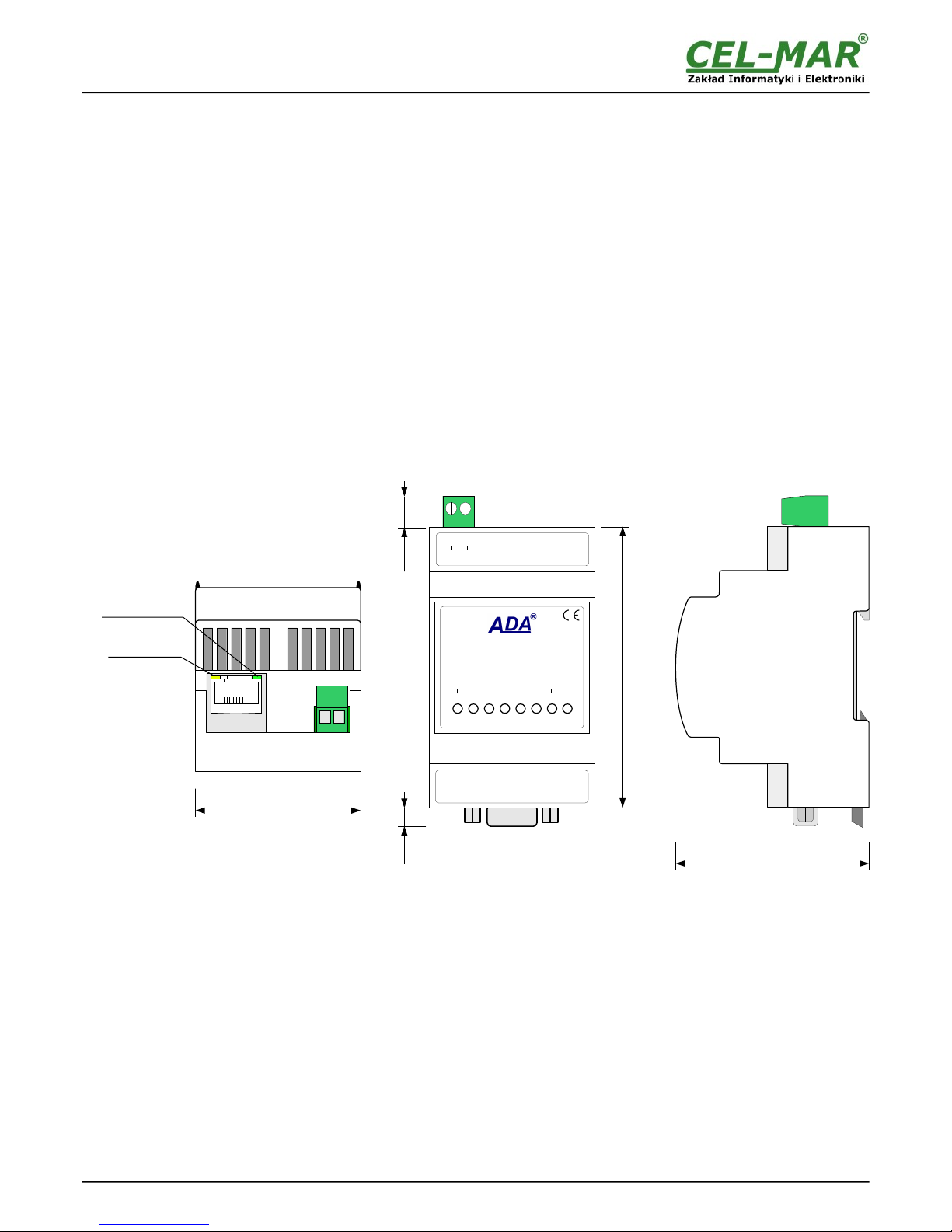
● Dimensions (W x D x H) 53mm x 62mm x 90mm.
2.2. DESCRIPTION
ADA-13110 converter is use for data transmission between devices equip with RS232 interface via LAN/WAN network. Data
transmission takes place without the interference of data format. Operating in ETHERNET network can be in Virtual Serial Port, TCP
serial bridge, UDP serial bridge, TCP sockets, UDP sockets. Converter can use protocols: TCP, UDP, DHCP, SNMP, SSL/TLS,
Telnet, Rlogin, LPD, HTTP/HTTPS, SMTP, ICMP, IGMP, ARP. Can be configured and managed via Internet browser – converter has
implemented W WW server. ADA-13110 has standard DB-9M (male) RS232 connector, screw terminal block for connecting the power
supply and RJ45 modular connector for ETHERNET network connection.
The converter transmits data via RS232 interface with maximum baud rate up to 230,4 kbps and uses signals Rx, Tx, RTS, CTS, DTR,
DSR, DCD of RS232 interface.
To the RS232 port of ADA-13110 can be connected to telephone exchanges, barcode scanners, modems, weight, magnetic card
readers. It is adapted for powering from the regular voltage external source which value should contain from 10V to 30V and was
provided from the power pack about 3W power. Converter has implemented protection against opposite polarization of power supply
and over-voltage protection ESD 15kV on RS232 interface lines.
We provide with converter the drivers which installed in the operating systems, will create an additional COM port. This port is the next
free number eg COM3, can be used like a standard COM port. However, it is not the real port existing in a computer, but only a virtual,
created by the system, therefore some programs running under DOS and links to this COM port may not function properly.
Fig 1. ADA-13110 view
2.3. ETHERNET NETWORK COMMUNICATION
2.3.1. TCP/UDP SOCKET MODE COMMUNICATION
Communication in the mode TCP/UDP sockets allows an application SCADA, MMI e.t.c., to transfer data to the serial port of the
converter via Ethernet network by the use of client and server TCP/UDP services.
2.3.2. COMMUNICATIONS IN THE VIRTUAL SERIAL PORT MODE (RealPort)
Communication in the virtual serial port mode allows an application SCADA, MMI e.t.c., to transfer data to the serial port of the
converter via Ethernet network, by the use virtual COM port , created in an operating system.
2.3.3. COMMUNICATIONS IN THE SERIAL BRIDGE MODE
Communication in the serial bridge mode allows transferring data via Ethernet network between serial port of the converter's ports in
one-to-one topology or one-to-many by the use of client and server TCP/UDP services.
2.3.4. OTHER COMMUNICATION TYPES
ADA-13010 converter can be configured in other communication types, like:
– terminal mode,
4
ADA-13110
(RS-232)
ADA-13110
RS-232 to ETHERNET
CONVERTER
PWRTXRX
RS-232
DCD DSR DTR CTS RTS
62mm
53mm
6mm 10mm
90mm
Network activity
transmitting / receiving
Connection activity
8
1
- +
ACT LINK
(ETH)
RST
V +
V -
10 – 30
VDC
Page 5
– modem emulation mode,
– console mode,
– user mode.
2.4. ISOLATION
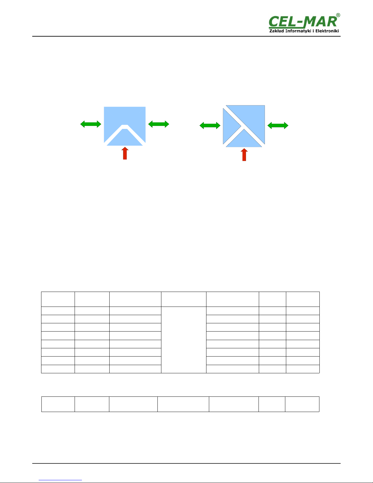
Converter ADA-13110 has galvanic isolation, on the level 1kV= or 3kV=, depend on version described in section VERSIONS.
Isolation from the power supply allows transmitting signals: Tx, Rx, RTS, CTS, DTR, DSR, DCD of RS232 interface.
3-way isolation allows transmitting signals: Tx, Rx, RTS of RS232 interface.
Fig. 2. Isolation structure
3. INSTALLATION
This chapter will show how to connect ADA-13110 to RS232 devices, LAN/WAN network and power supply and how to use it.
In the purpose of minimization of disruptions from environment is being recommended to:
● apply multipair type shielded cables, which shield can be connected to the earthing on one end of the cable,
● arrange signal cables in the distance not shorter than 25 cm from powering cables,
● apply cable of adequate cross-section due to voltage drops for converter powering,
● use Interference suppression filters for power supply converters that are installed within a single object.
● not supply converter from power circuit device that generates large impulse interference such as transmitters, contactors,
3.1. ASSEMBLING
The ADA-13110 converter case is adapted to assembly on TS-35 (DIN35) rail. To install the device on TS-35 should be the upper part
of the casing put hooks on the terminal and then press the bottom of the cover until you hear a characteristic "Click" sound.
3.2. ETHERNET NETWORK CONNECTION
The ADA-13110 has to be connected to ETHERNET network by the use of the switch, the HUB or directly to the PC network adapter.
The table below shows preparing of the straight cable for converter connection to switch or hub.
Table 1. The straight cable for connection to switch or hub.
RJ45 Pin
No.
Signal Wire Color
EIA/TIA 568B
Straight cable
UTP 4x2x0,5
Wire Color
EIA/TIA 568B
Signal RJ45 Pin
No.
1 TX+ White-Orange
2 TX- Orange
3 RX+ White-Green
4 Not used Blue
5 Not used White-Blue
6 RX- Green
7 Not used White-Brown
8 Not used Brown
White-Orange TX+ 1
Orange TX- 2
White-Green RX+ 3
Blue Not used 4
White-Blue Not used 5
Green RX- 6
White-Brown Not used 7
Brown Not used 8
The table below shows preparing of cross-over cable for the converter connection to PC network adapter or connections converters
together for functioning as point-to-point serial bridge.
Table 2. The cross-over cable for connection to PC network adapter or connections converters together for functioning as
point-to-point serial bridge.
RJ45 Pin
No.
Signal Wire Color
EIA/TIA 568B
Cross-Over Cable
UTP 4x2x0,5
Wire Color
EIA/TIA 568B
Signal RJ45 Pin
No.
5
ADA-13110
Power Supply
10 - 30VDC
ETHERNET
RS232
3-WAY ISOLATION
Power Supply
10 - 30VDC
ETHERNET RS232
POWER ISOLATION
Page 6
1 TX+ White-Orange
2 TX- Orange
3 RX+ White-Green
4 Not used Blue
5 Not used White-Blue
6 RX- Green
7 Not used White-Brown
8 Not used Brown
White-Green TX+ 1
Green TX- 2
White-Orange RX+ 3
Blue Not used 4
White-Blue Not used 5
Orange RX- 6
White-Brown Not used 7
Brown Not used 8
In the modular socket ETHERNET interface of converter, are implemented two LED's (Fig. 1):
– Green ACT signaling state of sending or receiving data,
– Orange LINK signaling active network connection.
ADA-13110 converter can function in the ETHERNET network as:
– virtual serial bridge [RealPort],
– TCP serial bridge,
– UDP serial bridge.
Additional information about Ethernet connection will be describe in chapters below.
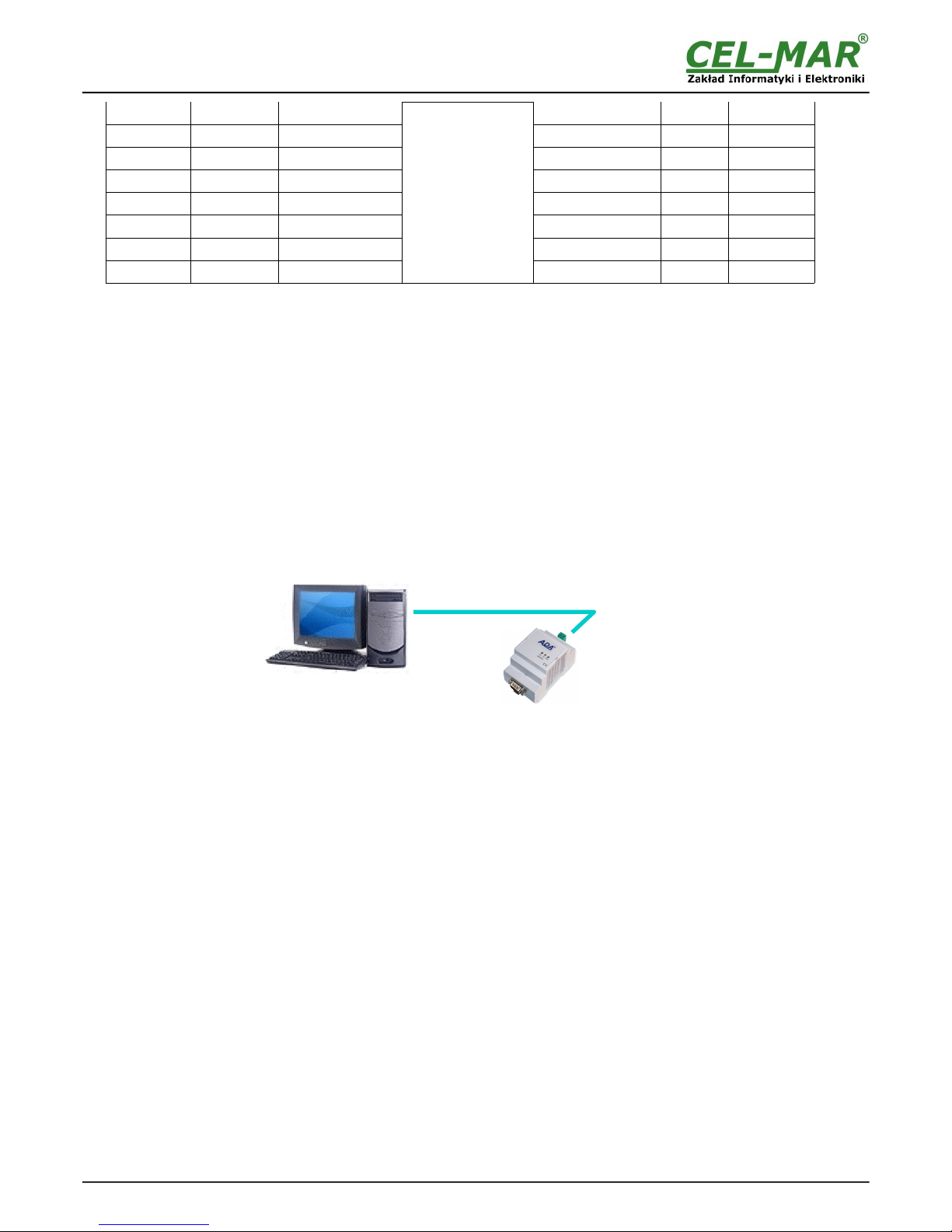
3.2.1. CONNECTING TO NETWORK ADAPTER OF PC
If there is not the switch or the HUB, it is possible to connect the ADA-13110 directly to a network adapter of PC using the cross-over
cable (Table 2). This connection can be used for converter configuration.
Fig 3. Direct connection to PC
3.2.2. CONNECTING FOR OPERATING IN REALPORT MODE
Figures 3 (above) and 4, 5 (below) show how correctly connect the ADA-13110 to LAN, WAN network or PC, for operating in virtual
serial port mode (RealPort).
For direct connection of the converter to PC network adapter, use the cross-over cable (see Table 2) and for connection by the use of
switch or HUB use the straight cable (see Table 1).
6
ADA-13110
PC with a network
adapter
Static IP address
ADA-13110
Static IP address
ETHERNET
Crossover cable
(Table 2)
Page 7
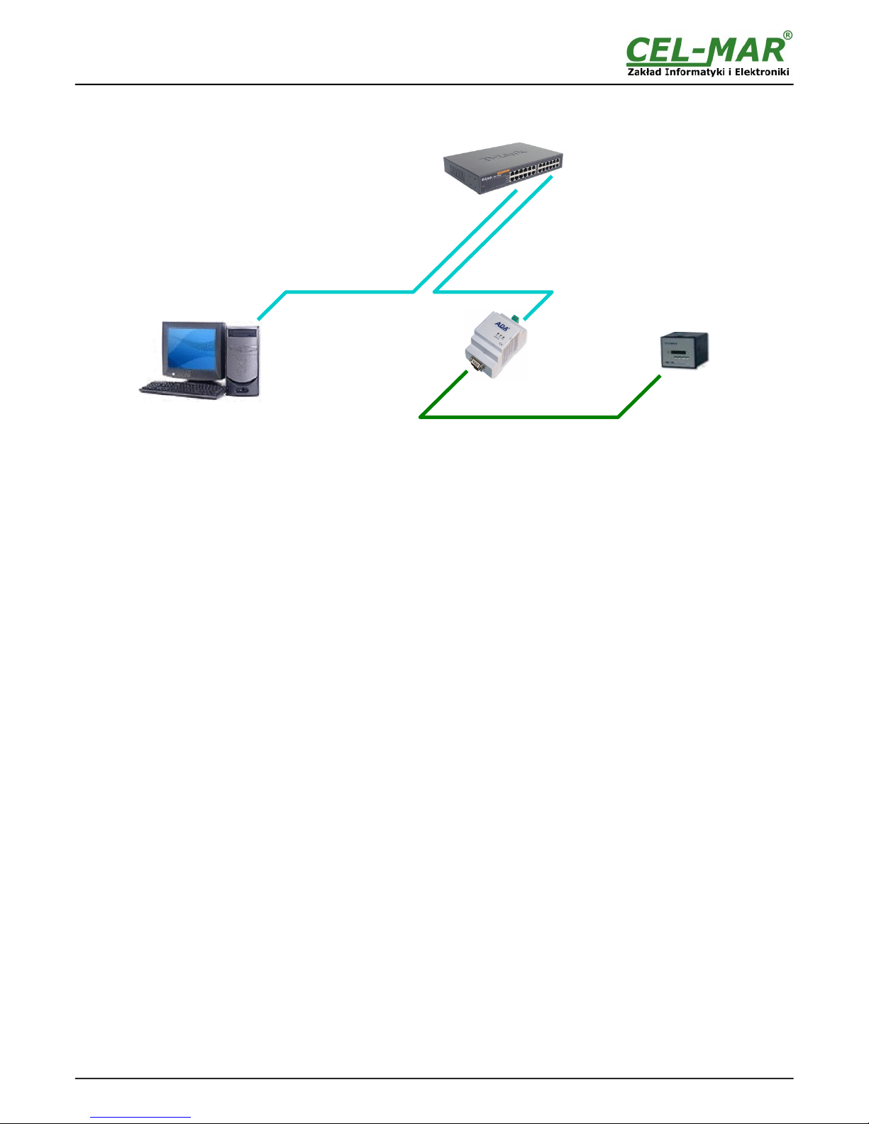
Fig 4. LAN connection via switch/hub to operating in the Real Port mode
7
ADA-13110
ETHERNET
Straight Cable
(Table 1)
Local network
ETHERNET
built on the switch
Device with
RS232 interface
RS232
PC with a network
adapter
Static IP address
ADA-13110
Static IP address
Page 8
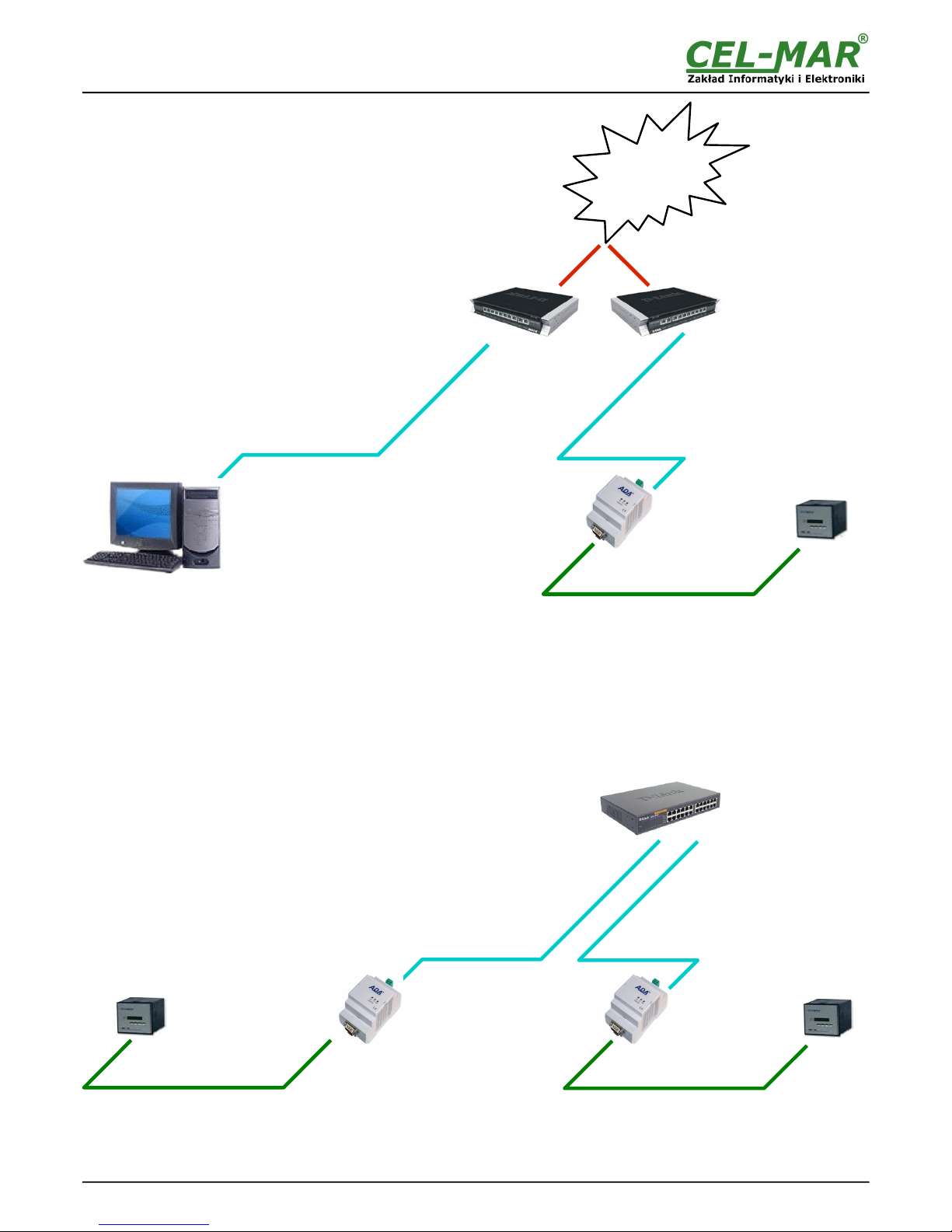
Fig 5. WAN connection to operating in the Real Port mode
3.2.3. CONNECTION FOR OPERATING IN TCP & UDP SERIAL BRIDGE MODE
Pictures below show how correctly connect the ADA-13110 to ETHERNET network for functioning in TCP & UDP serial bridge mode.
For connection by the use of network devices (router, switch or HUB) use the straight cable (see Table 1).
Fig 6. LAN connection to operating in the TCP/UDP serial bridge mode, one-to-one
8
ADA-13110
INTERNET
ROUTER
Public IP address
RS232
ROUTER
Public IP address
ETHERNET
Straight Cable
(Table 1)
Device with
RS232 interface
PC with a network
adapter
Static IP address
ADA-13110
Static IP address
ETHERNET
Straight Cable
(Table 1)
RS232
RS232
ETHERNET
Straight Cable
(Table 1)
Local network
ETHERNET
built on the switch
Device with
RS232 interface
ADA-13110
Static IP address
Device with
RS232 interface
ADA-13110
Static IP address
ETHERNET
Straight Cable
(Table 1)
Page 9
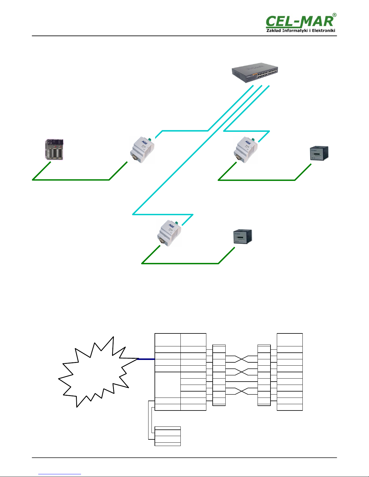
Fig 7. LAN connection to operating in the UDP serial bridge mode, one-to-many
3.3. CONNECTION TO RS232 DEVICES
3.3.1. CONNECTING OF DEVICE WITH RS232 PORT, DTE TYPE (PC COMPUTER)
ADA-13110 can be connected to RS232 port of PC computer by the use of RS232 extension cable CAB-DB9F/DB9F-C-1,8m
(available in our offer). Fig 8 below shows the example connecting to RS232 PC port.
Fig 8. ADA-13110 example connection to RS232 PC
9
ADA-13110
RS232
RS232
RS232
Local network
ETHERNET
built on the switch
SLAVE device
with
RS232 interface
ADA-13110
Static IP address
ETHERNET
Straight Cable
(Table 1)
ADA-13110
Static IP address
ADA-13110
Static IP address
ETHERNET
Straight Cable
(Table 1)
SLAVE device
with
RS232 interface
MASTER device
with
RS232 interface
Cable / Adapter
CAB-DB9F/DB9F-C-1,8m /
ADP-DB9F/DB9F-C
Tx+ (1)
Tx- (2)
Rx+ (3)
Rx- (6)
ADA-13110
V +
V -
V -
V +
1
2
3
4
6
5
9
7
8
Rx -2
Tx -3
DTR -4
DSR -6
RTS -7
RI -9 (NC)
GND -5
DCD -1
CTS -8
1
2
3
4
6
5
9
7
8
Rx -2
Tx -3
DTR -4
DSR -6
RTS -7
RI -9
GND -5
RS232 port
DTE/DB-9M
DCD -1
CTS -8
RJ45
ETHERNET
connector
Power supply
RS232
DTE/DB-9M
connector
DB-9F
socket
Device with
RS232 port
DTE type
LAN, WAN network
or PC
DB-9F
socket
Page 10
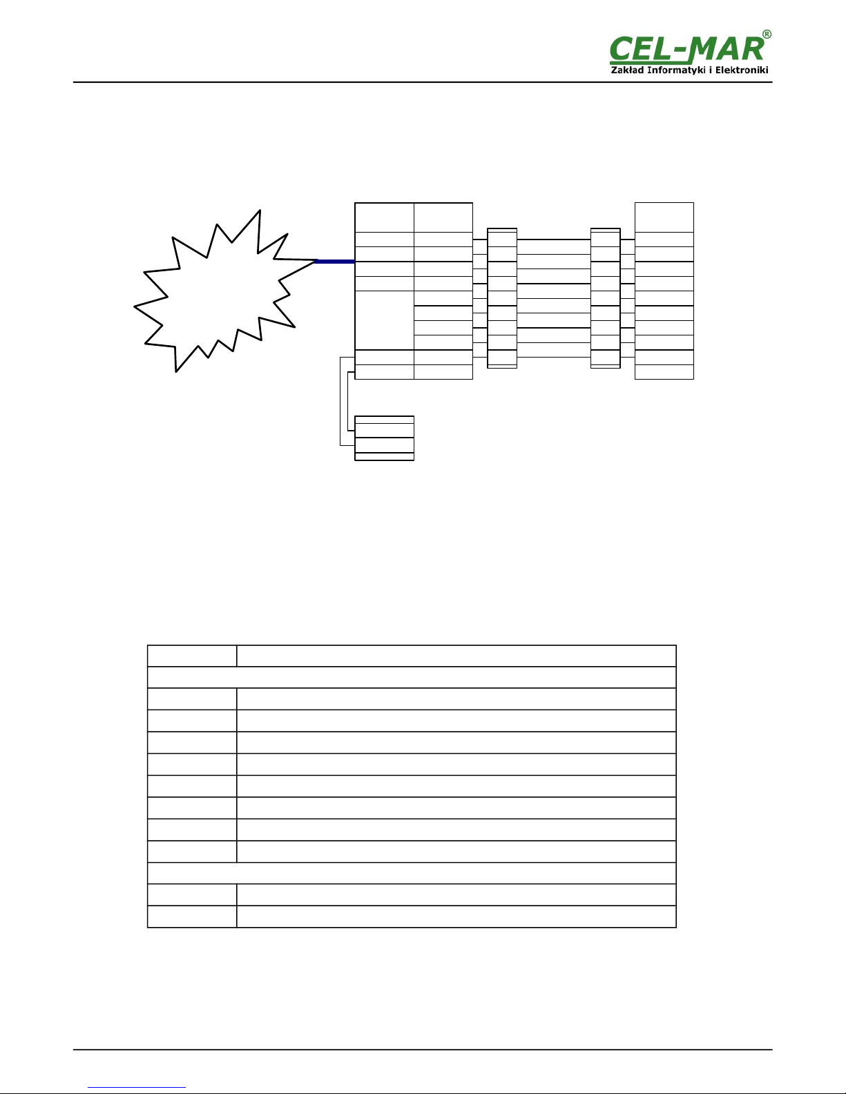
3.3.2. CONNECTING OF DEVICE WITH RS232 PORT, DCE TYPE (MODEM, CODE READER)
ADA-13110 can be connected to RS232 device DCE port type by the use of RS232 cable CAB-DB9F/DB9M-S-1,8m (available in our
offer). Fig 9 below shows the example connecting.
Fig 9. ADA-13110 example connection to RS232 device DCE port type
3.4. POWER SUPPLY CONNECTION
The power supply to the ADA-13110 converter should be DC (regulated) from 10 V= to 30V=. Nominal power is typically 3W, e.g. ZS12/250 or DR-15-24. Power cable from DC power supplies to device must not be longer than 3m.
Observe the polarity, connect positive (+) of DC power supplies to V+ and negative (-) end to V- terminal.
ADA-13110 has the protection from opposite connection power supply.
4. ACTIVATION
Converter can be powered after proper connection according to steps above. If the connection was made properly green LED PWR on
front panel of converter should lit, if not check polarization of power connection. During proper data transmission through converter
the LEDs Tx and Rx on the front panel and on RJ45 connector of Ethernet interface should blink. These LEDs are respectively:
LED Description
RS232 interface & Power
PWR
Signalization of power supply
RX
Signalization of data receiving by ADA-13110 converter from RS232.
TX
Signalization of data transmission from ADA-13110 converter through RS232.
RTS
ADA-13110 reports to device readiness data collection
CTS
Device confirms reception RTS signal from ADA-13110
DTR
Readiness of ADA-13110 to receive/send data
DSR
Readiness of Device to receive/send data
DCD
Level of received signal
ETHERNET interface
yellow LINK
Signaling a valid connection to the network
green ACT
Signaling data transmission
5. CONFIGURATION
ADA-13110 converter like most of network devices should be configured for proper functioning, it's needed configuration of network
services and network setting.
Below are described the stages of software installation and network setting configuration of converter.
10
ADA-13110
Tx+ (1)
Tx- (2)
Rx+ (3)
Rx- (6)
ADA-13110
RJ45
ETHERNET
connector
V +
V -
Power supply
RS232
DTE/DB-9M
connector
Tx -2
Rx -3
DSR -4
DTR -6
CTS -7
RI -9
GND -5
V -
V +
Cable / Adapter
CAB-DB9F/DB9M-S-1,8m /
ADP-DB9F/DB9M-S
DB-9M
plug
1
2
3
4
6
5
9
DB-9F
socket
Device with
RS232 port
DCE type
RS232 port
DCE/DB-9F
DCD -1
7
RTS -88
1
2
3
4
6
5
9
7
8
Rx -2
Tx -3
DTR -4
DSR -6
RTS -7
RI -9 (NC)
GND -5
DCD -1
CTS -8
LAN, WAN network
or PC
Page 11
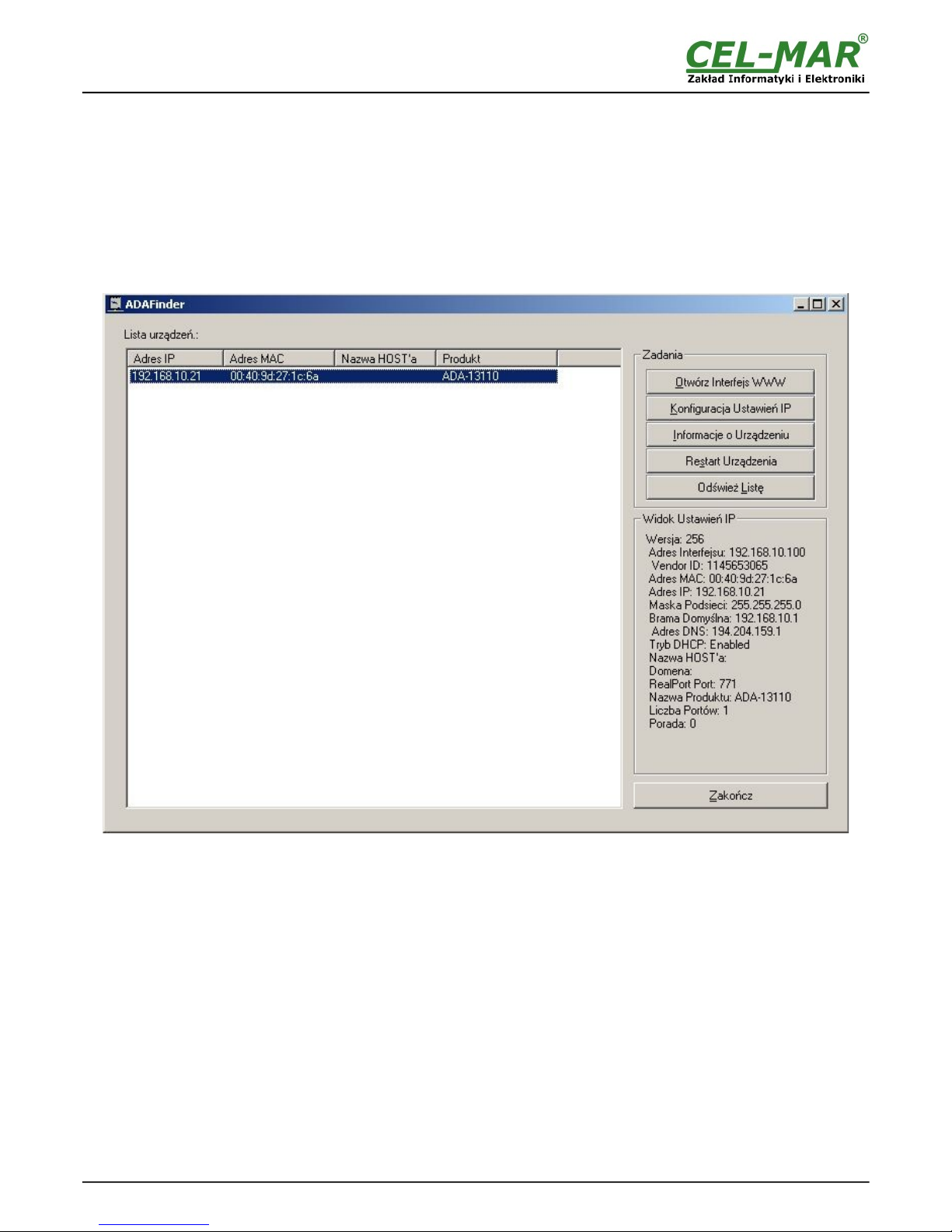
5.1. INITIAL CONFIGURATION USING ADAFINDER SOFTWARE
5.1.1. ADAFINDER INSTALLATION
The initial configuration of network setting at the converter can be made by using ADAFinder or ADAWiz software. The installation is
automatically after insert the CD (compact disc) to an optical drive. If the autorun doesn't start, should run the file setup.exe located in
main CD catalogue. After installation the software ADAFinder and ADAWiz are available in Start->Programs->CEL-MAR->ADANet.
5.1.2. NETWORK SETTING
ADAFinder is use for initial configuration of converter's network setting.
Before running ADAFinder should be disabled the System FireWall!
After running, the program is searching local network and if find ADA-13110, will add them to the list of available converters [Devices:]
Fig.10.
Fig 10. Base configuration network by the use ADAFinder software
To change the network setting of ADA-13110, should:
– select the converter from the list [Devices:] and press [Configure IP Settings ],
– in windows [Set IP Address] select option 'Automatically obtain network settings via DHCP' (default setting) or 'Manually
configure network setting'. In case of manual configuration should be enter IP Address of the converter, Subnet Mask, Default
Gateway and the Password (default: dbps) of the ADA-13110 administrator for authorization of changes.
– press [Apply], configuration will be saved to the converter and will restart. After message 'Operation made successfully', press
[Refresh List] in ADAFinder window. After re-searching the lists of available converters [Devices:] will be refreshed.
Other buttons of the program main menu:
– selecting the converter from the list and pressing [Reboot Device], will make programmable reset of the converter – new
configuration of network setting will be activated,
– selecting the converter from the list and pressing [Device Information], will show an information about setting of the converter,
– selecting the converter from the list and pressing [Open Web Interface], will run Internet browser and open the configuration page
of the converter.
11
ADA-13110
Page 12
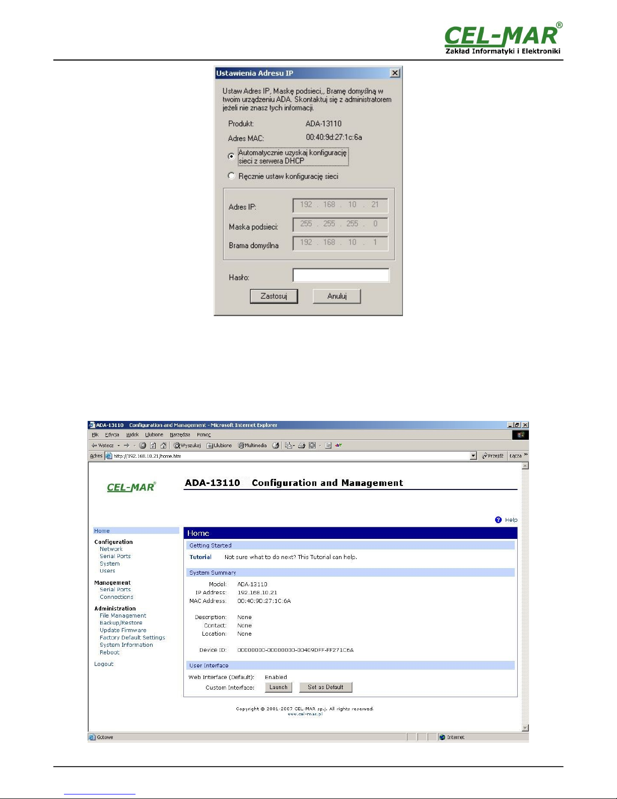
Fig 11. ADAFinder configuration of IP network address
5.2. CONFIGURATION AND MANAGEMENT BY THE USE OF INTERNET BROWSER
Integrated WWW server to ADA-13110 enable to easy configuration and diagnostics of LAN and WAN network devices by the use
Internet browser.
For configuration open the Internet Browser and type the address http://<ip-converter-address>/admin/administration.htm. The
login windows will open. Enter User name and Password as follows:
User name: root
Password: dbps
If the User name and the Password are correct, will open the page as below.
Fig 12. The web page for configuration and management of ADA-13110
12
ADA-13110
Page 13
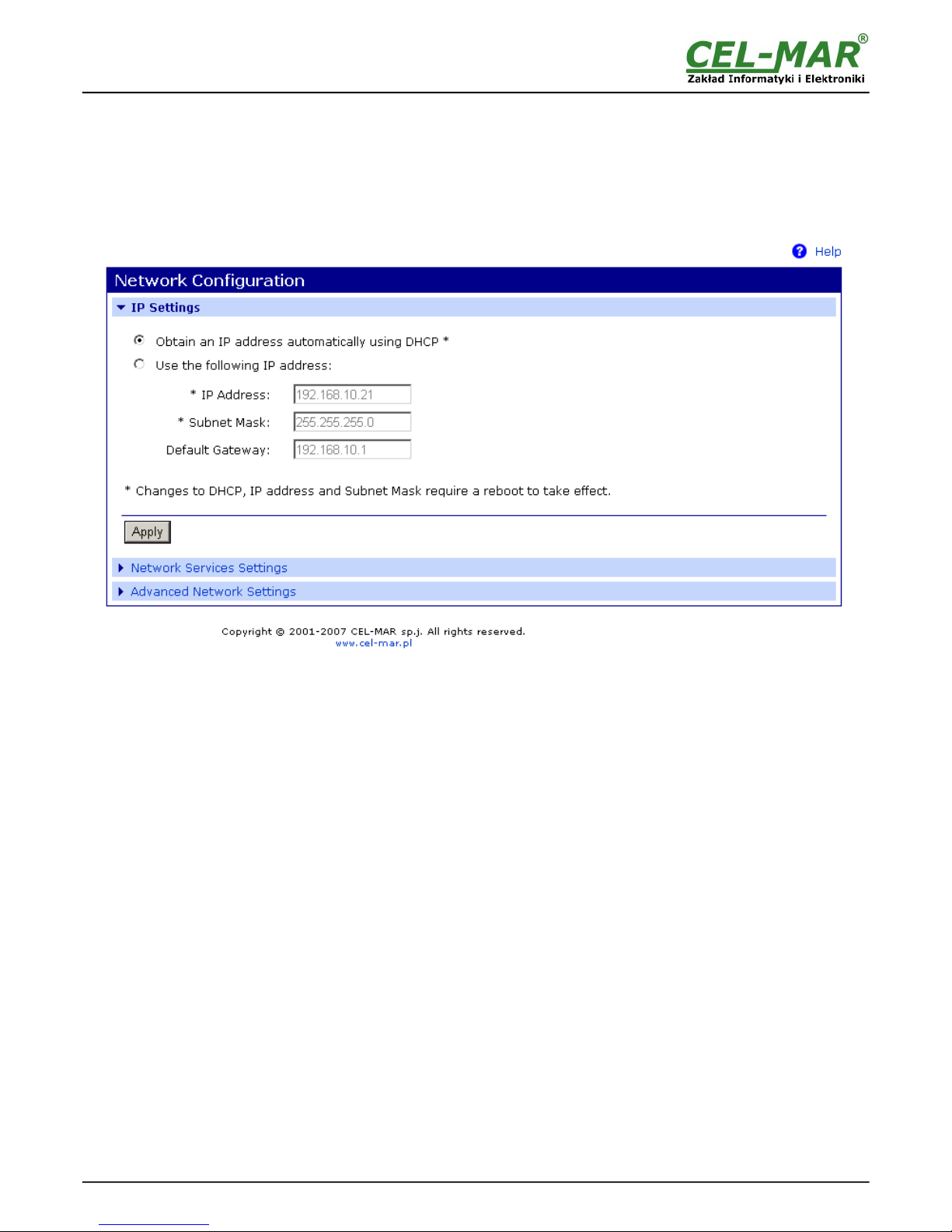
5.2.1. NETWORK CONFIGURATION
To make changes of default setting or new configuration of ADA-13110, select on left panel Configuration -> Network and then on
right [IP Settings] (Fig.13) and make the selection: Obtain an IP address automatically using DHCP or Use the following IP
address (in this option, enter IP Address of the converter, Subnet Mask, Default Gateway), press [Apply] for save. After the message
Changes have been saved successfully, from left menu select Administrator -> Reboot on right press [Reboot], will be
programmable reset of the converter and new configuration of network setting will be activated.
Fig 13. The web page for network setting of ADA-13110
5.2.2. SERIAL PORT CONFIGURATION
The configuration of serial port of ADA-13110 converter includes: port description, setting of port profile (operating mode) and setting
of serial transmission parameters (baud rate, data bits, parity, stop bits).
Select on left panel Configuration -> Serial Ports and then on a page Serial Port Configuration select [Port 1], will open the
configuration details page, includes:
– Port Profile Settings,
– Basic Serial Settings,
– Advanced Serial Settings,
5.2.2.1. SERIAL PORT PROFILE CONFIGURATION (OPERATING MODE)
Select on right panel Serial Port Configuration -> Port Profile Settings and then press Change Profile... will open the page Select
Port Profile for selection of available port profiles (fig. 14).
Configuration of profile used in typical solutions will be presented in next chapters.
The ADA-13110 operates properly in profiles as follows:
– RealPort
– TCP Sockets
– UDP Sockets
– Serial Bridge
Configuration of profiles will be presented in next chapters.
13
ADA-13110
Page 14
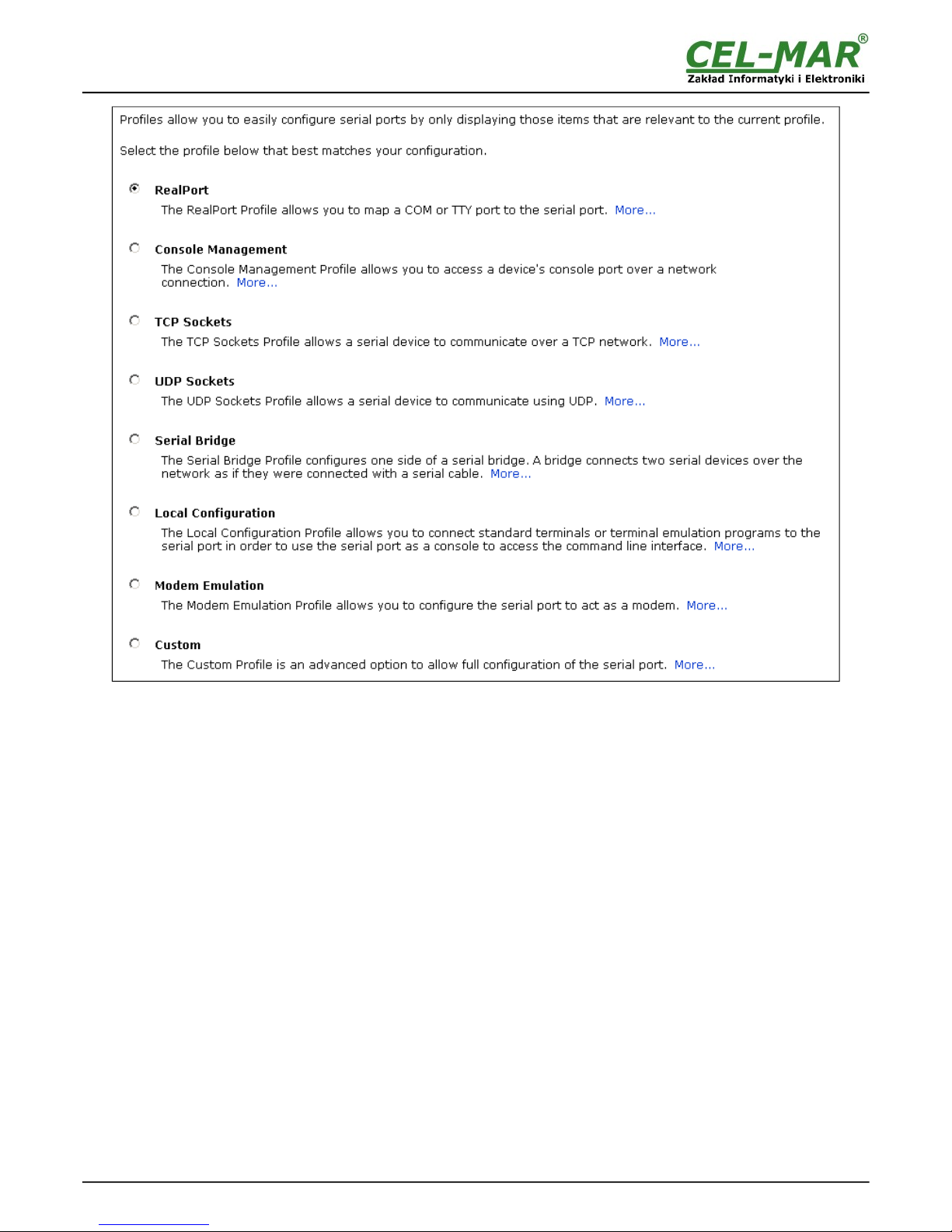
Fig 14. Selection serial port profile web
5.2.2.1.1. REALPORT (VIRTUAL PORT) CONFIGURATION
Choosing RealPort (Virtual Port, Fig. 14) is configured the serial port of ADA-13110, for communication with virtual port COM of
computer. Press [Apply] for save. After installation driver (RealPort) of virtual port COM (see chapter 6) in operating system, data
sending by application to this port are transferred through WLAN/WAN to ADA-13110 converter and are present on his serial port. The
driver RealPort installation is presented in chapter 6. Normally RealPort service allows for one connection through WLAN/WAN,
between computer and server port.
Connection from other computers to the converter will be not taken, what will cause the error message.
5.2.2.1.2. TCP SOCKETS CONFIGURATION
Choosing TCP Sockets is configured the serial port of ADA-13110, for direct communication with PC or other network device by the
use of TCP socked. Data sending by application/device to TCP socked are transferred through network to ADA-13110 converter and
are present on his serial port. To save selected configuration, press the button [Apply].
5.2.2.1.2.1. TCP SERVER & CLIENT CONFIGURATION
After saving the profile in section TCP Server Settings, set parameters:
- port for Telnet service, in standard 2001,
- port for serial port service, in standard 2101 (via this port the data are sent to serial port of server),
- port for safe access to serial port service, in standard 2601 (via this port the data are sent to serial port of server),
Additionally, there is the possibility of selection Enable TCP Keep Alive – connection will be kept, even if the data is not transmitted
over the network.
14
ADA-13110
Page 15
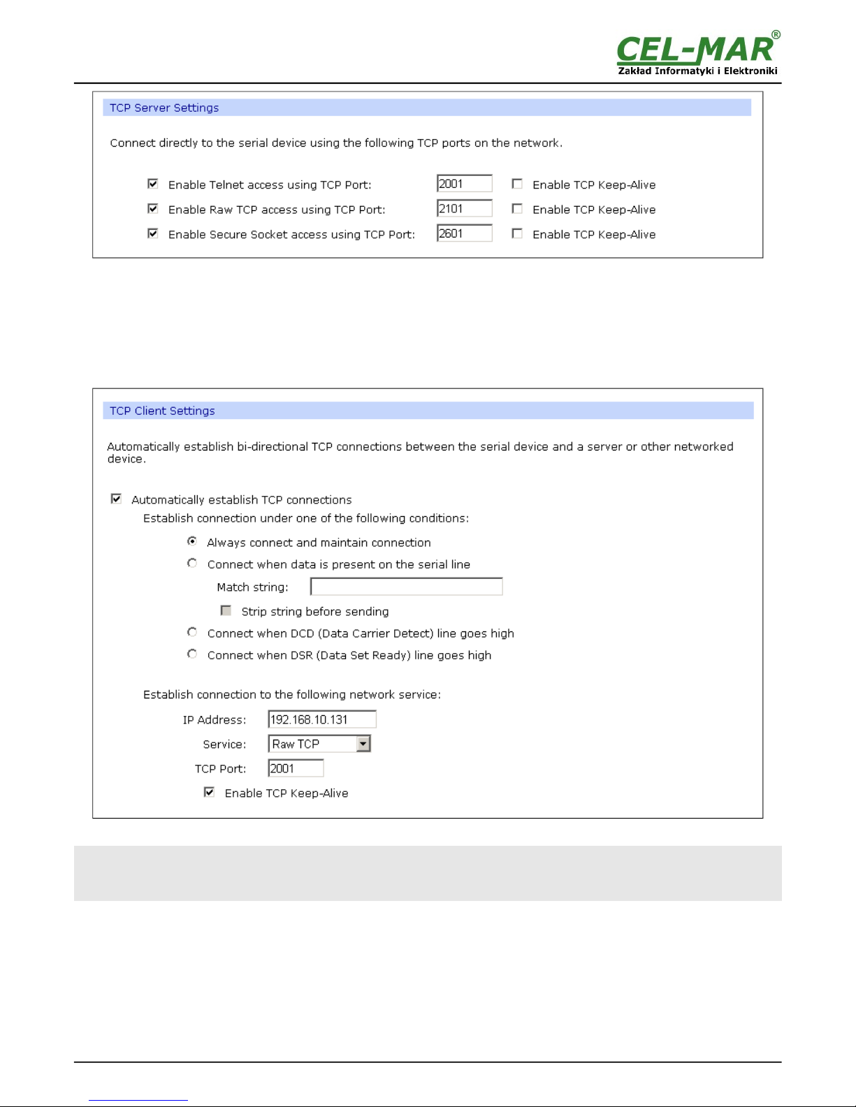
Fig 15. Example configuration of TCP server
For configuration of TCP Client Settings (TCP Client Setting, fig. below), select Automatically establish TCP connections,
connection between client and TCP server will be automatically. Then select Always connect and maintain connection option and
in section Establish connection to the following network service enter IP address of device to which TCP client will send data,
select service and enter port. There is also possible to select an option Enable TCP Keep-Alive – connection will be kept, even if the
data is not transmitted over the network.
For saving the configuration press [Apply].
Fig 16. Example configuration of TCP client
ATTENTION !
Default port of serial port service is 2101.
If on the local network is conflict with other network service using the same port, in the converter's port configuration
change number of port into another for the server and client service .
5.2.2.1.2.2. THE 'ENABLE TCP KEEP-ALIVE' OPTION CONFIGURATION
Option Enable TCP Keep-Alive keeps connection between server and client, even if the data is not transmitted over the network and
reconnection in case of interruption.
Configuration of this option can be made by selection Configuration -> Network -> Advanced Network Settings -> TCP Keep-Alive
Settings. In this section can be configured:
– Idle Time – specifies the period of time (scope 10 sec. - 24 hours) that a TCP connection has to be idle before a keep-alive is sent.
– Probe Interval – the time in seconds between each keep-alive probe (scope 10 – 75 sec.),
– Probe Count – the number of times TCP probes the connection to determine (scope 5 – 30 trials).
15
ADA-13110
Page 16
5.2.2.1.2.3. SERIAL PORT TRANSMISSION PARAMETERS CONFIGURATION
For proper operation of ADA-13110 with device connected to his serial port, should be set the same transmission parameters for both
devices.
Select Basic Serial Settings and enter Baud Rate, Data Bits, Parity, Stop Bits, the same parameter like has device connected to
the serial port of the converter.
5.2.2.1.3. UDP SOCKETS CONFIGURATION
Choosing UDP Sockets is configured the serial port of ADA-13110 converter for direct communication with PC or other device
connected to the network by the use of UDP socked. Data sending by application or other device/s to this port are transferred through
LAN/WAN to ADA-13110 converter and are present on his serial port. Press [Apply] for save the configuration.
5.2.2.1.3.1. UDP CLIENT & SERVER CONFIGURATION IN CASE OF MASTER DEVICE
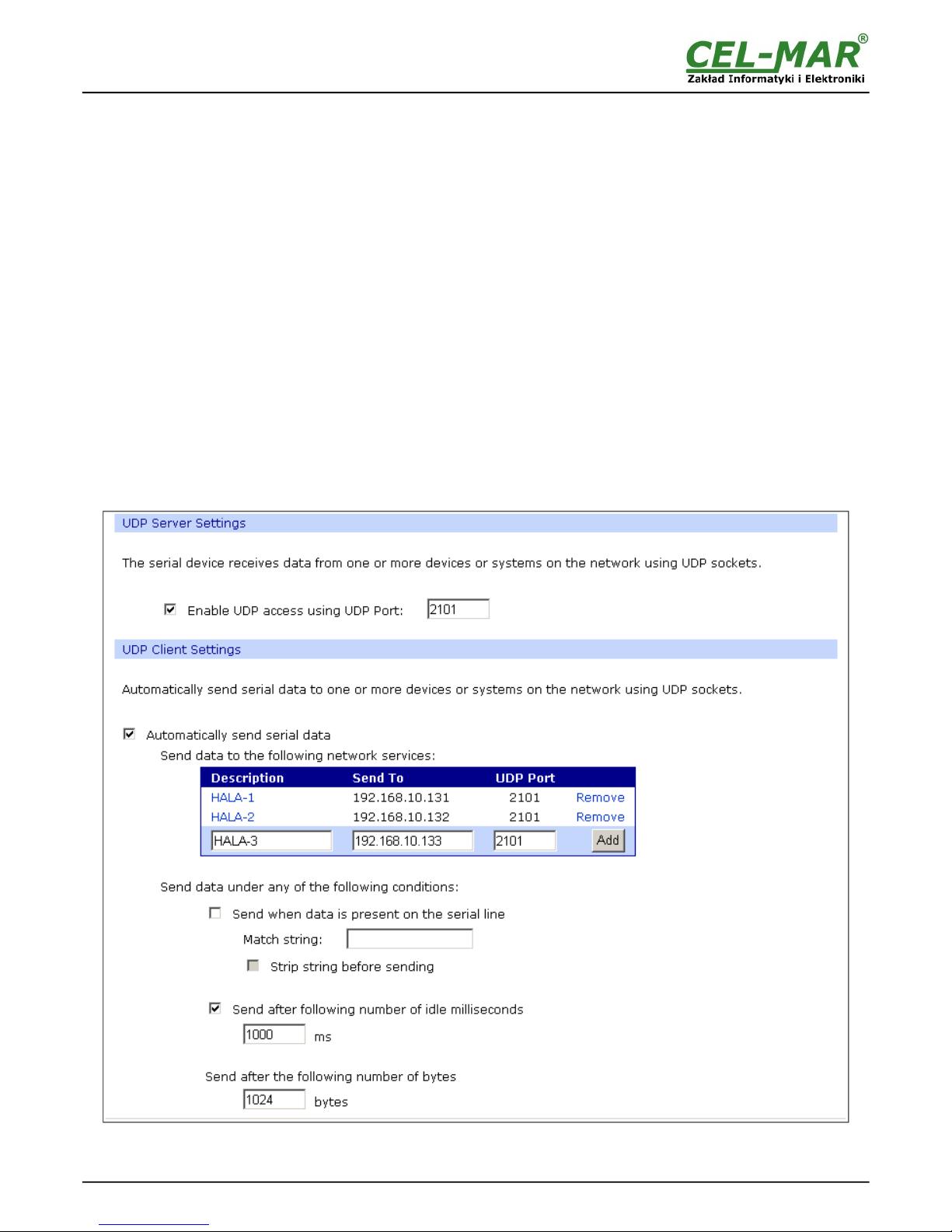
After saving the UDP Sockets profile, will open section UDP Server Settings with operating parameters like on picture below. Set
access to UDP server on e.g. 2101 port. Then select Automatically send serial data in section UDP Client Settings, this
automatically send received data by the use UDP client service to the SLAVE device connected to LAN/W AN through e.g. ADA-13021
ADA-13020, ADA-13028L, ADA-13040MG, ADA-13110, ADA-14040, ADA-14040.
On lists Send data to the following network services are addresses of network devices and ports to which will be send data. In
fields:
– Description - enter e.g. location of the converter and SLAVE device,
– Send To - enter IP address of e.g. converter, connected to SLAVE device,
– UDP Port - enter the number of port on which is working UDP Server of converter connected to SLAVE device
In the section Send data under any of the following conditions is recommended to set parameters like on picture bellow.
For saving the configuration of UDP client and server for MASTER device, press [Apply].
Fig 17. Example configuration of the UDP server&client on converter connected to MASTER device
16
ADA-13110
Page 17
5.2.2.1.3.2. UDP CLIENT & SERVER CONFIGURATION IN CASE OF SLAVE DEVICE
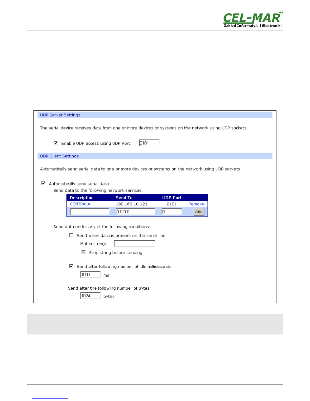
Set operating parameters of UDP server on the converter connected to SLAVE device eg. like on picture below. Set access to UDP
server on e.g. 2101 port. Then select Automatically send serial data in section UDP Client Settings, this automatically send
received data by the use UDP client service to the MASTER device connected to LAN / WAN through e.g. ADA-13020, ADA-13028L,
ADA-13040MG, ADA-13110, ADA14040, ADA-14040.
On lists Send data to the following network services are addresses of network devices and ports to which will be send data. In
field:
– Description - enter e.g. location of the converter and MASTER device,
– Send To - enter IP address of converter connected to MASTER device,
– UDP Port - enter the number of port on which is working UDP Server of converter connected to MASTER device
In the section Send data under any of the following conditions is recommended to set parameters like on picture bellow.
For saving the configuration of UDP client and server for SLAVE device, press [Apply].
Fig 18. Example configuration of the UDP server&client on converter connected to SLAVE device
ATTENTION !
Default port of serial port service is 2101.
If on the local network is conflict with other network service using the same port, in the converter's port configuration
change number of port into another for the server and client service .
17
ADA-13110
Page 18
5.2.2.1.3.3. SERIAL PORT TRANSMISSION PARAMETERS CONFIGURATION
For proper operation of ADA-13110 with device connected to his serial port, should be set the same transmission parameters for both
devices.
Select Basic Serial Settings and enter Baud Rate, Data Bits, Parity, Stop Bits, the same parameter like has device connected to
the serial port of the converter.
5.2.2.1.4. SERIAL BRIDGE PROFILE CONFIGURATION
Choosing the Serial Bridge profile enable direct communication between two devices connected to two ADA-13110 converters over
the network as if they were connected with a serial cable. A properly configured ADA-13110 will start automatically communication
with each other. Press [Apply] for save the configuration
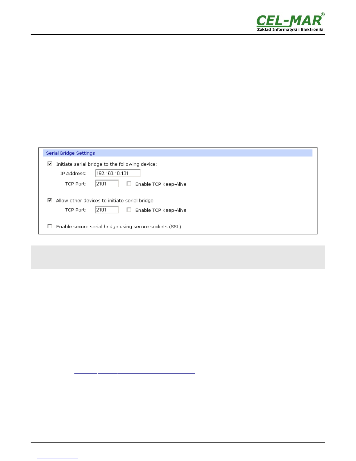
After saving the Serial Bridge profile, will open section Serial Bridge Settings (fig. below) with operating parameters like on picture
below. Select Initiate serial bridge to the following device option and enter IP address and 2101 port of the converter with which to
create the serial bridge over the network. Additionally, can be selected [Enable TCP Keep-Alive] option which keeps connection even
if the data is not transmitted. Select Allow other devices to initiate serial bridge and enter 2101 port on which other the converter
will automatically start communication and can be set also [Enable TCP Keep-Alive] option which keeps connection even if the data
is not transmitted.
Fig 19. Example configuration of TCP Serial Bridge
ATTENTION !
Default port of serial port service is 2101.
If on the local network is conflict with other network service using the same port, in the converter's port configuration
change number of port into another for the server and client service .
5.2.2.1.4.1. SERIAL PORT TRANSMISSION PARAMETERS CONFIGURATION
For proper operation of ADA-13110 with device connected to his serial port, should be set the same transmission parameters for both
devices.
Select Basic Serial Settings and enter Baud Rate, Data Bits, Parity, Stop Bits, the same parameter like has device connected to
the serial port of the converter.
5.2.3. SYSTEM SETTINGS
Select on left panel menu Configuration -> System and then on right will be selections as follows:
– Device Identity Settings – allows adding name of converter, describe the location and add identification number,
– Simple Network Management Protocol Settings (SNMP) – allows making the configuration of management protocol SNMP.
5.2.4. USERS CONFIGURATION
On the configuration page Users are two sections:
– Users
– Configure Users
The section Users allows configuring the method of login to ADA-13110. Selecting the option Enable user logins means that after
enter the address http://<ip- c on v erter- address >/admin/administration.htm to internet browser, will open login window and will be
necessary to enter user name and password.
The section Configure Users allows adding additional user, change password, configure access and permissions for each defined
users.
5.2.4.1. CHANGING USER MANE AND PASSWORD
Changing the default user root and password, can be done as follows :
1. press user mane root in section Users Configuration->Configure Users,
2. enter new user name and password.
3. press [Apply] for saving.
18
ADA-13110
Page 19

5.2.4.2. ADDING NEW USER WITH LIMITED PERMISSIONS FOR CONFIGURATION OR
MANAGEMENT
For adding new user with limited permissions for configuration or management of the converter, follow the steps below:
1.From menu Configuration select Users,
2. In section Configure Users, press [New...],
3. Enter user mane (eg. admin) and password – twice, and press [Apply],
4. Will open the page Users Configuration, where in section Configure Users, will be new user name.
Now it is possible to configure access permissions to the converter and permissions for configuration of this new user.
Configuration of access to converter:
1.From menu Configuration select Users,
2. In section Configure Users, select added user eg. admin,
3. Will open the page User Configuration – admin, where are sections:
A/ User Configuration – possibility of rename user and password,
B/ User Access - method of access to converter from the network:
Allow command line access – access using the Command Line Interface - telnet,
Allow web interface access – access using the internet browser.
C/ User Permissions - user permissions to configuration and management of the ADA-13110 converter, where are options:
None - no permission,
Read - permission to read,
Read Self - permission to read own settings, but not other users.
Read/Write - full permission to read and write the setting.
Read/Write Self - permission to read and write own setting, but not other users.
Read All/Write Self - permission to read the setting for all users and modify only own setting (not other users).
Execute - permission to execute (start).
4. All changes are saved by pressing [Apply].
5.2.5. MANAGEMENT
On left panel in menu Management are to sections :
- Serial Ports
- Connections
5.2.5.1. SERIAL PORTS MANAGEMENT
Section Serial Ports allows to identification connections/disconnection to the serial port of the converter through the network.
5.2.5.2. CONNECTIONS MANAGEMENT
Section Connections allows to identification connections/disconnection to the converter through the network.
5.2.6. ADMINISTRATION
The menu Administration allows :
– to delete/upload files with Java applet,
– to backup/restore configuration of converter,
– to update Firmware,
– to restore the factory default settings,
– to display system details information,
to reboot the converter.
5.2.6.1. FILE MANAGEMENT
Section File Management enables upload and delete Web provided by manufacturer. Uploaded index.htm or index.html allows to
automatically run the page in the web browser after entering http://ip-converter-address/FS/WEB/index.htm and login to ADA13110
5.2.6.2. BACKUP & RESTORE CONFIGURATION
Section Backup/Restore enables backup to file or restore from file the user configuration of the converter.
5.2.6.3. FIRMWARE UPDATE
Section Update Firmware enables to make the update firmware form the file. Firstly should be done update the POST software before
updating the firmware – more details available on the web page http://www.cel-mar.pl
5.2.6.4. FACTORY DEFAULT SETTINGS
The converter was configured by the manufacturer.
To restore factory default settings, select from menu Factory Default Settings. After that the converter will automatically reboot.
5.2.6.5. SYSTEM INFORMATION
Section System Information displays:
- General – device model, MAC address, firmware version, Boot version, POST version and more.
- GPIO – not applicable in ADA-13110.
- Serial – port description, current settings of serial port, status of controlling lines and the statistics data transfer through the serial
port.
19
ADA-13110
Page 20

- Network – show statistics of ETHERNET interface for IP, TCP, UDP, ICM protocols.
5.2.6.6. REBOOT
Section Reboot allows making software reset of ADA-13110. Pressing [Reboot] will start rebooting of server during 1 min.
5.2.6.7. LOGOUT – ENDING MANAGEMENT AND CONFIGURATION
After completion of the configuration or administration should be pressing Logout on left panel – logout from WWW server of ADA13110 converter.
6. USING VIRTUAL PORT SERVICE [REALPORT]
6.1. VIRTUAL PORT DRIVER INSTALLATION IN WINDOWS XP
The installation of virtual serial port drivers should be done for the CD, by choosing:
– Win Server-2003-2008-2012
– Win-2000
– Win-98-ME
– Win-NT4.0SP5
– Win-Vista
– Win-XP-7-8
Installation of Virtual serial port drivers is as follows:
1. connect the ADA-13110 to ETHERNET network and to power supply (see p.3.2.1 - 3.2.2.),
2. press [Start] and select [Run...],
3. in the dialog window [Run] press [ Browse ],
4. select „My computer” and CD-Rom with „ADANET_DRV”,
5. select catalog Drivers/Windows/Win-XP-7-8,
6. select file „Setup.exe” for 32-bits system or „Setup64.exe” for 64-bits and press [Open],
7. when the installation window will appear press [Next],
8. will start the searching for the wireless serial servers in the network, founded devices will be added to the list.
9. select the wireless serial servers from the list for installation of virtual port driver and press [Next].
10. in window Describe the device select or not the Starting Com port and press [Finish]. The driver will be installed.
The Virtual Serial Port Drivers can be installed without connection of ADA-13110 to ETHERNET network and it is as follows:
1. press [Start] button, select [Run...]
2. in the dialog window [Run] press [ Browse ]
3. select „My computer” and CD-Rom with „ADANET_DRV”.
4. select catalog Drivers/Windows/Win-XP-7-8.
5. select file „Setup.exe” for 32-bits system or „Setup64.exe” for 64-bits and press [Open].
6. when the installation window will appear press [Next] .
7. will start the searching for converters in the network.
8. if no devices were not found press [Next].
9. should be set in the window Describe the device:
– IP address for wireless serial server,
– number of installing COM port (No. Ports)
– Starting COM
and press [Finish]. The driver will be installed.
In this way installed virtual port can require the configuration in case of connecting the wireless serial server to network.
6.2. REALPORT CONFIGURATION IN WINDOWS XP
After installation of RealPort drivers, can be done the configuration by the use the Device Manager of Windows and it is as follows:
1. Press [ Start ], select [ Properties/Setting ], press [ Control Panel ].
2. Double click icon [ Administrative Tools] and [ Device Manager ]
3. Press [Ports (COM & LPT)]. On fig. 20 are shown available serial ports COM1, COM2 and COM3 marked as ADA-13110 which
was created after installation of RealPort driver.
4. Then select [Multi-port Serial Adapter], there will be the name ADA-13110,
5. Double click the name and the window [Properties] will appear.
6. Select [Advanced] and press [Properties].
7. Enter new name of virtual port for wireless serial server. In the window [Advanced Properties] click [ADA-13110] and then
select [Properties], press [Rename Ports], now it is possible to change the name of virtual port driver for example COM5, COM11
etc. To accept the changes press [OK].
8. Select IP address, MAC, DNS server for communication with virtual port driver . In the window [Advanced Properties] click
[ADA-13110] and then select [Network] (Fig. 21), and set the IP address, MAC Address or DNS name of the wireless serial server
for communication with virtual port driver.
9. In the next window press [OK] to accept the changes.
20
ADA-13110
Page 21
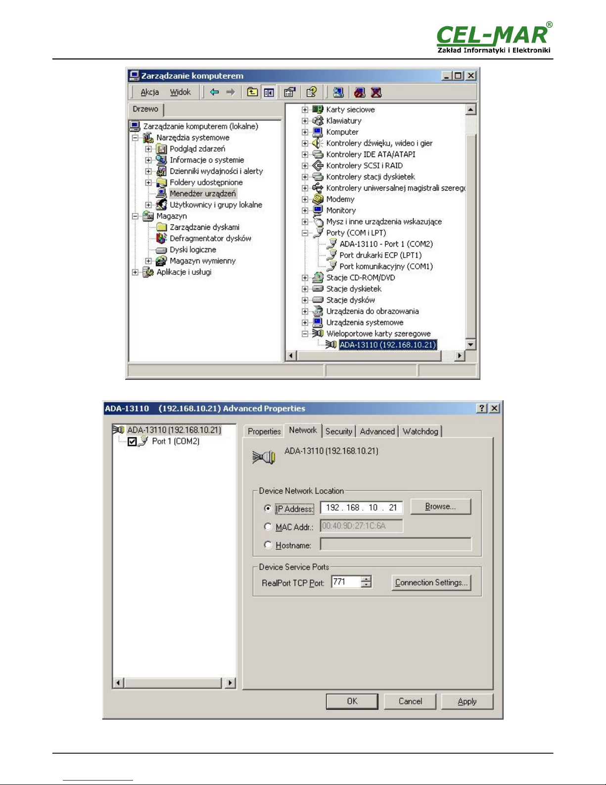
Fig 20. Devices view on Windows XP
Fig 21. Example configuration of multi-port serial adapter
21
ADA-13110
Page 22
7. FACTORY DEFAULT
Parameter Value
User name root
Password dbps
IP address
Obtain an IP address automatically using DHCP
Operating mode RealPort
Bout rate[bits/sec] 9600
Number of data bits 8
Parity Control no
Number of stop bits 1
Flow Control no
8. TROUBLESHOOTING
Problem Solution
I forgot the password Restoring Default Settings according to steps below:
1. Disconnect the power of the converter,
2. Remove the cover of ETHERNET connector,
3. Press RESET “RST” and holding the button, connect the power of the converter,
4. Release the button after 20 sec. when the converter will start with default settings.
Restoring Default Settings deletes existing configuration and the proper configuration
should be loaded to the converter from the backup.
I changed the configuration and the
converter isn't functioning.
1. Enter in the Internet browser http://converter-ip-address,
2. Select the menu [Factory Default Settings] press [Restore].
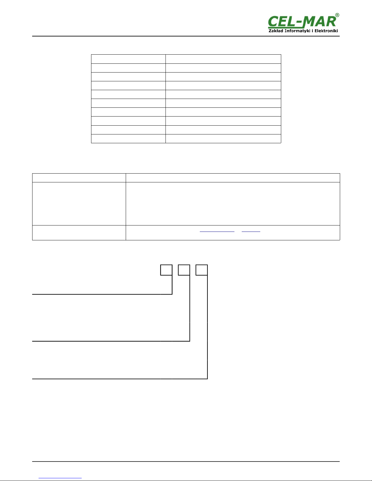
9. VERSIONS
ADA-13110 - - -
Order example:
Product Symbol: ADA-13110-1-2-3
1 – basic version of electronic,
2 – 1kV= galvanic isolation, from the power supply,
3 – cover without inlets, plug-in screw terminal block.
Electronic versions:
Basic
1
Galvanic isolation:
1kV= from the power supply
2
3kV= from the power supply
3
1kV= 3-way
23
3kV= 3-way
33
Terminal & Terminal Cover:
Cover without inlets, screw terminal block
1
Cover with inlets, screw terminal block
2
Cover without inlets, plug-in screw terminal block
3
Isolation from the power supply allows transmitting signals: Tx, Rx, RTS, CTS, DTR, DSR, DCD of RS232 interface.
3-way isolation allows transmitting signals: Tx, Rx, RTS of RS232 interface.
22
ADA-13110
Page 23
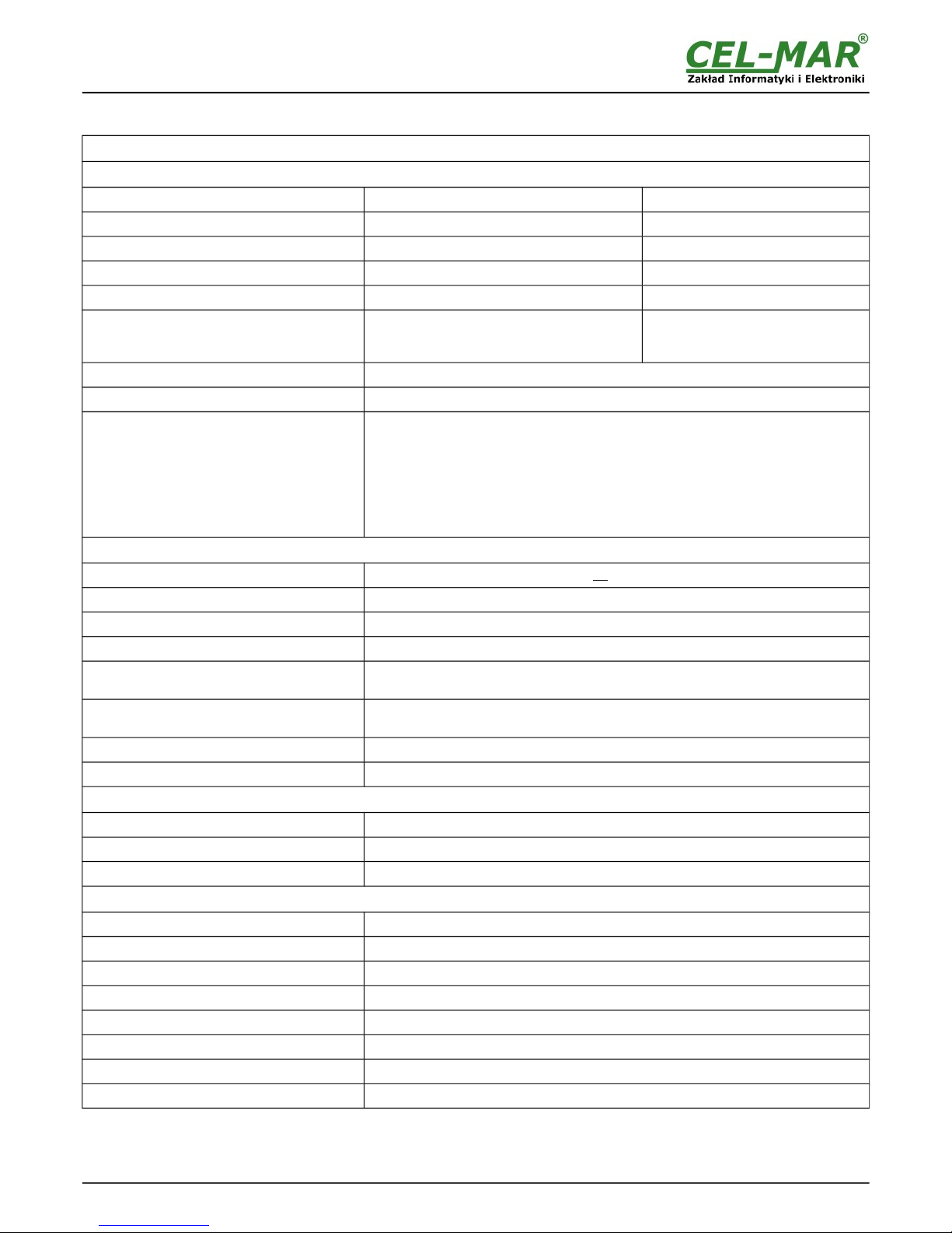
10. SPECIFICATION
TECHNICAL DATA
Transmission Parameters
Interfaces ETHERNET RS232
Connector RJ45 DB-9M (male)
Max. Line length
LAN up to 150 m Up to 15m
Max. number of connected device Depend on addressing type in network 1
Max. baud rate
10/100 Mbit/s 230,4 kbps
Transmission line
4-pair twisted cable, UTP 4x2x0,5 (24AWG),
shield inside large interferences STP 4x2x0,5
(24AWG)).
e.g. CAB-DB9F/DB9M-S-1,8m cable
Transmission type
Asynchronous transmission half duplex or full duplex.
Standards IEEE 802.3, EIA-232, CCITT V.24
Optical Signalization
• PWD green LED - power supply,
• RX red LED - receive data on RS232 port,
• TX yellow LED- transmit data on RS232 port,
• RTS yellow LED – outgoing signal on RS232 port,
• CTS red LED - incoming signal on RS232 port,
• DTR yellow LED – outgoing signal on RS232 port,
• DSR red LED - incoming signal on RS232 port,
• DCD red LED - incoming signal on RS232 port,
Electrical Parameters
Power requirements
10 - 24 – 30 V DC
Power Cable
Recommended length – up to 3m
Power
3W
Protection from reverse power polarization Yes
Galvanic Isolation
1kV= or 3kV=(between power circuit and RS232 interface),
1kV= or 3kV=(between power circuit and ETHERNET signal line)
Electromagnetic compatibility
Resistance to disruptions PN-EN 55024.
Emission of disruptions PN-EN 55022.
Safety requiring
According to the PN-EN60950 norm.
Environment
Commercial and light industrial.
Environmental Parameters
Operating temperature
-30 ÷ 60 °C
Humidity 5 ÷ 95% - non-condensing
Storage temperature
-40 ÷ 70°C
Casing
Dimensions
53mm x 90mm x 62mm,
Material
Noryl UL. 94 V-O
Degree of casing protection
IP40
Degree of terminal protection
IP20
Weight
0,10 kg
According to standards
DIN EN50022, DIN EN43880
Location during work
Free
Mounting
Rail mounting according to DIN35 standard / TS35.
23
ADA-13110
Page 24
24
ADA-13110
Dear Customer,
Thank you for purchasing CEL-MAR Company products.
We hope that this user manual helped connect and start up ADA-13110 converter. W e also wish to inform you that we are a
manufacturer of the widest selections of data communications products in the world such as: data transmission converters with
interface RS232, RS485, RS422, USB, Current Loop, Fibre-Optic Converters and Ethernet or Wi-Fi.
Please contact us to tell how you like our products and how we can satisfy you present and future expectation.
CEL-MAR sp.j.
Department of Computer Science and Electronics
Sciegiennego 219C str.
25-116 Kielce, POLAND
Tel....................................................: +48 41 362-12-46
Tel/fax..............................................: +48 41 361-07-70
Web.................................................: http://www.cel-mar.pl/en
Office...............................................: [email protected]
Sales department........................... .: s al es @cel-mar.pl
Technical information ..................... : [email protected]
 Loading...