

Page 1

Narrowband Multi-channel
Data Radio Modem
LinkWiser™-S400M
Technical data & Users’ Manual
Page 2

Technical Datasheet
&
User’s Manual
Narrowband multi-channel data radio modem
LinkWiser™-S400M
Cellution Inc.
#317, NKIC, 48-84 Honguen-1dong, Seodaemun-gu, Seoul, Korea Zip: 120-760
Enquiries: [email protected]
Voice: +82-2-3217-4838 / Fax: +82-2-3217-4831
2
INDEX
1. REVISION HISTORY...................................................................................................................................... 3
2. PRODUCT OVER V I EW ..................................................................................................................................3
2-1. PICTURE....................................................................................................................................................... 4
3. BLOCK DIAGRAM......................................................................................................................................... 4
4. FEA TURES........................................................................................................................................................ 4
5. APPLICA TIONS............................................................................................................................................... 5
6. PIN DESCRIPTIONS....................................................................................................................................... 5
7. WIRING DIAGRAM........................................................................................................................................ 6
8. MAXIMUM RATINGS.................................................................................................................................... 7
9. SPECIFICATIONS...........................................................................................................................................7
10. DIMENSION...................................................................................................................................................7
11. INTEGRATION GUIDE................................................................................................................................ 8
11-1.
COMMUNICATION RANGE................................................................................................................... 8
11-2.
ANTENNA MATCHING........................................................................................................................... 8
11-3. MODULE MODIFICATION..................................................................................................................... 8
11-4. END PRODUCT LABELING REQUIREMENTS................................................................................... 8
12. CONFIGURATION........................................................................................................................................ 9
12-1
ENTERING CONFIGURATION MODE .............................................................................................................. 9
12-1-1 Command Format
............................................................................................................................ 9
12-1-2 Configuration Commands in details
.............................................................................................. 9
12-1-3 Registers Description
..................................................................................................................... 10
12-2 TRANSPARENT MODE..................................................................................................................................11
12-2-1 Operation
..........................................................................................................................................11
12-2-2 Examples of configuration with AT commands for transparent mode
....................................11
12-3
ADDRESS MODE..........................................................................................................................................11
12-3-1 Operation
..........................................................................................................................................11
12-3-2 Examples of configuration with AT commands for address mode
.......................................... 12
12-4
EXTENDED AT COMMAND SET .................................................................................................................. 12
12-4-1 CH R/W (Channel in use).................................................................................................................. 12
12-4-2 Tx power control................................................................................................................................ 13
12-4-3 RSSI level checking............................................................................................................................ 14
12-4-4 Destination address setting................................................................................................................ 14
12-5
TIMING CHART........................................................................................................................................... 14
12-5-1 Maximum Packet Size........................................................................................................................ 14
12-5-2 Timing Chart Overview ..................................................................................................................... 14
12-5-3 UART Timing in Tx............................................................................................................................ 16
12-5-4 Air Ti ming.......................................................................................................................................... 16
12-5-5 UART Timing in Rx............................................................................................................................ 16
12-5-6 Conclusion (
TOTAL TIME CONSUMING)
........................................................................................ 16
12-6
TERMINAL SETTING............................................................................................................................. 16
Page 3

Technical Datasheet
&
User’s Manual
Narrowband multi-channel data radio modem
LinkWiser™-S400M
Cellution Inc.
#317, NKIC, 48-84 Honguen-1dong, Seodaemun-gu, Seoul, Korea Zip: 120-760
Enquiries: [email protected]
Voice: +82-2-3217-4838 / Fax: +82-2-3217-4831
3
1. REVISION HISTORY
REVISION
SIGNED DATE DESCRIPTION
1.0.0
JN Lee
15/10/2009 Document created
2. PRODUCT OVERVIEW
LinkWiser™-S400M
Narrowband multi-channel data radio modem
LinkWiser™-S400M series support a narrowband, 12.5MHz channel spacing and an exceptional
receiver sensitivity, -118dBm and is a complete wire-replacement solution (RS-232C, RS-485 ) with
multi-channel operation that enables easy to connect between DTE and LinkWiser™-S400M without
additional interface circuits. It is all that just plug into power and connect it to DTE.
LinkWiser™-S400M supports point-to-point, point-to-multi, multi-drop and repeater function in
compliances with most of wire-line based networking solutions such as Profibus, Modubus,
Pelco-D, Pelco-P, etc. and realizes LOS (Line of Sight), 1.6Km (about 1 miles) at max. 10mW
(+10dBm) output power.
LinkWiser™-S400M is ideally suitable where higher reliability and performance is required.
LinkWiser™-S400M is ideally suitable with South Korean KCC & Japanese ARIB regulations. And it
supports 400~470MHz frequency band at 12.5KHz of narrowband operation.
LinkWiser™-S400M is approved by KCC in conjunction with
LARN2-IO2S424.7125/424.9500TR0.01F1D22220 (데이터전송용, 424MHz, 20ch),
447.8625/447.9875TR0.01F1D11 (데이타전송용, 447MHz, 11ch) and
LARN3-IO447.2625/447.5625TR0.01F1D25 (안전시스템용, 447MHz, 25ch). And KCC ID is
“CE3-LinkWiserS400M.
Page 4
Technical Datasheet
&
User’s Manual
Narrowband multi-channel data radio modem
LinkWiser™-S400M
Cellution Inc.
#317, NKIC, 48-84 Honguen-1dong, Seodaemun-gu, Seoul, Korea Zip: 120-760
Enquiries: [email protected]
Voice: +82-2-3217-4838 / Fax: +82-2-3217-4831
4
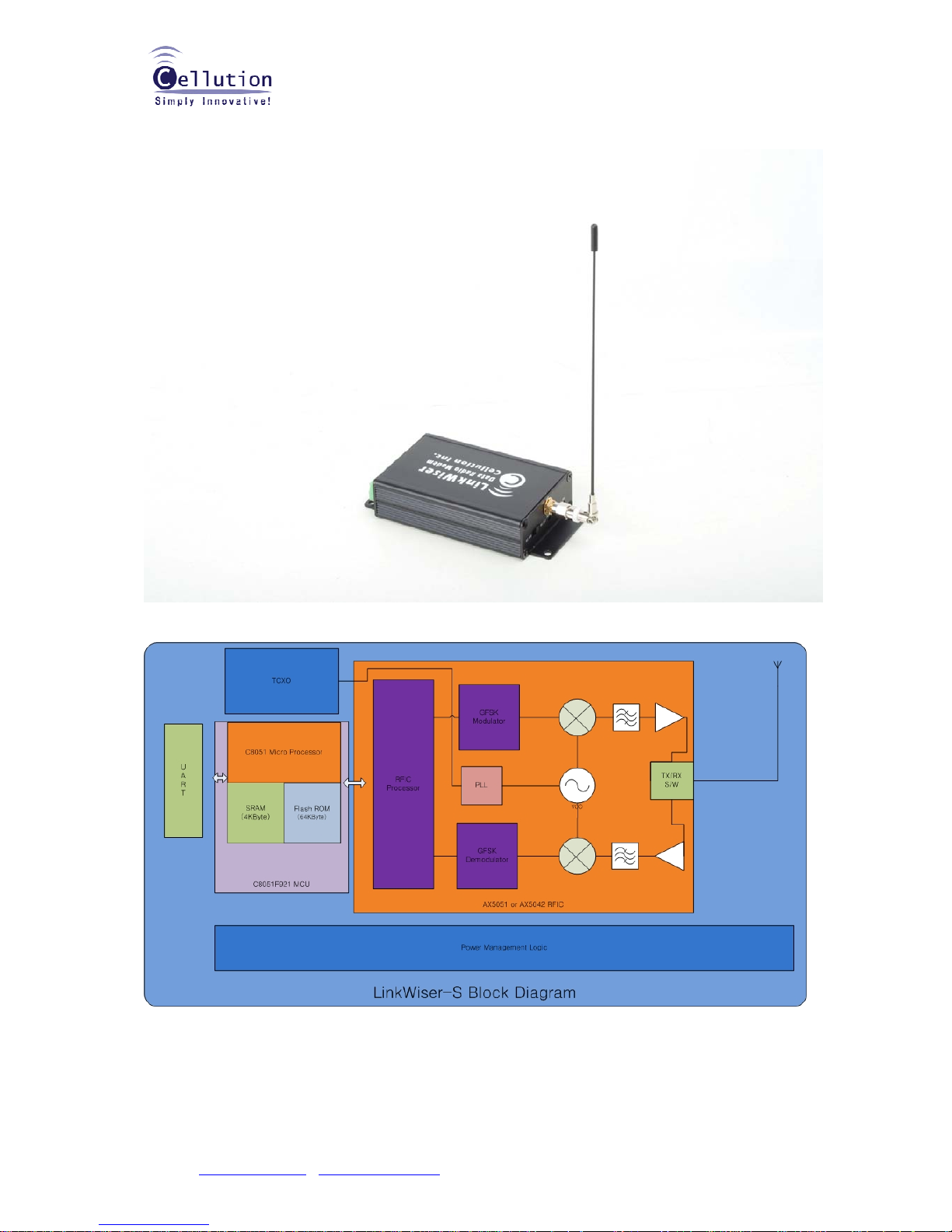
2-1. PICTURE
3. BLOCK DIAGRAM
4. FEATURES
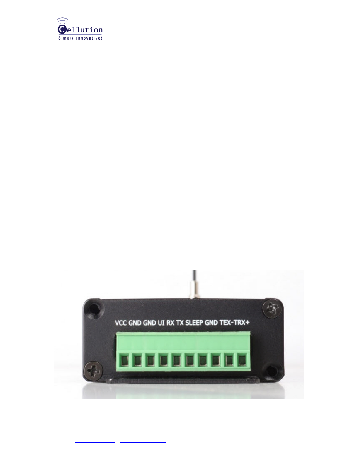
9 simple 10 pin interface
9 2 different mode (Transparent, Address) programmable
Page 5
Technical Datasheet
&
User’s Manual
Narrowband multi-channel data radio modem
LinkWiser™-S400M
Cellution Inc.
#317, NKIC, 48-84 Honguen-1dong, Seodaemun-gu, Seoul, Korea Zip: 120-760
Enquiries: [email protected]
Voice: +82-2-3217-4838 / Fax: +82-2-3217-4831
5
9 Repeater mode support
9 Easy to use AT command set
9 A few clicks only for configuratio n (No RF knowledge requirement)
9 Low power consumption for battery operation
9 Robust anti-interference HDLC protocol
9 12.5KHz of narrowband
9 424, 447MHz (Korea)
9 Exceptional sensitivity (-118dBm @ 4.8kbps)
9 Long distance communication: Up to 1 mile (1.6Km) in line of sight.
9 Operating temperature: -30 ~ 80°C
9 Programmable COM baud rate (1.2 ~ 38.4kbps)
9 Compliance with the registration regulation of the government
9 Low cost, prompt delivery and no limit to the quantity of order
5. APPLICA TIONS
9 Handheld terminals
9 Heavy vehicle/machine remote controls
9 EPOS equipment, barcode scanners
9 Data loggers
9 Industrial telemetry and telecommand
9 In-building environmental monitoring and control
9 High-end security and fire alarms
9 Vehicle data up/download
9 AMR
9 Wireless home networking
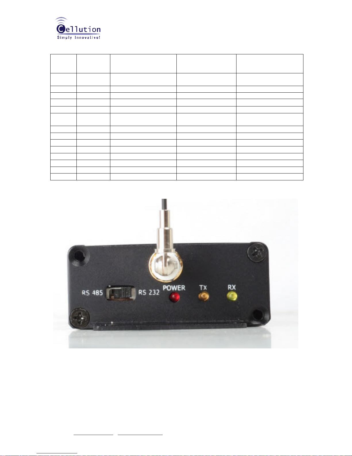
6. PIN DESCRIPTIONS
Page 6
Technical Datasheet
&
User’s Manual
Narrowband multi-channel data radio modem
LinkWiser™-S400M
Cellution Inc.
#317, NKIC, 48-84 Honguen-1dong, Seodaemun-gu, Seoul, Korea Zip: 120-760
Enquiries: [email protected]
Voice: +82-2-3217-4838 / Fax: +82-2-3217-4831
6
Item no PIN Description Level
Connected to the
terminal
DTE
(User terminal)
Remarks
1 VCC Power input 6.5VDC ~
24VDC
2 GND Power supply/Ground DGND/AGND
3 GND Power supply/Ground DGND/AGND
4 U/I User Interface
5 RX_D Serial data receiving end CMOS: TX_D RS232C
6 TX_D Serial data transmitting
end
CMOS: RX_D RS232C
7 Sleep
Sleep control (input) end
2.8V (low Active)
8 GND Power supply/Ground DGND/AGND
9 TEX- Serial data RS485
10 TRX+ Serial data RS485
7. WIRING DIAGRAM
TO BE UPDATED
Page 7
Technical Datasheet
&
User’s Manual
Narrowband multi-channel data radio modem
LinkWiser™-S400M
Cellution Inc.
#317, NKIC, 48-84 Honguen-1dong, Seodaemun-gu, Seoul, Korea Zip: 120-760
Enquiries: [email protected]
Voice: +82-2-3217-4838 / Fax: +82-2-3217-4831
7
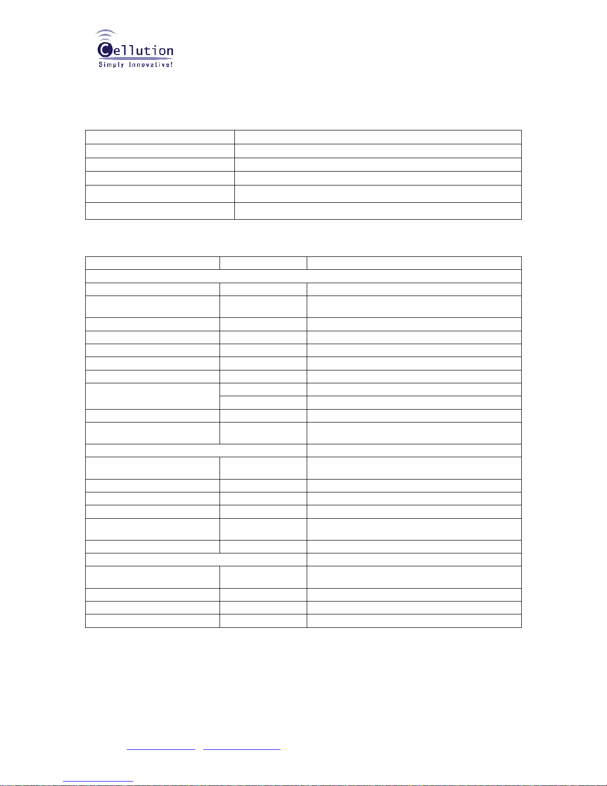
8. MAXIMUM RATINGS
Operating temperature -30°C to +80°C
Storage temperatu re -40°C to +85°C
LinkWiser™-S400M
VCC (pin 1, 2) 6.5VDC ~24VDC
9. SPECIFICATIONS
Parameter Rating Conditions
General characteristics
Communication method Half-duplex
Oscillation type
PLL Controlled
VCO
Operating frequency range 400~470MHz *see frequency table at 12 -4-1
Channel step 12.5KHz
OBW (Occupied Band Width) <8.5KHz @ 12.5KHz w 4.8kbps
Frequency stability +/- 2.0 ppm -30 to +80 °C (AFC applied)
Air data rate 4.8kbps @ GFSK w 12.5KHz, NRZI HDLC
PLL LOCK TIME (free to RX) <50us Free -> TX *1
(RX to TX) <80us RX -> TX *2
Operating voltage range 3.6V +/- 10%
Dimensions
See the below
dimension
Transmitter part
RF output power (E.R.P)
+10dBm +/- 1
dBm
Max. 13dBm available on request
TX S/N -40 dBc
Spurious emission -40 dBc < 1 GHz
-55 dBc > 1 GHz
Adjacent channel leakage
power
-37 dBc
Consumption current 80 mA @ +10dBm of Tx output power
Receiver part
Input sensitivity at Bit error
rate
-118 dBm @ 4.8kbps, NRZI HDLC w 12.5Khz channel step
Distortion -30 dB
Spurious emission -40 dBc
Consumption current Less than 80 mA
Note: * the radio section is disabling in the deep sleep mode.
10. DIMENSION
120 (H) x 60 (W) x 27 (D) mm
Page 8

Technical Datasheet
&
User’s Manual
Narrowband multi-channel data radio modem
LinkWiser™-S400M
Cellution Inc.
#317, NKIC, 48-84 Honguen-1dong, Seodaemun-gu, Seoul, Korea Zip: 120-760
Enquiries: [email protected]
Voice: +82-2-3217-4838 / Fax: +82-2-3217-4831
8
11. INTEGRATION GUIDE
LinkWiser™-S400M owns a voltage regulator which always supplies 2.8VDC to the entire circuit
except POWER APLIFIER that receives 6VDC ~ 24VDC of input voltage directly. And this is for stable
operation & performance especially in RF front end side. Nevertheless, qualified external power supply
is necessary, which must be in 6VDC ~ 24VDC with more than 40dB of ripple rejection by an external
voltage regulator .
11-1. COMMUNICATION RANGE
The communication range is a key factor to be considered. And there are some considerable variants
to get preferred communication distances.
9 Type and location of antennas in u se
9 Type of terrain and degree of obstruction of the link path
9 Sources of interference affecting the receiver
9 "Dead" spots caused by signal reflections from nearby conductive o bjects
9 Data rate and degree of filtering employed
However, our agency approved antennas must be applied to inherit our modular approval.
1 1-2. ANTENNA MATCHING
Most important for effective data transmission is selection of a good antenna, and RF grounding, both
for the transmitter and the receiver. Without a good antenna it is impossible to transmit data over a
long distance.
The LinkWiser™-S400M has the SMA connector basically. And, it doesn’t require additional antenna
matching if you purchase Cellution’s antennas.
In most cases the following basic rules will help you.
9 Connect an antenna with 50-Ohm impedance.
9 Place the antenna vertically, straight up or down from the transmitter and receiver module.
9 Do not cover the antenna with metal parts.
The connection of the metal surface of the receiver case to a larger metal part (ground plane) will
increase radiation efficiency. Such metal parts should not be placed near the antenna.
The human body can have a similar effect to metal objects. Pocket receivers should be held in the
hand and held in a position away from the body.
Best range is achieved if the transmitter and receiver antenna are in direct line of sight. Any object in
between the transmitter and receiver antenna, and metallic objects in particular, will decrease the
range.
The transmission is influenced by reflections of the transmitter signal on metallic surfaces and building.
There is possibility that data errors will occur due to overlapping of the direct and reflected signals.
11-3. MODULE MODIFICATION
The module must not be physically altered in any way.
11-4. END PRODUCT LABELING REQUIREMENTS
Pursuant to KCC (South Korea) or ARIB (Japan) regulations, the end product must be type approved.
The LinkWiser-S400M, a complete modem (+6.5VDC to +36VDC) that is type approved by South
Korean KCC.
Please contact [email protected]
for more details.
Page 9
Technical Datasheet
&
User’s Manual
Narrowband multi-channel data radio modem
LinkWiser™-S400M
Cellution Inc.
#317, NKIC, 48-84 Honguen-1dong, Seodaemun-gu, Seoul, Korea Zip: 120-760
Enquiries: [email protected]
Voice: +82-2-3217-4838 / Fax: +82-2-3217-4831
9
12. CONFIGURATION
This section describes the configuration and test commands supported by the radio module. In most
cases, once the configuration is set it will not need to be changed. Configuration is performed using a
serial terminal, or appropriate communication application.
All commands and command values accepted by the radio module are described in this section; any
entries other than those listed here results in an invalid command or argument error message.
The first step to configuring the Radio Module is to put it in Configuration Mode.
12-1 Entering Configuration Mode
A series of three consecutively typed characters, called an escape sequence, forces the radio module
to exit data transfer mode and enter the module configuration mode. While in Configuration Mode,
you can communicate directly with the radio module using a number of specific commands to
configure and test the radio module.
The escape sequence is factory set to ‘+++’ (No carriage return key is followed). A pause length of
which is called the escape guard time (about 1s) must be completed both before and after when
escape sequence is entered. These three '+' characters must not be sent as one continued frame. The
delay between 2 characters must be between 10ms~1s for the (‘+++’) sequence. This prevents the
radio module from interpreting the escape sequence as data and the vice versa. The guard time must
also be met when the Radio Module is initially powered up.
Configuration changes are stored permanently in non-volatile memory within the Radio Module.
Exiting Configuration Mode and returning back to data transfer mode is accomplished by typing “ATO”
at the command prompt. This will force a soft reset of the Radio Module resulting in any configuration
changes taking effect.
12-1-1 Command Format
LinkWiser™ module’s parameters are set through the use of AT type commands sent on the serial link.
'AT' commands complies with Hayes protocol used in PSTN module standards. This ‘AT’ protocol is
used to configure the module parameters, based on the following principles:
A data frame always begins with the two ASCII ’AT’ characters, standing for ‘ATtention’, Commands
are coded over one or several characters and may include additional data.
A given command always ends up with a < CR> Carriage Return.
AT COMMAND ADDITIONAL DATA <CR>
Note: The delay between 2 characters of the same command must be less than 30 seconds.
All alphabetical characters typed in configuration command mode are converted to upper case before
being interpreted by the configurator. Thus commands can be typed using either upper or lower case.
Despite its similarity to standard telecommunication module, it remains a radio link module and is
consequently fitted with some particular and specific ‘AT’ commands proper to radio transmission (I.e.
communication channel, radio rate...).
12-1-2 Configuration Commands in details
+++
Configuration
mode Command
Configuration Mode Activation ‘+++’ Command gives an instant access to the
module’s parameters configuration mode (AT mode). ‘+++’ Command should
be entered one by one. The time between two ‘+’ must be between 10ms
~1s. Answer: > Description
ATO Communication mode activation ‘ATO’ command gives an instant access to
the module’s Operating mode. ‘ATO’ command is used to get out of
Configuration Mode. Answer: Good Bye!
Page 10
Technical Datasheet
&
User’s Manual
Narrowband multi-channel data radio modem
LinkWiser™-S400M
Cellution Inc.
#317, NKIC, 48-84 Honguen-1dong, Seodaemun-gu, Seoul, Korea Zip: 120-760
Enquiries: [email protected]
Voice: +82-2-3217-4838 / Fax: +82-2-3217-4831
10
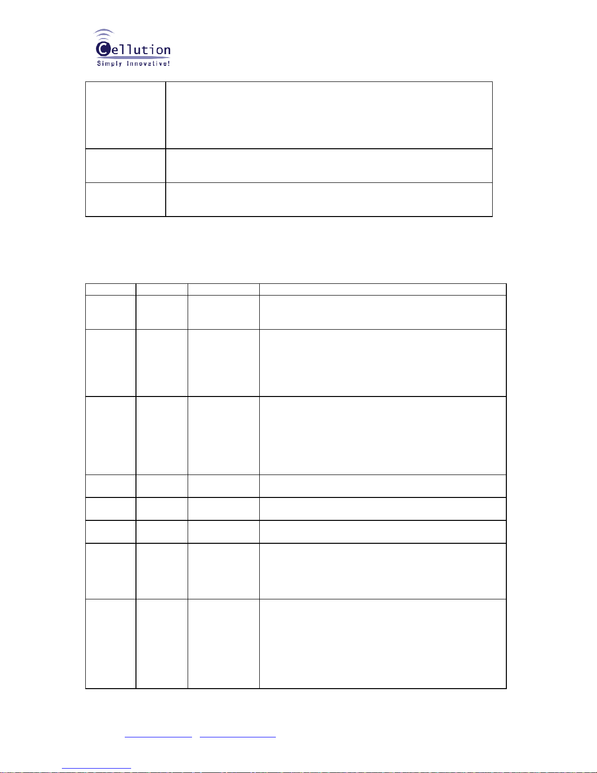
AT/V Register
Handling
Command
‘AT/V’ command displays the module’s firmware version
Ex)
AT/V<CR>
‘S424V1.0’ // LinkWiser-S, 424MHz, V1.0
‘HP915V2.0 // LinkWiser-HP, 915MHz, V2.0
AT/L ‘AT/L’ command displays a dynamic and clear status of all relevant registers of
the module with the following categories: Serial link, Radio, Operation Mode,
Network (for consumers)
AT+I Factory default
Set all registers’ values to factory default ones
12-1-3 Registers Description
The parameters to be conf igured via Conf iguration mode are stored in module’s EEPROM’s registers,
called S registers. Those registers are always listed as follows:
The standard registers and their use are shown in the next table.
Access Registers Name Description
R/W S102 Serial Link
Time Out
Indicates the value of the time-out on the serial link.
Ex): a value ‘3’ means a 3 milli sec. time out time. Refer
to the below 12-5
R/W S103 * Sleep Mode
Control *
Sleep Mode Control:
0 – Disabled (Default), module always active 1 – Enabled
If S103=1, the module will be controlled by I/O1
I/O1 = 0: Sleep Mode(power down mode)
I/O1 =1: active
R/W S104 Serial Baud
Rate
Indicates the serial baud rate with DTE:
'0': 1200 bps
'1': 2400 bps
'2': 4800 bps
'3': 9600 bps (default)
'4': 19200 bps
'5': 38400 bps
R/W S120 Network ID Network ID in 2 Bytes. Ex).: ATS120=192.168 will set the
network ID to 192.168
R/W S121 Group ID Group ID. All and only devices with the same group id
(together with the network id) will be linkable.
R/W S122 Device ID Device ID
Value Range: 1~255, Default: 1
R/W S130 Node Type Node Type
‘0’: Normal node (not intent to route a message)
’1’: Repeater node (This is a repeater, and will route any
message it received)
R/W S131 Via Repeater
Link
Via Repeater Link Control
‘0’ : Disabled
‘1’: Enabled
Ex): Assuming that S130 = ‘0’ & S131 = ‘1’, the TX data
will automatically routed to & by the repeater(address
defined by S132)
Page 11

Technical Datasheet
&
User’s Manual
Narrowband multi-channel data radio modem
LinkWiser™-S400M
Cellution Inc.
#317, NKIC, 48-84 Honguen-1dong, Seodaemun-gu, Seoul, Korea Zip: 120-760
Enquiries: [email protected]
Voice: +82-2-3217-4838 / Fax: +82-2-3217-4831
11
R/W S132 Repeater
Address
Repeater Address
Ex): Assuming that S130=’1’, this register will set the
desired repeater’s address. All data will be sent to the
repeater node first, and that repeater will automatically
route the data to the preset destination.
NOTE:
* The current firmware version (as of Oct. 08) supports a ‘SLEEP’ mode. The SLEEP mode realizes a
few mA current consumption. In this case, entire RF section is disabling where baseband is active.
12-2 Transparent Mode
The transparent mode is the default communication mode, based on null-module cable emulation.
Basically, the module in the transparent mode supports a complete wire replacement for RS-485,
RS-232 or RS-422 cable by half-duplex communication method.
This mode can be used as Point to Point or Point to Multi-point with all the modules receiving the
messages sent by any module. DTE should hold I.D recognition & generation algorithm in the USER
DATA.
12-2-1 Operation
Radio modules in transparent mode behave like wired serial links. Therefore, radio modules
automatically transmit every serial data received on their radio link, and also transmit all radio
information received on their serial link. The transparent mode can be operated for both point-to-point
and multipoint links.
The data flow control may be carried out by software applications used by various protocols such as
ProfiBus, ModBus, etc…
Consequently, the latency time is reduced to its minimum as the module no needs wait to check the
acknowledgment byte.
Any unit, with the same network ID and group ID, configured in transparent mode will receive every
radio data flowing on the same communication channel, i.e. on the same frequency.
12-2-2 Examples of configuration with AT commands for transparent mode
User +++ // Switch to Configuration mode
Module >
User ATS120=192.168<CR> // Set network ID to 192.168
Module >
User ATS121=120<CR> // set group id to 120
Module >
User ATS122=10<CR> // set device id to 10
Module >
User ATO<CR> // exit from the configuration mode
Module Good Bye!
User AT+ADDR=0 // set the operation mode to transparent mode
User DATA
12-3 Address Mode
The addressed mode is similar to a multipoint mode. All modules can communicate with each other by
addressing each frame to one of them.
12-3-1 Operation
Addressed mode’s purpose is to offer an optimal radio link performance providing the multipoint
access of the transparent mode.
Page 12
Technical Datasheet
&
User’s Manual
Narrowband multi-channel data radio modem
LinkWiser™-S400M
Cellution Inc.
#317, NKIC, 48-84 Honguen-1dong, Seodaemun-gu, Seoul, Korea Zip: 120-760
Enquiries: [email protected]
Voice: +82-2-3217-4838 / Fax: +82-2-3217-4831
12
Compared to the transparent mode, the addressed mode therefore includes the additional feature to
address each data frame to a specific module.
12-3-2 Examples of configuration with AT commands for address mode
User +++ // Switch to Configuration mode
Module >
User ATS120=192.168<CR> // Set network ID to 192.168
Module >
User ATS121=10<CR> // set group id to 10
Module >
User ATS122=10<CR> // set device id to 10
Module >
User ATO<CR> // exit from the configuration mode
Module Good Bye!
***To send data to specific I.D of same group, same network & same frequency, you have
to set AT+ADDR command before sending user data.
User AT+ADDR=16 // set the operation mode to address mode & the destination I.D is 16.
User DATA
12-4 Extended AT Command Set
This section describes the list of the extended at command set that is working on normal working
mode, not on ‘+++’ Configuration mode.
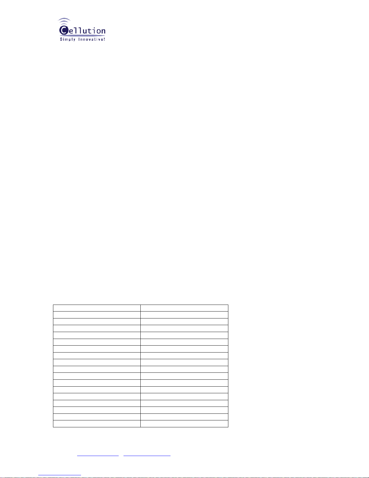
12-4-1 CH R/W (Channel in use)
Reading: ‘AT+FREQ?’
Answer: channel : 1
Freq: 424.7125MHz
Writing: AT+FREQ=5
Answer: >
Frequency channel table < LinkWiser™-S424
Frequency (MHz) Value
424.7125 1
424.7250 2
424.7375 3
424.7500 4
424.7625 5
424.7750 6
424.7875 7
424.8000 8
424.8125 9
424.8250 10
424.8375 11
424.8500 12
424.8625 13
424.8750 14
424.8875 15
424.9000 16
424.9125 17
Page 13
Technical Datasheet
&
User’s Manual
Narrowband multi-channel data radio modem
LinkWiser™-S400M
Cellution Inc.
#317, NKIC, 48-84 Honguen-1dong, Seodaemun-gu, Seoul, Korea Zip: 120-760
Enquiries: [email protected]
Voice: +82-2-3217-4838 / Fax: +82-2-3217-4831
13
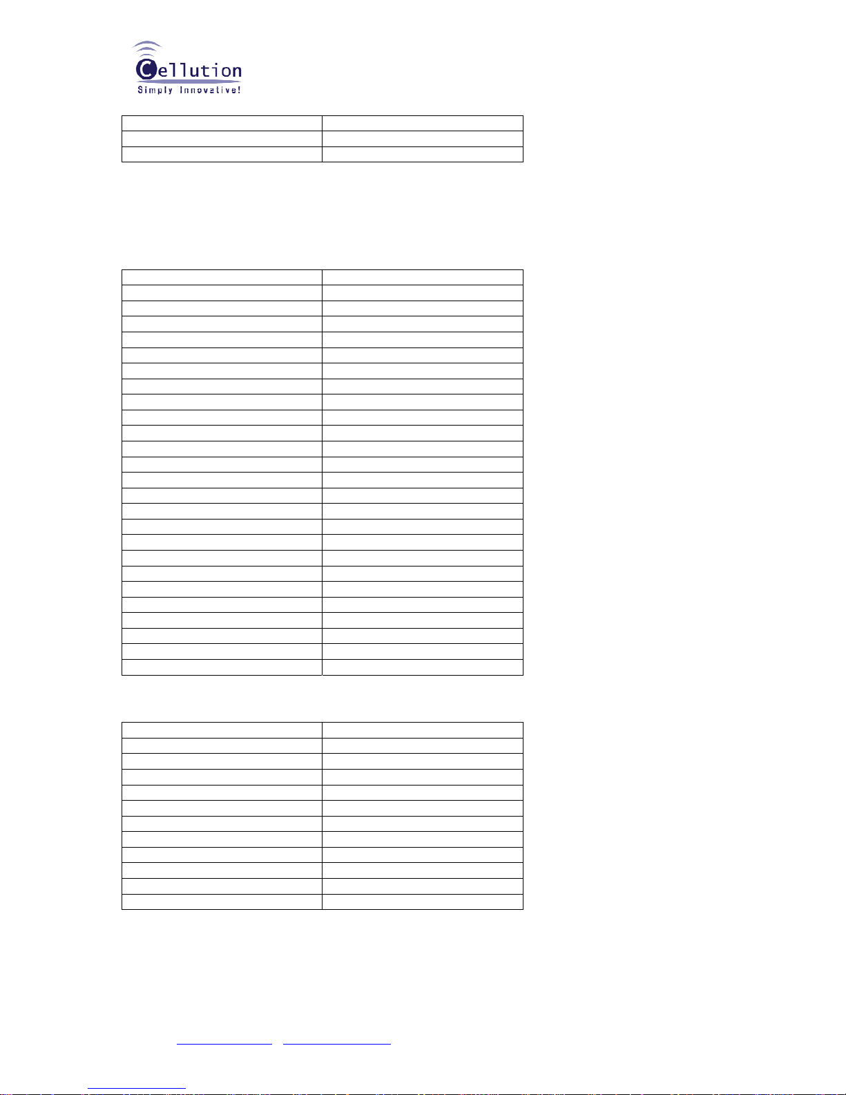
424.9250 18
424.9375 19
424.9500 20
Note:
Listen-Before-Talk (LBT) must be applied. Tx is allowed less than -100dBm of RSSI level only in all
channels.
**the continuous Tx is limited to 40 seconds only.
Frequency channel table < LinkWiser™-S447 A band
Frequency (MHz) Value
447.2625 21
447.2750 22
447.2875 23
447.3000 24
447.3125 25
447.3250 26
447.3375 27
447.3500 28
447.3625 29
447.3750 30
447.3875 31
447.4000 32
447.4125 33
447.4250 34
447.4375 35
447.4500 36
447.4625 37
447.4750 38
447.4875 39
447.5000 40
447.5125 41
447.5250 42
447.5375 43
447.5500 44
447.5625 45
Frequency channel table < LinkWiser™-S447 B band
Frequency (MHz) Value
447.8625 46
447.8750 47
447.8875 48
447.9000 49
447.9125 50
447.9250 51
447.9375 52
447.9500 53
447.9625 54
447.9750 55
447.9875 56
12-4-2 Tx power control
Reading: Reading: ‘AT+P?’
Answer: TxPower : 8
Page 14
Technical Datasheet
&
User’s Manual
Narrowband multi-channel data radio modem
LinkWiser™-S400M
Cellution Inc.
#317, NKIC, 48-84 Honguen-1dong, Seodaemun-gu, Seoul, Korea Zip: 120-760
Enquiries: [email protected]
Voice: +82-2-3217-4838 / Fax: +82-2-3217-4831
14
10dBm
Writing: ‘AT+P=8’ // Set the Tx power at 8
th
level
Answer: >
Description: Power of the Radio
Value Tx power (dBm)
8 < 10dBm
7 < 9dBm
6 < 7.9dBm
5 < 6.3dBm
4 < 4.4dBm
3 < 2dBm
2 < -1.3dBm
1 < -7.0dBm
0 < -40dBm
12-4-3 RSSI level checking
Reading: ‘AT+CSQ?’
Answer: ‘n’
Description: ‘n’ is a realistic RSSI level in the unit of ‘dBm’.
Caution: One time RSSI level reading may not be correct due to circumstances. Thus, more than three
times of RSSI level readings are recomm ended.
12-4-4 Destination address setting
Reading: ‘AT+ADDR?’
Answer: ‘n’ // n ranges 0~255
Writing: ‘AT+ADDR=n’
Description: ADDR means a destination ID, if it is set ‘0’ in the ADDR, the radio enters into the
Transparent mode. while it is set ‘1~255’ in the ADDR, the radio enters into the Address mode and
delivers data to the preset destination ID of node only.
12-5 Timing Chart
12-5-1 Maximum Packet Size
The LinkWiser accepts 128bytes of packet size of USER DATA only as its one time maximum
FIFO (First-In-First-Out) is 128bytes. If your packet size (USER DATA) exceeds over 128bytes, then
you have to split them into several appropriate size of packets with considering the below timing chart
& air rate. And also you have to put some delay between that divided packet and the packet with
considering the below timing chart & air rate in order to complete successful transmission.
12-5-2 Timing Chart Overview
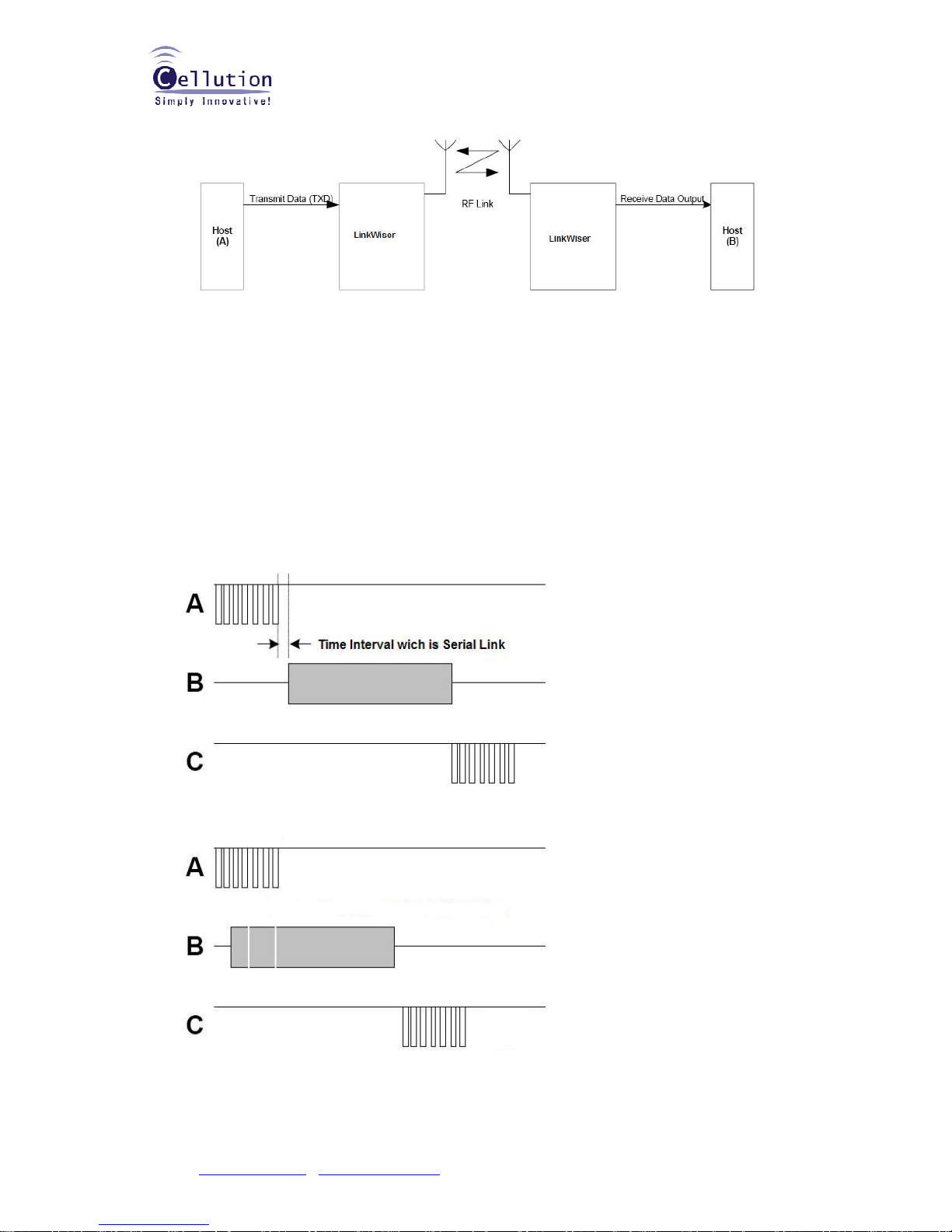
Figure1 shows a typical system block diagram comprising hosts (DTE user’s application) connected to
LinkWiser. Host(A) will be sending and Host(B) will be receiving and processing this data.
Page 15
Technical Datasheet
&
User’s Manual
Narrowband multi-channel data radio modem
LinkWiser™-S400M
Cellution Inc.
#317, NKIC, 48-84 Honguen-1dong, Seodaemun-gu, Seoul, Korea Zip: 120-760
Enquiries: [email protected]
Voice: +82-2-3217-4838 / Fax: +82-2-3217-4831
15
Figure1 Typical System Block Diagram
Data is sent and received in standard ‘RS232’ serial format and there is no restriction on characters
that may be sent.
If you configure “Serial Link Time Out” value more than one byte interval, the data flow look like
Figure2, but if you configure “Serial Link Time Out” value less than one byte interval, the data flow
looks like Figure3.
We recommend Figure2 configuration rather than Figure3 for more robust RF transmission.
Configuring “Serial Link Time Out” like Figure3 enables to split the packet into several frames and
re-packetize that frame with adding pre-defined preambles, headers and post-ambles automatically.
Thus, this case makes more overhead on RF section rather than original USER DATA eventually.
A: TX UART Timing | B: AIR RATE Timing | C: RX UART Timing
Figure2: Serial Link Time Out is more than 1byte time Interval
Figure3: Serial Link Time Out is less than 1byte time Interval
Page 16

Technical Datasheet
&
User’s Manual
Narrowband multi-channel data radio modem
LinkWiser™-S400M
Cellution Inc.
#317, NKIC, 48-84 Honguen-1dong, Seodaemun-gu, Seoul, Korea Zip: 120-760
Enquiries: [email protected]
Voice: +82-2-3217-4838 / Fax: +82-2-3217-4831
16
12-5-3 UART Timing in Tx
You MUST configure the Serial Link Time Out value depending on DEPENDING ON YOUR SERIAL
BAUD RRATE.
EX) If your serial baud rate is 9600bps, we recommend over 1ms of the Serial Link Time Out value.
Thus, you can get a result same as the above Figure2.
9600bits/second = 9600bps, then 960bytes/second because start bit & stop bit should be added.
1byte time interval in the UART section at 9600bps is around 1.042ms. And data processing time from
the LinkWiser is required. That is less than around 0.8ms. Thus, over 2ms of the Serial Link Time Out
value is recommended.
X (ms) > = 1,000 / Serial Baud Rate (bps) / 10 + 0.8
If we apply the calculation to various UART baud rates,
Over 9ms of the Serial Link Time Out value is recommended in 1200bps
Over 4ms of the Serial Link Time Out value is recommended in 2400bps
Over 3ms of the Serial Link Time Out value is recommended in 4800bps
Over 2ms of the Serial Link Time Out value is recommended in 9600bps
Over 1ms of the Serial Link Time Out value is recommended in 19200bps
12-5-4 Air Timing
Apart from the above Serial Time Out value, developers & integrators MUST recognize & calculate how
long the LinkWiser occupy a frequency to complete transmitting the USER DATA from host(s).
First of all, you have to understand that the LinkWiser doesn’t send the USER DATA as is. The
LinkWiser re-packetizes the USER DATA to transmit into the air.
Normally 51 bytes of packet overhead in case of transparent networking topology & 53 bytes of
packet overhead in case of addressing topology are required to add on USER DATA.
Thus, the calculation is as follows;
1,000 / AIR RATE (bps) / 8 = 1 Byte Time Interval (X)
Y * [ USER DATA (bytes) + 51 (Transparent) or 53 (Address) ] + 2ms (Margin) = Total Time Interval
(ms)
Ex) If air rate is 4800bps & USER DATA is 50 bytes in Transparent mode, 1 Byte Time Interval is;
= 1000 / 4,800 / 8 = 1.67msec/byte
1.67 (X) [ 50 (USER DATA) + 51 (Overhead, Transparent) ] + 2 (Margin) = around 170.67ms
12-5-5 UART Timing in Rx
There is no time interval. Thus, Z (ms) = 1,000 / Serial Baud Rate (bps) / 10
12-5-6 Conclusion (TOTAL TIME CONSUMING)
X (ms) [ 1,000 / Serial Baud Rate (bps) / 10 + 0.8 ] + Y * [ USER DATA (bytes) + 51 (Transparent) or
53 (Address) ] + 2 (Margin) + Z [1,000 / Serial Baud Rate (bps) / 10 ]
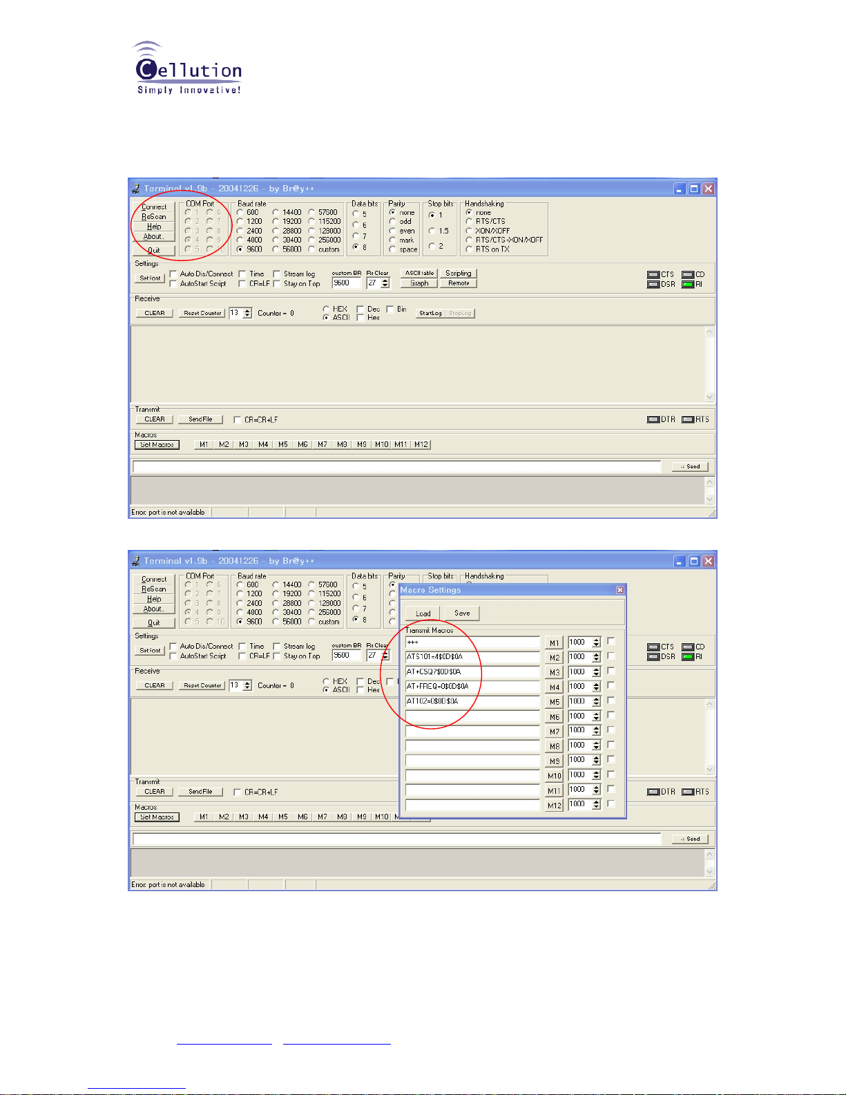
12-6 TERMINAL SETTING
A typical terminal setting
1. Please connect the LinkWiser-S400M to RS-232C in your PC.
2. Please make sure that the mode switch is set to RS-232C before power on. And also please
Page 17
Technical Datasheet
&
User’s Manual
Narrowband multi-channel data radio modem
LinkWiser™-S400M
Cellution Inc.
#317, NKIC, 48-84 Honguen-1dong, Seodaemun-gu, Seoul, Korea Zip: 120-760
Enquiries: [email protected]
Voice: +82-2-3217-4838 / Fax: +82-2-3217-4831
17
make sure that the input voltage range is within 6VDC to 24VDC.
3. Please execute the terminal program
Please click the “connect” after selection of a proper baud rate.
You can use the “Set Macros” function to make easier to write & read our AT command sets. However,
“$0D$0A” string should be followed for carriage return in this case.
 Loading...