

Page 1

Page 2

Table of Contents
1. Functions and Operating procedures of the E12 Cleo....................................................................................................................1
1.1. Modes of Operation
1.1.1 Away mode
1.1.2. Stay mode ......................................................................................................................................................5
1.1.3. Off Mode.........................................................................................................................................................6
1.1.4. Monitor Mode..................................................................................................................................................7
1.1.5. Away Monitor Mode
1.1.6. Silent Panic.....................................................................................................................................................8
1.1.7. Panic
1.1.8. Resetting the E12...........................................................................................................................................9
1.1.9. Keypad Duress
1.2. Access Control and Security
1.3. Other functions
1.3.1. Auto Arm / Disarm Time
1.3.2. GAS discharge activation option ....................................................................................................................10
1.3.3. Supervision function
1.3.4. “Power Supply Battery low” warning function
1.3.5. “Sensor Low Battery” warning function
1.3.6. Seismic detector for Panel Tamper................................................................................................................11
1.3.7. 24-Hour Test Signal
1.3.8. Signal Strength
1.3.9. Mains Failed/Restored
1.3.10. Restore Failure
1.3.11. Entry and Exit delay
1.4. Group Setup.....................................................................................................................................................................12
1.5. Outputs
1.6. Keypad
2. Description of system components
2.1. Remote control
2.2. Types of Sensors.............................................................................................................................................................13
2.2.1. Outdoor Passive Infrared Beam Sensor
2.2.2. Indoor Passive Infrared Wide Angle Sensors.................................................................................................14
2.2.3. Mini Passive Infrared High Power Sensor......................................................................................................15
2.2.4. Universal Transmitter (Door Guard)
2.2.5. Seismic Transmitter........................................................................................................................................16
2.2.6. Dual Tilt Sensor
2.3. Battery Charger, Battery (Power supply unit (PSU)) and transformer
2.4. External and internal sirens............................................................................................................................................17
3. Programming the E12
3.1. Learning in the Key Ring & Sensors
3.1.1. 3 Button Key Ring Remote
3.1.2. Outdoor Passive Infrared Sensor Long Range...............................................................................................18
3.1.3. Indoor Passive Infrared Sensor Long Range .................................................................................................19
3.1.4 Mini Indoor Passive infrared sensor................................................................................................................20
3.1.5. Mini Door Guard
3.1.6. High power door guard................................................................................................................................... 21
3.1.7. High power Seismic sensor………………………………………………………………………………………….. 22
3.1.8. High power Dual tilt sensor………………………………………………………………………………………….. 23
3.2. Associating Wireless Sensors with zones……………………………………………………………………………………. 24
3.3. Removing Wireless Sensors from zones
3.4. Associating Key rings with Users
3.5. Removing Key rings…………………………………………………………………………………………………… …………. 25
3.6. Programming Active Zones
4. Summary of SMS Commands
Appendix A:
• Wiring Diagram .......................................................................................................................................................................A.1
Appendix B:
• Reading sensors into the control panel ...............................................................................................................................B.1
Appendix C:
• Connecting multiple keypads to the E12..............................................................................................................................C.1
Page 3

CellSecure E12 Cleo Security System – User Manual
The CellSecure E12 Cleo is a 12 Zone fully supervised wired and 12 Zone fully
supervised wireless Alarm system with Keypad, Key Ring Transmitter and GSM SMS
capability. All events (alarm activation, deactivation, panic, etc.) will be sent directly to
up to 6 Cell phone numbers via SMS (4 user cell phones, 1 base number and 1 tracking
base number). The users can also control functions of the Cleo from their cell phones
via SMS.
The Cleo Panel Kit comes complete with a 3 Amp Power supply and charger, 7 Amp
Battery, 3 Amp Plug in Transformer, GSM and 433 MHz Aerials.
The Cleo can be operated by Cell Phone, Keypad and remote key ring transmitter.
The Cleo can also be sub divided ( Partitions ) into 2 separate alarm systems each one
controlled by its own user’s cell phones, Keypads or Remote key ring Transmitters.
In addition the Cleo has 4 Programmable outputs that can be used to activate an Alarm
transmitter to a reaction company or can be used to activate lights, air conditioners etc
from a cell phone.
3
Page 4

1. Functions and Operating procedures of the E12
The E12 can be operated in 4 different modes. Each mode activates different zones and
reacts differently when the system is activated by a sensor. Zones are the areas that
need protection. The active zones for each mode can be set up by the user.
The E12 can be controlled by 12 different key ring remote controls, 5 keypads and 12
user codes (same codes used for keypad and cell phone control). The 24 zones (12
wired, 12 wireless) are protected by a possible 12 wired sensors and 24 wireless
sensors. A total of 36 sensors can be connected to the E12, distributed over 24 zones.
12 Zones can be monitored by the 24 wireless sensors and the other 12 zones are
monitored by 12 wired sensors.
The 24 zones can also be divided into 2 different groups (Partitions). These 2 groups
will function independently of each other, meaning that the E12 will function as 2
separate alarm systems. For Example, one partition can be in Off mode, while the other
is in Away Mode.
NOTE: The Partition’s are only programmable remotely via the CellSecure
programming software.
1.1. Modes of Operation
The following modes of operation can be used:
• Away Mode
• Stay Mode
• Monitor Mode
• Away / Monitor Mode
• Off Mode
1.1.1. Away mode: (Normally activated when leaving the premises)
• When away mode is activated the E12 will respond with 1 beep on the internal
siren, the away button on the keypad will light up and a “security system armed”
SMS will be sent. An alarm armed telemetry signal will also be sent if connected
to a standard alarm transmitter.
• The messages are fully programmable, but the default message is “Away mode
Group A” or “Away Mode Group B”. In the SMS the person’s name that armed
the unit as well as the address where the unit is located, will also be displayed.
• If By “System Timer” is displayed, then the alarm was activated by a timer.
• Any detection, in any 1 of the active zones in Away mode will result in the siren
sounding for 4 minutes unless another sensor is activated, then the siren will
continue for 4 minutes after the last detection. An alarm SMS will be sent and an
‘Alarm Activated’ Telemetry signal will be sent to the Armed Response Company
if connected. Example of such an SMS is “Alarm Garage at Cellsecure 142 Botha
ave Lyttelton”.
4
Page 5

• The siren will continue sounding and an ALARM SMS will be sent each time
there is an activation of a sensor to indicate that various sensors in the premises
are been activated and that the alarm is not from only 1 sensor.
• Gas will also be triggered if connected and the “gas enabled” option was selected
($XXXXG1 – Gas enabled; $XXXXG0 – Gas disabled). See section 1.3.2.
• After switch off the relevant zone numbers on the keypad will remain on to
indicate which zone was activated. This indication serves as an additional
memory of activation.
Activating Away mode:
• Away mode can be activated by a key ring remote, a base station, a
cellular phone, keypad or timer.
• To activate the system by remote, the blue button must be pressed once.
• To activate the system by cellular phone or base station, $XXXXA must
be sent to the E12 via SMS. In this message, XXXX is the user four digit,
numeric pin code the same as the user would use on the keypad that can
only be changed by the Master user.
• To activate by keypad: Type user password, press away button and press
enter.
• The timer will activate the alarm at a pre-programmed time, if enabled.
See section 1.3.1
• The E12 will respond with one beep on the internal siren and the
necessary SMS and telemetry signal (Alarm Armed) will be sent.
Deactivating Away mode:
• Activate Off Mode. See section 1.1.3.
1.1.2. Stay mode: (Normally activated when retiring for the night.)
• When Stay mode is activated by the keypad or Key Ring, the E12 will respond
with 1 beep on the internal buzzer.
• Any detection in any of the zones programmed to be active in Stay mode will
cause the buzzer to beep for 1 minute and should the alarm not be switched off
within this time, the siren will start to sound and the ALARM SMS messages will
be sent and an ‘Alarm Activated’ Telemetry signal will be sent to the Alarm
Response Company if connected. At this time the alarm also switches to Away
mode.
• Any further activation will cause the siren to sound and an ALARM SMS to be
sent and an ‘Alarm Activated’ Telemetry signal will be send to the Alarm
Response Company if connected. The siren will sound for 4 minutes each time a
sensor is activated.
• When Stay Mode is activated by SMS the E12 will respond with
internal buzzer and an Alarm Armed Stay Mode SMS will ONLY be sent to the Cell
Numbers programmed into the E12 not to the Base number and also the telemetry
outputs will not be activated.
1 beep on the
• Any detection in any of the zones programmed to be active in Stay mode will
cause the buzzer to beep for 1 minute and an SMS will be sent to the Cell
5
Page 6

Numbers. Should the alarm not be switched off within this 1 minute buzzer time,
the siren will start to sound and the ALARM SMS messages will be sent to the
Base and cell numbers. An ‘Alarm Activated’ Telemetry signal will also be sent to
the Alarm Response Company if connected. At this time the alarm also switches
to Away mode.
Activating Stay mode:
• Stay mode can be activated by a key ring remote, SMS, or a keypad.
• To activate Stay mode by remote, the Yellow and Blue buttons must be
pressed simultaneously.
• To activate Stay mode by cellular phone or base station, $XXXXS must be
sent to the E12’s control panel via SMS. In this message the XXXX is the
user four digit, numeric pin code the same as the user would use on the
keypad that can only be changed by the Master user.
• The system will respond as described above if activation was successful.
Deactivating Stay mode:
• Activate Off Mode. See section 1.1.3.
1.1.3. Off Mode: (Activated when at home)
• No zone is active when the E12 is in Off Mode.
• Selecting OFF Mode will result in different responses depending on the mode the
system was in before activating OFF mode.
• If the E12 was in Away Mode, the E12 will respond by sounding twice on the
internal siren, only if the system was not activated by a sensor while in Away
mode, and a system Off (“Disarmed“) SMS message will be sent. An ‘Alarm
disarmed’ telemetry signal will also be sent.
• If the E12 was activated by a sensor while in Away mode, the system will
respond by sounding four times on the internal siren and a system Off
(“Disarmed“) SMS message will be sent. This is an additional warning function to
let the occupant know that the premises were entered.
• If the E12 was in panic mode with the siren sounding the siren will stop when Off
mode is activated.
• The messages are fully programmable, but the default message is “System OFF
Mode Group A/B”. In the SMS the name of the person who disarmed the unit as
well as the address where the unit is located, will also be displayed.
• If “By system Timer” is displayed, the system was deactivated by the timer.
Activating Off Mode:
• Off Mode can be activated by key ring remote, a base station, a cellular
phone, keypad or timer.
• Press the yellow button on the key ring remote control once or send
$XXXXO to the E12 via SMS.
• To disarm the system by keypad, enter user code and press enter.
6
Page 7

• The response given by the system is described above.
• Deactivating Off Mode:
• Off mode is deactivated by switching to any other mode (see the other
paragraphs for more detail).
1.1.4. Monitor Mode: (Used to monitor activity in zones without alarm activation)
• Like all other modes, the active zones can be defined by the user.
• If the E12 is switched to monitor mode by the Keypad or Key Ring then any
activation of a sensor in one of the active zones will result in the buzzer sounding
6 times. The corresponding zone number on the keypad will light up and stay on.
• If the E12 is switched to monitor mode by SMS then any activation of a sensor in
one of the active zones will result in the buzzer sounding 6 times and an SMS will
be sent to the cell numbers only, No SMS will be sent to the Base number and
the telemetry outputs will not activate.
• The corresponding zone number on the keypad will light up and stay on.
• Every active zone will only send a maximum of 4 trigger events by SMS.
• If the E12 is switched to monitor mode by SMS The E12 will send a ‘Monitor
mode activated’ SMS.
Activating Monitor Mode:
• Monitor mode can be activated by SMS, key ring remote or keypad.
• To activate by SMS, send $XXXXM to the E12.
• To activate by Key ring remote, press the blue and red button
simultaneously.
• To activate by keypad, enter user code, press the monitor button and
press enter.
• The E12 will respond with 3 beeps on the internal buzzer.
Deactivating Monitor Mode:
• Switch the E12 to Off Mode.
1.1.5. Away Monitor Mode: This is an Alternative Away Mode with different functions
for the zones that have been programmed to be on in Away and Monitor Modes.
• The Away Monitor Mode combines the func tions of zones on in Away Mode and
Zones on in Monitor Mode in the following Way.
• Zones that are only on in Away mode when activated will result in the Siren
sounding for 4 minutes and an alarm SMS being sent to the Base number and
cell numbers, The telemetry Alarm output will also be activated.
• Any further activation of these zones will result in the siren sounding again and
the SMS’s and telemetry signals being sent.
• Zones that have been selected to be on in the Away and Monitor modes will
when activated result in the siren beeping 4 times and an alarm SMS ONLY
7
Page 8

being sent to the Cell Numbers. No SMS will be sent to the base number and the
telemetry outputs will not be activated.
Activating Away Monitor mode:
• Away mode can only be activated by a base station, a cellular phone, or
keypad.
• To activate the system by cellular phone or base station, $XXXXAM must
be sent to the E12 via SMS. In this message, XXXX is the user four digit,
numeric pin code the same as the user would use on the keypad that can
only be changed by the Master user.
• To activate by keypad: Type user password, press away button then the
MON button and then press enter.
The E12 will respond with one beep on the internal siren and the necessary SMS to the
cell numbers only will be sent.
The E12 can also send the following panic signals:
1.1.6. Silent Panic: (Activated when in immediate danger)
• When the E12 receives a Silent Panic signal a Silent Panic SMS will be sent.
• Also, a panic telemetry signal will be sent to the armed response company if
connected.
• If the E12 receives multiple Silent panic signals it will re send the Silent Panic
SMS and telemetry signal.
• The name of the person who activated Silent Panic will be included in the SMS.
• Example: “Silent Panic Mode activated By Jack at Eagle Wireless 142 Botha ave
Lyttelton”.
Activating Silent Panic:
• Silent panic can be activated by SMS, keypad, key ring remote control or
panic button.
• To activate by cellular phone, send $XXXXH to the E12, where XXXX is
the 4 digit numeric password.
• To activate by key ring remote, press the red button once.
• To activate by keypad, press the trouble button followed by enter.
• The panel will respond with a 10 second beep on the internal buzzer.
• If silent panic is activated by panic button, only the sms and telemetry
signals will be sent, no 10 second long beep.
1.1.7. Panic: (Activated when in immediate danger)
• When the E12 receives a panic signal the internal buzzer and siren will start
sounding for 4 minutes and a Panic SMS will be sent.
• Also, a panic telemetry signal will be sent to the armed response company if
connected.
• The trouble (TRBL) button on the keypad will light up.
8
Page 9

• Each time the E12 receives a panic signal; it will reset the siren timer and resend
the Panic SMS.
• The name of the person who activated Panic will be included in the SMS.
• The siren can be stopped before the 4 minutes is up by switching to Off Mode.
• The default panic message is “Panic”.
Activating Panic:
• Press the red and yellow button on the remote control simultaneously.
• Panic is activated via SMS by sending the E12 the following message:
$XXXXP, Where XXXX is a four digit numeric pin code.
• Panic can also be act ivated by keypad. Press the trouble button, followed
by 2nd function, followed by the enter button.
Deactivating Panic:
• Panic can be deactivated by switching to Off Mode. See section 1.1.3.
1.1.8. Resetting the E12:
This can only be done when the E12 is in Off Mode. After resetting, the E12’s sensor
tamper detectors will switch off for 1 hour. All the memory lights, if on, will switch off.
• Reset by key ring remote: Press all 3 buttons simultaneously.
• Reset by key pad: Press the Memory button (Mem) followed by enter.
• Reset by SMS: Send $XXXXr to the E12, where XXXX is one of the 4 digit,
numeric user passwords.
• The E12 will respond with 6 beeps on the internal buzzer.
• Each time reset is activated the E12 Cleo will send a reset SMS.
1.1.9. Keypad Duress
A keypad duress signal can be sent if a user is forced to disarm the Alarm. It’s a
discreet way of letting the Armed Response Company and other users know of the
situation.
This Duress signal is sent by entering the user password, but changing the last digit in
the password to the next higher digit when disarming the alarm. E.g. 1234 would be
changed to 1235 and 1450 to 1451.
1.2. Access Control and Security
The E12 can recognize 12 user passwords and 1 master password. Each user
password is a 4 digit numeric password and the master password is a 6 digit numeric
password. The same user passwords are used for keypad- as well as SMS commands
and each user password can be assigned to a name.
The Master password is used for programming purposes.
Advanced RF encrypting technology is used for key ring remote control security.
1.3. Other functions
1.3.1. Auto Arm / Disarm Time:
9
Page 10

The E12 can be programmed to switch to AWAY Mode at a specific time of day every
day. This is very useful for Commercial applications where the E12 will arm at, for
example, 18:00 every night. The E12 also has a built in calendar, enabling the timer to
take into account weekends but NOT holidays. No activation or deactivation will take
place on weekends by the system timer these will have to be manual.
Both partitions (See section 1.4) can be armed and disarmed separately by the system
timer at different times.
When the E12 Armes, it will respond with 1 beep on the internal siren, the away button
will light up and a security system armed SMS will be sent. In the SMS By “System
Timer” is displayed when the E12 is armed by this timer.
1.3.2. GAS discharge activation option:
The GAS discharge will be triggered every time the alarm is activated by a sensor or by
means of a remote control or cellular phone.
The activation of GAS is counted and timed and a low GAS warning will be sent when
the GAS canister needs to be replaced.
GAS will be triggered Depending if the GAS is enabled or not. This is done with the
following messages: $XXXXG1 = GAS enabled, $XXXXG0 = GAS disabled
GAS can be manually triggered by using $XXXXG9 at any time.
When the gas is triggered, the E12 will deliver a 4 sec spray, which will fill a room of 200
square meters practically instantaneously. A total of 8 bursts of this length can be
delivered per canister.
After the doors and windows have been opened, it will take approximately two and a
half hours for the gas to dissipate out of the house.
Warning: The gas is hazardous to any living creature. Don’t enable the gas discharge
option if pets are left in the house while occupants are away from the premises.
1.3.3. Supervision function:
All sensors are supervised by the E12 and should a sensor fail to report to the E12, a
supervision failure SMS will be sent.
1.3.4. “Power Supply Battery low” warning function:
A Battery low SMS message will be sent every time the power supply battery voltage
drops below a 10.7V. When the battery is charged after the Battery low SMS was sent,
a Battery OK SMS will be sent only when the battery voltage stays above 10.7V for 60
minutes.
On power up, a Battery OK message will be sent if the battery voltage is above the
predetermined value.
1.3.5. “Sensor Low Battery” warning function:
10
Page 11

Although the batteries in the sensors can last up to 6 years for low power sensors and 2
years for Hi power sensors, the E12 will detect if a sensor has a battery that has only
limited life left and will start to flash the relevant zone LED once per second and beep
the buzzer twice. The sensor itself will indicate a low battery by flashing its LED when
activated.
A Sensor Low battery SMS will also be sent.
Please note LOW Battery and Supervision Failure are very incessant sounds and
should be attended to immediately.
1.3.6. Seismic detector for Panel Tamper:
The E12 also has a built in Seismic detector to detect any tampering with the panel.
This detector can be configured for vibration intensity and duration by means of SMS
commands.
The Seismic detector will always be on and will always only send an SMS. The siren will
never be activated.
The Seismic detector can be disabled by sending $XXXXq to the E12.
The Seismic detector can be enabled by sending $XXXXp to the E12.
1.3.7. 24-Hour Test Signal:
The E12 will send a 24 hour test SMS at a specified time each day to indicate that the
system is still in operation. This 24 hour test SMS can be disabled if necessary. The
time of day when the SMS is sent can be specified by the user. This 24 hr test signal is
in the form of a status report.
1.3.8. Signal Strength:
Network signal strength can be requested by sending $XXXXT to the E12. The E12 will
reply with a number out of 31, where 31 is perfect signal strength.
1.3.9. Mains Failed/Restored
The E12 will send a mains failed SMS to all programmed cellular phones every time
mains power is disconnected from the panel. The ‘TRBL’ button will light up as visual
indication of mains failed. The trouble button can be switched off by resetting the panel.
A ‘mains restored’ SMS will be sent only when mains power was restored and stable for
5 minutes.
1.3.10. Restore Failure
Every time a wired sensor is activated, the E12 will check the sensor after a certain time
interval. If the sensor has not returned to its normal state, the E12 will send a restore
failure SMS.
1.3.11. Entry and Exit delay
Zone 1, for group A, and zone 6, for group B, is programmed to have entry and exit
delays. When arming the alarm, these zones will not trigger for 60 seconds (Default),
allowing time to leave the premises.
11
Page 12

When these zones are triggered, after the alarm has been armed and the first 60
seconds expired, the panel will buzz for 45 seconds (Default) before activating the
alarm, allowing occupants to disarm the alarm via keypad. The exit delay time can be
changed by the Cellsecure programming software. Entry delay will always be 15
seconds shorter than the programmed exit delay time.
1.4. Group Setup
The group setup is done by the Cellsecure programming software. The 24 zones can be
divided into two groups, which can be controlled separately.
Users can be divided amongst these 2 groups. A User in group 1 can control the group
one zones only and a user in group 2 can control only group 2 zones. The E12 will
function as two separate security systems in this case.
For more information call the Cellsecure call center toll free at 0860 11 26 22.
1.5. Outputs
4 Outputs are available. These can be used to send telemetry signals (Alarm on/off,
Panic, Mains on/off, etc) or operate any other electric equipment (Lights, electric locks
etc) via SMS. The E12 can be set to use these outputs as telemetry outputs, meaning
that a signal will be sent automatically every time the alarm is switched on/off, triggered
etc. To set the outputs as telemetry outputs, send $XXXX) to the panel via SMS, where
XXXX is a four digit numeric pin code. The outputs can also be controlled by SMS to
switch on/off lights, open/close gates etc. See table 3 for SMS commands. In the table,
the pulse command will switch the outputs on and off within a 1 sec interval. These
commands will not function if the E12 is configured to use the outputs as telemetry
outputs. To set the outputs as SMS outputs, send $XXXX( to the panel, where XXXX is
a four digit numeric pin code.
1.6. Keypad
After installation of the panel, all keypads must be reset by sending the following
command via SMS: $XXXX%. Buttons 1 and 2 will switch on and the enter button will
start to flash. To associate a keypad with a partition, simply press the corresponding
number on the keypad (1 for partition one or 2 for partition two). After the button is
pressed, the keypad will return to its normal state and any commands entered on the
keypad will control only the associated partition.
2. Description of system components
2.1. Remote control
The E12 uses a 3 button remote control. The remote control is used as described in
table 2 below.
12
Page 13

Figure 2.
Remote control.
Remote Buttons Mode
Yellow Off mode
Blue Away mode
Red Silent Panic
Yellow + Blue Stay mode
Yellow + Red Panic
Blue + Red Monitor Mode
Yellow + Blue + Red Reset
Table 2. Summary of remote control functions.
2.2. Types of Sensors.
NOTE: E12 Sensors should be used however E6 type of sensors can
be used with limited signaling. See Appendix C.
Eight types of sensors can be connected to the E12.
1. Outdoor Passive Infrared Beam Sensors (Low or High power), E6 and E12.
2. Indoor Passive Infrared Sensors (High power), E12.
3. Mini Passive Infrared Medium power, E12.
4. Mini Passive Infrared Low power, E6.
5. Universal Transmitters Hi and Lo Power for doors, Gates etc. E6 and E12.
6. Seismic Transmitter, E6 and E12.
7. Dual Tilt Sensor, E6 and E12.
8. Outdoor OPTEX dual passive infra red sensors with a Universal Hi Power
Transmitter, E6 and E12.
Note: there is a radio range difference between Low, Medium and Hi power devices.
Low Power up to 30 meters range.
Medium power up to 50 meters range.
Hi Power up to 150 meters range.
2.2.1. Outdoor Passive Infrared Beam Sensor ( Low and High Power).
13
Page 14

The Wireless Outdoor Infrared Sensors have been specially designed by Cellsecure to
offer maximum performance with the minimum of false alarms in the harsh outdoor
environment. The Sensor detects the movement of heat in the infrared spectrum of light.
In other words a source of heat such as a human moving past the Sensor field of view
(beam) will cause the Sensor to detect and a signal will be sent to the Control panel.
The maximum distance that the Sensor will detect is safely 20 meters and at 20 meters
the beam is approximately 3 meters wide, however in certain circumstances this could
be more. It is recommended that the sensor is used as a proximity sensor and not as a
perimeter sensor. Do not use this sensor open ended ALWAYS point towards a wall.
Figure 3. Outdoor passive infrared beam sensor and its detection regions.
2.2.2. Indoor Passive Infrared Wide Angle Sensors (High Power).
The Sensor detects the movement of heat in the infrared spectrum of light. In other
words a source of heat such as a human moving past the Sensor field of view will cause
the Sensor to detect and a signal will be sent to the Control Panel Control panel. The
Sensor will detect movement up to 8-12 meters away from the device, at a hight of
1,8m, and up to 100 degrees wide.
Figure 4.
Indoor Passive Infrared Wide Angle Sensor and its detection regions.
14
Page 15

2.2.3. Mini Passive Infrared Low and Medium power
The Sensor detects the movement of heat in the infrared spectrum of light. In other
words a source of heat such as a human moving past the Sensor field of view will cause
the Sensor to detect and a signal will be sent to the Control Panel Control panel. The
Sensor will detect movement up to 8-12 meters away from the device, at a hight of
1,8m, and up to 100 degrees wide.
Figure 5.
Mini Passive Infrared Medium power sensor (same detection region as Indoor
Passive Infrared Wide Angle Sensors).
2.2.4. Universal Transmitter (Door Guard). Low and High Power.
The Door guard, DG, is actually a universal transmitter with integral panic button and
connections for a magnetic contact switch or similar device. The low power DG will send
a signal to the control panel when the magnet moves away from the magnetic switch,
for example, when a door or window is opened (N/C connector). The Low power DG is
equipped with an internal blue strip connector for N/C connections. The high power DG
is also equipped with an internal blue strip connector for N/O and N/C connections. The
high power DG has a mercury tamper switch.
Figure 6.
Low power (left) and high power (right) Universal transmitter or Door-Guard.
15
Page 16

2.2.5. Seismic Transmitter High Power.
The seismic transmitter can be used to protect safes, vaults and movable assets. It will
send a signal to the E12 every time it detects any vibration or movement. Every
transmitter has a location and Identity, enabling the E12 to recognize where tampering
is taking place and communicate this information to the user.
Figure 7.
Seismic Transmitter.
2.2.6. Dual Tilt Sensor High Power.
The Dual tilt sensor will detect when a piece of equipment is tilted, ideal for computers.
When the alarm is in away mode and the sensor is tilted a little bit, only an SMS will be
sent. Tilting it more will result in an alarm condition. In any other mode only an SMS will
be sent. This sensor is ideal for use on hi-fi or computer equipment.
Figure 8.
Dual Tilt Sensor.
2.3. Battery Charger, Battery (Power supply unit (PSU)) and
transformer
The E12 Cleo uses a 3 amp PSU along with a 7Amp battery to supply power to the unit
when mains power fails.
This battery will enable the E12 to operate without mains power for approximately 3 to 7
days depending on the amount of Wired Sensors. The charger will charge the battery
16
Page 17

when connected to mains power. The battery will be fully charged within 24 hrs. The
PSU also sends a Mains On/Off signal when the transformer is connected to - or
disconnected from the Mains.
PLEASE NOTE: THE E12 CLEO CAN ONLY POWER 12 WIRED
DEVICES OF BETWEEN 20 AND 100 MILLIAMPS EACH.
FOR ADDITIONAL DEVICES AN EXTRA POWER SUPPLY IS NEEDED.
2.4. External and internal sirens
The sirens will sound when the alarm is activated, deactivated or triggered as described
in the previous section.
Figure 9.
15Watt external siren (left), 40Watt external siren (middle) and indoor siren (right).
3. Programming the E12 Cleo
For new installations:
Press and hold the Learn button on the E12 Cleo until the LED switches off. (18 sec )
KEYRINGS AND DEVICES NEED TO BE READ INTO THE RECEIVER
FIRST.
3.1. Learning in Key rings and Sensors
3.1.1. 3 Button Key Ring Remote
1. Press the Learn Button on the Control Panel the Learn LED should switch on.
2. Press the Yellow Button on the 3 Button Remote Control and hold for 3 sec.
3. The Control Panel Learn LED may switch off.
4. The Control Panel Learn LED should flash and then stop.
5. To add more Remotes follow steps 1 – 4.
6. To program a remote to 1 of the 12 slots allocated follow the steps in section 3.2
of this document.
17
Page 18

3.1.2. Outdoor Passive Infrared Sensor Long Range. ( HP Outdoor sensor for and
E12 Panels)
Learn Button
Tamper
Battery Connector
Walk Test
1. Loosen the 4 screws of the Outdoor sensor and carefully remove the back cover.
2. Mounted on the cover is the outdoor sensor electronic board.
3. Connect the Battery the connector can only go one way.
4. Identify the Learn button on the PIR.
5. Press the Learn Button and check that the LED of the sensor comes on and stay’s on
for 2 to 3 seconds after you release the button.
6. Now press the learn button on the Control Panel the learn LED should switch on.
7. Press the Learn button on the sensor and hold for 3 sec.
8. The Control Panel Learn LED may switch off.
9. The Control Panel Learn LED should flash and then stop.
10. To program this device to a zone follow the steps in section 3.2 of this document.
Connecting the 2 tamper pins will enable the tamper signal. When disconnected, no
tamper signal will be generated by the sensor.
The walk test function is used for testing purposes. When the 2 walk test pins are
connected, the sensor can send a triggered signal approximately every 10 seconds
(opposed to the normal 3 minutes). To save battery power, these pins must be
disconnected when testing is completed.
18
Page 19

3.1.3. Indoor Passive Infrared Sensor Long Range. ( HP Indoor Sensor for E12
Panels)
Learn Button
Tamper
Walk Test
Battery Connector
1. Open the Indoor Passive sensor.
2. Identify the Learn Button.
3. Connect the Battery the connector can only go one way.
4. Press the Learn Button and check that the LED of the sensor comes on and stay’s on
for 2 to 3 seconds after you release the button.
5. Now press the learn button on the Control Panel the learn LED should switch on.
6. Press the Learn button on the sensor and hold for 3 sec.
7. The Control Panel Learn LED may switch off.
8. The Control Panel Learn LED should flash and then stop.
9. To program this device to a zone follow the steps in section 3.2 of this document.
Connecting the 2 tamper pins will enable the tamper signal. When disconnected, no
tamper signal will be generated by the sensor.
The walk test function is used for testing purposes. When the 2 walk test pins are
connected, the sensor can send a triggered signal approximately every 10 seconds
(opposed to the normal 3 minutes). To save battery power, these pins must be
disconnected when testing is completed.
19
Page 20
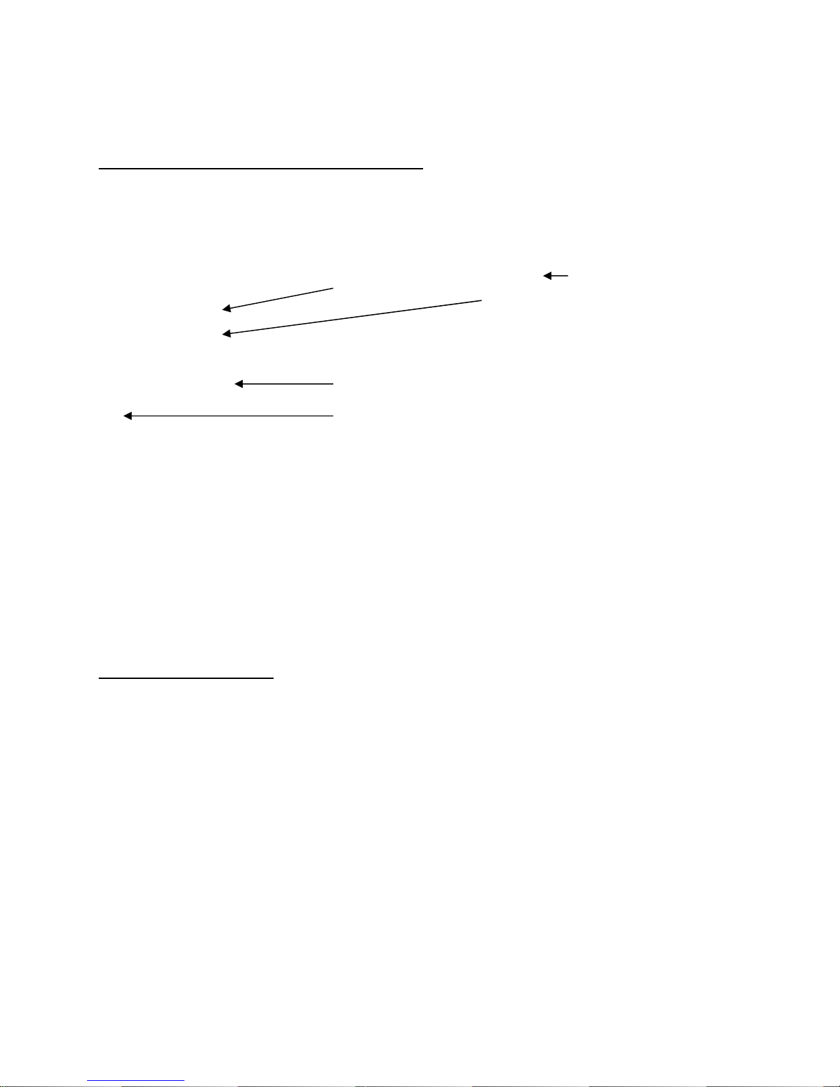
3.1.4. Mini Indoor Passive infrared sensor
Learn button
RB4:
• Connected for
E6 panels.
• Unconnected
for E12 and
E45 panels.
Dipswitch
1. For E12 and E45 panels, make sure that there is no LINK connected to RB4. For E6
panels, make sure that the 2 RB4 Pins are connected.
2. Connect the battery. The Connector can only go one way.
3. Press the Learn Button and check that the LED of the sensor comes on and stay’s on
for 2 to 3 seconds after you release the button.
4. Press the learn button on the panel once and make sure the LED switches on and
stays on.
5. Press the Learn button on the sensor and hold for 3 sec.
6. The Control Panel Learn LED may switch off.
7. The Control Panel Learn LED should flash and then stop.
8. To program this device to a zone follow the steps in section 3.2 of this document.
Battery Connector
3.1.5. Mini Door Guard
1. Press the Panic Button and check that the LED of the sensor comes on and stay’s on
for 2 to 3 seconds after you release the button.
2. Press the learn button on the panel once and make sure the LED switches on and
stays on.
20
Page 21
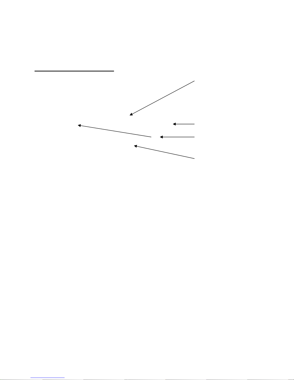
3. Press the Panic button on the sensor and hold for 3 sec.
4. The Control Panel Learn LED may switch off.
5. The Control Panel Learn LED should flash and then stop.
6. To program this device to zone follow the steps in section 3.2 of this document.
3.1.6. High power door guard
1. Open up the device and check that LK2 is configured correctly.
Check that the battery is connected.
2. Reassemble the unit and Press the Panic Button. Check that the LED of the sensor
comes on and stays on for 2 to 3 seconds after you release the button.
3. Press the learn button on the panel once and make sure the LED switches on and
stays on.
4. Press the Panic button on the sensor and hold for 3 sec.
5. The Control Panel Learn LED may switch off.
6. The Control Panel Learn LED should flash and then stop.
7. To program this device to a zone follow the steps in section 3.2 of this document.
LK2:
• Connected for
E6 panels.
• Unconnected
for E12 and
E45 panels.
Dipswitch
Panic Button
(Back of board)
Battery connector
21
Page 22

p
3.1.7. High power Seismic sensor
LK2:
• Connected for
E6 panels.
• Unconnected
for E12 and
E45
anels.
Dipswitch
Panic Button
(Back of board)
Battery Connector
1. Open up the device and check that LK2 is configured correctly.
Check that the battery is connected.
2. Reassemble the unit and Press the Panic Button. Check that the LED of the sensor
comes on and stays on for 2 to 3 seconds after you release the button.
3. Press the learn button on the panel once and make sure the LED switches on and
stays on.
4. Press the Panic button on the sensor and hold for 3 sec.
5. The Control Panel Learn LED may switch off.
6. The Control Panel Learn LED should flash and then stop.
7. To program this device to a zone follow the steps in section 3.2 of this document.
22
Page 23

3.1.8. High power Dual tilt sensor
LK2:
• Connected for E6
panels.
• Unconnected for
E12 and E45
panels.
Dipswitch
Panic Button
(Back of board)
Battery Connector
1. Open up the device and check that LK2 is configured correctly.
Check that the battery is connected.
2. Reassemble the unit and Press the Panic Button. Check that the LED of the sensor
comes on and stays on for 2 to 3 seconds after you release the button.
3. Press the learn button on the panel once and make sure the LED switches on and
stays on.
4. Press the Panic button on the sensor and hold for 3 sec.
5. The Control Panel Learn LED may switch off.
6. The Control Panel Learn LED should flash and then stop.
7. To program this device to a zone follow the steps in section 3.2 of this document.
23
Page 24

3.2. Associating Wireless Sensors with zones
Before installing a wireless sensor, the sensor should first be associated with the zone it
must be installed in.
1. Switch the E12 to Off Mode.
2. Enter the 6 digit master code, press the program button followed by enter. The
program button will light up, showing that the E12 is ready to be programmed.
3. Press the trouble button, followed by 2nd function, followed by enter. The program
button light and the trouble button light will switch on. All zone numbers which
already has one or two sensors associated will also light up.
4. Press the Learn button on the sensor.
5. All zone numbers with less than 2 sensors programmed in will start to flash. If a
button doesn’t flash, that corresponding zone has 2 sensors programmed in
already (Only 2 sensors per zone are allowed).
6. Press the required zone number button (Only flashing buttons). All buttons will
stop flashing and the zone numbers with sensors programmed in will stay on.
The sensor is now associated with that zone.
7. To program more sensors, start from step 4 above.
8. Press the enter button to exit program mode, when finished.
3.3. Removing Wireless Sensors from zones
Wireless sensors can be removed from a zone by following this procedure.
1. Switch the E12 to Off Mode.
2. Enter the 6 digit master code, press the program button followed by enter. The
program button will light up, showing that the E12 is ready to be programmed.
3. Press the trouble button, followed by 2nd function, followed by enter. The program
button light and the trouble button light will switch on. All zone numbers which
already has one or two sensors associated will also light up.
4. Press the zone number button that must be removed (Only switched on buttons).
The button will switch off when it is pressed and the sensor is now removed from
that zone. If there were 2 devices on that zone both will be removed.
5. To remove more sensors, repeat step 4 above.
6. Press the enter button to exit program mode, when finished.
3.4. Associating Key rings with Users
Each key ring remote must be programmed into the E12 before it can be used. Every
remote must be programmed in on a different number, 1-12 (for user 1- 12). The keypad
can be used to program in key ring remote controls by following this procedure:
1. Switch the E12 to Off Mode.
2. Enter the 6 digit master code, press the program button followed by enter. The
program button will light up, showing that the E12 is ready to be programmed.
24
Page 25

3. Press the trouble button followed by enter. The Program button light will switch
off and the trouble button light will switch on. The numbers already associated
with a remote will also switch on and can not be used again.
4. Press the yellow button on the key ring remote.
5. If it’s the first remote to be programmed in, the ‘1’ button will flash, indicating an
available space. The flashing button indicates the next available number. Select
the flashing number or any number with a button light which is off.
6. Press the selected button. The button light will switch on and stay on.
7. To program in more remotes, start from step 4 above.
8. When finished, press the enter button to exit program mode.
3.5. Removing Key rings
Key ring remotes can be removed from a zone by following this procedure.
1. Switch the E12 to Off Mode.
2. Enter the 6 digit master code, press the program button followed by enter. The
program button will light up, showing that the E12 is ready to be programmed.
3. Press the trouble button followed by enter. The Program button light will switch
off and the trouble button light will switch on. The numbers already associated
with a remote will also switch on.
4. Press the key ring number button that must be removed (Only switched on
buttons). The button will switch off when it is pressed and the key ring is now
removed from that user.
5. To remove more remotes, repeat step 4 above.
6. When finished, press the enter button to exit program mode.
3.6. Programming Active Zones
The keypad can be used to program active zones for all the different modes.
3.7. Programming Active Zones
The keypad can be used to program active zones for all the different modes.
Programming by keypad will only work for the partition with which the keypad is
associated.
3.7.1. Programming active zones for Away Mode:
Wired Zones:
• Switch the E12 to Off Mode.
• Enter the 6 digit master code, press the program button followed by enter. The
program button will light up, showing that the E12 is ready to be programmed.
• To program wired zones, press the Away button, followed by enter. The Away
button will light up and all the active zones will light up. If no zone buttons light
up, no wired zones are active in Away Mode.
25
Page 26

• To program a wired zone to be active in Away Mode, press the corresponding
zone number button on the keypad. The button will light up, indicating that the
zone will be active in Away Mode.
• To deactivate a zone, press the corresponding zone number button on the
keypad. The button light will switch off, indicating that the zone will not be active
in Away Mode.
• When all the zones have been programmed, simply press enter to return to
program mode.
Wireless zones:
• Switch the E12 to Off Mode.
• Enter the 6 digit master code, press the program button followed by enter. The
program button will light up, showing that the E12 is ready to be programmed.
• To program wireless zones, press the Away button, followed by 2nd function
followed by enter. The Away and Prog button will light up and all the active
wireless zones will light up. If no zone buttons light up, no wireless zones are
active in Away Mode.
• To program a wireless zone to be active in Away Mode, press the corresponding
zone number button on the keypad. The button will light up, indicating that the
zone will be active in Away Mode.
• To deactivate a zone, press the corresponding zone number button on the
keypad. The button light will switch off, indicating that the zone will not be active
in Away Mode.
• When all the zones have been programmed, simply press enter to return to
program mode.
3.7.2. Programming active zones for Stay Mode
Wired Zones:
• Switch the E12 to Off Mode.
• Enter the 6 digit master code, press the program button followed by enter. The
program button will light up, showing that the E12 is ready to be programmed.
• To program wired zones, press the Stay button, followed by enter. The Stay
button will light up and all the active zones will light up. If no zone buttons light
up, no wired zones are active in Stay Mode.
• To program a wired zone to be active in Stay Mode, press the corresponding
zone number button on the keypad. The button will light up, indicating that the
zone will be active in Stay Mode.
• To deactivate a zone, press the corresponding zone number button on the
keypad. The button light will switch off, indicating that the zone will not be active
in Stay Mode.
• When all the zones have been programmed, simply press enter to return to
program mode.
Wireless zones:
• Switch the E12 to Off Mode.
26
Page 27

• Enter the 6 digit master code, press the program button followed by enter. The
program button will light up, showing that the E12 is ready to be programmed.
nd
• To program wireless zones, press the Stay button, followed by 2
function
followed by enter. The Stay and Prog button will light up and all the active
wireless zones will light up. If no zone buttons light up, no wireless zones are
active in Away Mode.
• To program a wireless zone to be active in Stay Mode, press the corresponding
zone number button on the keypad. The button will light up, indicating that the
zone will be active in Stay Mode.
• To deactivate a zone, press the corresponding zone number button on the
keypad. The button light will switch off, indicating that the zone will not be active
in Stay Mode.
• When all the zones have been programmed, simply press enter to return to
program mode.
3.7.3. Programming active zones for Monitor Mode
Wired Zones:
• Switch the E12 to Off Mode.
• Enter the 6 digit master code, press the program button followed by enter. The
program button will light up, showing that the E12 is ready to be programmed.
• To program wired zones, press the Monitor button, followed by enter. The
Monitor button will light up and all the active zones will light up. If no zone buttons
light up, no wired zones are active in Monitor Mode.
• To program a wired zone to be active in Monitor Mode, press the corresponding
zone number button on the keypad. The button will light up, indicating that the
zone will be active in Monitor Mode.
• To deactivate a zone, press the corresponding zone number button on the
keypad. The button light will switch off, indicating that the zone will not be active
in Monitor Mode.
• When all the zones have been programmed, simply press enter to return to
program mode.
Wireless zones:
• Switch the E12 to Off Mode.
• Enter the 6 digit master code, press the program button followed by enter. The
program button will light up, showing that the E12 is ready to be programmed.
• To program wireless zones, press the Monitor button, followed by 2nd function
followed by enter. The Monitor and Prog button will light up and all the active
wireless zones will light up. If no zone buttons light up, no wireless zones are
active in Monitor Mode.
• To program a wireless zone to be active in Monitor Mode, press the
corresponding zone number button on the keypad. The button will light up,
indicating that the zone will be active in Monitor Mode.
• To deactivate a zone, press the corresponding zone number button on the
keypad. The button light will switch off, indicating that the zone will not be active
in Monitor Mode.
27
Page 28

• When all the zones have been programmed, simply press enter to return to
program mode.
3.8 Programming Passwords
The keypad can be used to program user passwords (Default: 1234) and the Master
password (Default: 123456):
Programming User Passwords:
1. Switch the E12 to Off Mode.
2. Enter the 6 digit master code, press the program button followed by enter. The
program button will light up, showing that the E12 is ready to be programmed.
3. Press the MEM button followed by the user number (1-12). Pressing 2, for
example, will mean that user password 2 must be programmed in. The selected
number button will start to flash.
4. Enter the 4 digit numeric password and press enter.
5. To program the next password start from step 3 above. All 12 user passwords
are programmed in the same way.
Programming the Master Password:
1. Switch the E12 to Off Mode.
2. Enter the 6 digit master code, press the program button followed by enter. The
program button will light up, showing that the E12 is ready to be programmed.
3. Press the MEM button followed, by 2nd function, followed by enter. The MEM
button will start to flash.
4. Enter the 6 digit numeric password and press enter.
5. Press enter a second time to exit program mode.
28
Page 29

4. Summary of SMS Commands
In the table below, XXXX is a four digit user password.
Modes and Functions
Description Command Explanation or Default SMS
Switch to Away Mode $XXXXA Away Mode Group A/Group B
Switch to Stay Mode $XXXXS Stay Mode Group A/Group B
Switch to Off Mode $XXXXO System Off Mode Group A/Group B
Switch to Monitor Mode $XXXXM Monitor Mode Group A/Group B
Silent Panic $XXXXH Silent Panic Group A/Group B
Panic $XXXXP Panic Group A/Group B
Reset E12 $XXXXr Reset Group A/Group B
Trigger Gas discharge $XXXXG9 Gas Triggered
Switch Output 1 On $XXXXB1 Output 1 On
Switch Output 1 Off $XXXXB0 Output 1 Off
Pulse Output 1 $XXXXB9 Output 1 pulse (Switch On and Off)
Switch Output 2 On $XXXXC1 Output 1 On
Switch Output 2 Off $XXXXC0 Output 1 Off
Pulse Output 2 $XXXXC9 Output 1 pulse (Switch On and Off)
Switch Output 3 On $XXXXD1 Output 1 On
Switch Output 3 Off $XXXXD0 Output 1 Off
Pulse Output 3 $XXXXD9 Output 1 pulse (Switch On and Off)
Switch Output 4 On $XXXXE1 Output 1 On
Switch Output 4 Off $XXXXE0 Output 1 Off
Pulse Output 4 $XXXXE9 Output 1 pulse (Switch On and Off)
Enable/Disable functions + Information requests
Enable Gas discharge $XXXXG1 Auto Gas Enabled
Disable Gas discharge $XXXXG0 Auto Gas Disabled
Disable 24 hr test signal $XXXXV Disable 24 H
Enable Seismic detector $XXXXp Seismic Detector On
Disable Seismic detector $XXXXq Seismic detector Off
Request signal strength $XXXXT /31 Signal Strength
Request alarm panel time $XXXXt Unit will reply with its current time and date setting
Request Timer Settings $XXXX* All timer settings will be sent to the requesting Cell
phone
Request Base and SMSC numbers $XXXXI Base station and SMSC numbers will be given
Request Cell numbers $XXXXJ All 4 programmed cell numbers will be given
Status request $XXXXL Status of alarm/Mains power/Battery
Request zone setup $XXXXs Reports the zone setup for the different modes
Set Outputs as Telemetry outputs $XXXX) See Section 1.5
Set Outputs as SMS outputs $XXXX( See Section 1.5
Disable SMS sending in Monitor- +
Stay mode
Enable SMS sending in Monitor- +
Stay mode
Table 3.
Summary of SMS Commands.
$XXXX> No SMS’s will be sent when panel is in monitor or
stay mode
$XXXX< All SMS’s will be sent when panel is in monitor or
stay mode
29
Page 30

Appendix A: Wiring Diagram
Figure 9.
Wiring diagram for the E12 Cleo.
A.1
Page 31

Appendix B: Connecting multiple keypads to the E12
Figure B.1.
E12 Cleo PC board, showing the location of the keypad connectors and keypad
terminating pins.
Keypad Terminator
pins
Figure B.2
E12 keypad PC board, showing the location of the keypad terminating pins.
B.1
31
Page 32
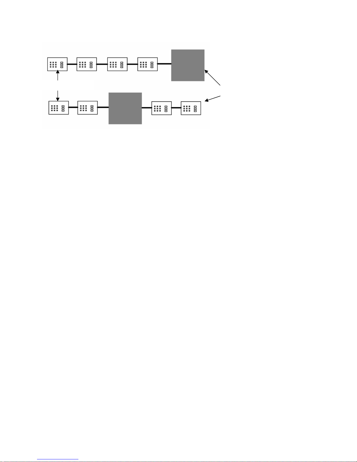
Pins Connected
Pins Connected
Figure B.3
Keypads connected to panel.
Two keypads can directly connect to the panel, using the connectors shown. To connect
more than 2 keypads to the panel, the keypads must be wired in parallel. The keypad
terminator pins must be connected for the two devices on the opposite edges of the
connection and unconnected for the other devices. Figures B.1 and B.2 shows the
location of the keypad terminating pins on the panel and keypad respectively. Figure
B.3 shows 4 keypads connected to a panel in two different formats. The keypad
terminating pins must be connected as shown in figure B.3.
B.2
32
Page 33
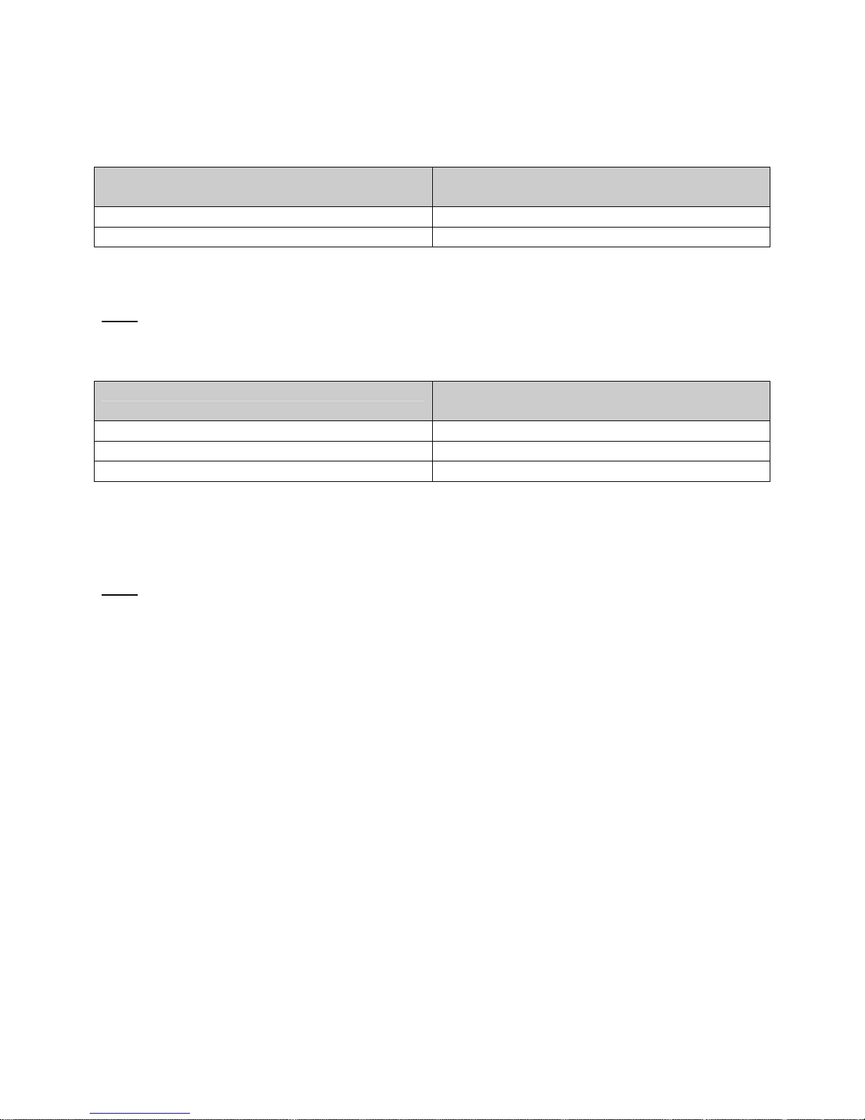
Appendix C: Dipswitch settings for E6 devices
Settings used with E6 PIR
Function Dipswitch setting
1 2 3 4
Learn 0 0 0 1
Trigger 1 0 0 1
Use the Learn function setting to learn the device into the panel. After successfully
reading in the device, the dipswitch must be set to the trigger function.
Note: To Learn the device in, press the learn button or use TX shunt on older PIR's
Settings used with E6 Door Guard
Function Dipswitch setting
1 2 3 4
Learn 1 0 0 1
Trigger in away mode 0 1 0 1
Silent in any mode 0 0 1 1
Use the Learn function setting to learn the device into the panel.
Trigger in away mode: Will cause an alarm condition if triggered while the panel is in
away mode.
Silent in any mode: Trigger notification via telemetry outputs and keypad only.
Note: To Learn the device in use the NC or NO input, DO NOT USE THE PANIC BUTTON!!
WHEN USING E6 DEVICES, NO TAMPER AND PANIC FUNCTIONS ARE
AVAILIBLE! IF THESE FUNCTIONS ARE REQUIRED, USE E12 / E45 DEVICES.
33
Page 34
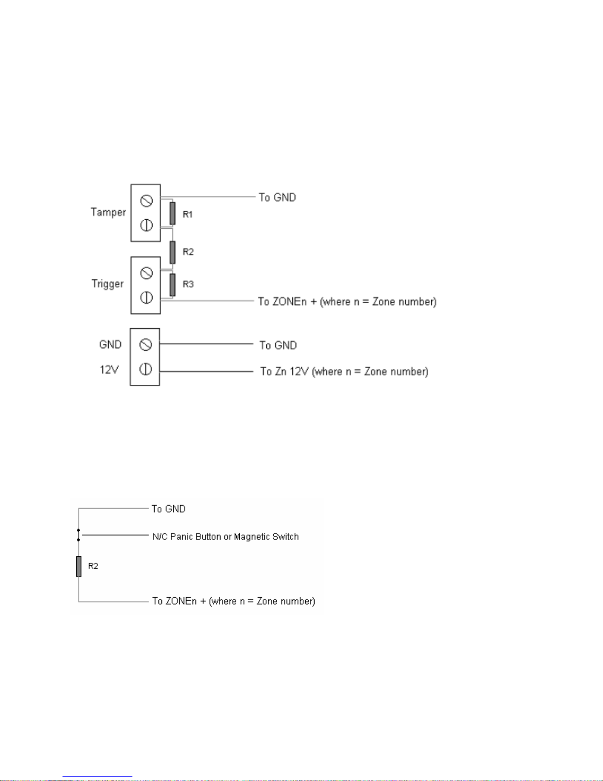
Resistor Values
R1 = 1K8 Ohm
R2 = 470 Ohm
R3 = 7K5 Ohm
Figure 10.
A.1
Connecting a passive infrared sensor to the E12. Also see figure 9 for wiring on
the panel’s side.
Figure 11.
Connecting a Normally Closed panic button or magnetic switch to the E12 for 24
hour monitoring (Opening the switch will result in a notification message only, no
alarm condition). Zone n must be active in Away mode. Also see figure 9 for
wiring on the panel’s side.
34
Page 35
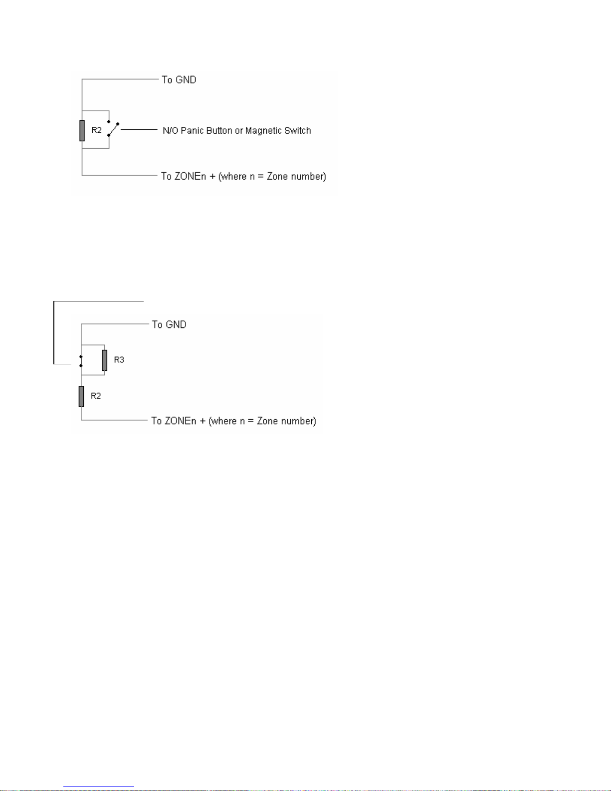
Figure 12.
Connecting a Normally Open panic button or magnetic switch to the E12 for 24
hour monitoring (Closing the switch will result in a notification message only, no
alarm condition). Zone n must be active in Away mode. Also see figure 9 for
wiring on the panel’s side.
N/C Magnetic Switch
Figure 13.
Connecting a Magnetic Switch to the E12 for normally closed operation (Opening
the switch will cause the alarm to trigger, only if the alarm is armed). Also see
figure 9 for wiring on the panel’s side.
35
Page 36

Figure C.4
Garrison Beam connection to the E12 Cleo.
A.3
36
 Loading...