

Page 1

LED 2612 QD
66cm(26")
66cm (26") LED TV
Page 2

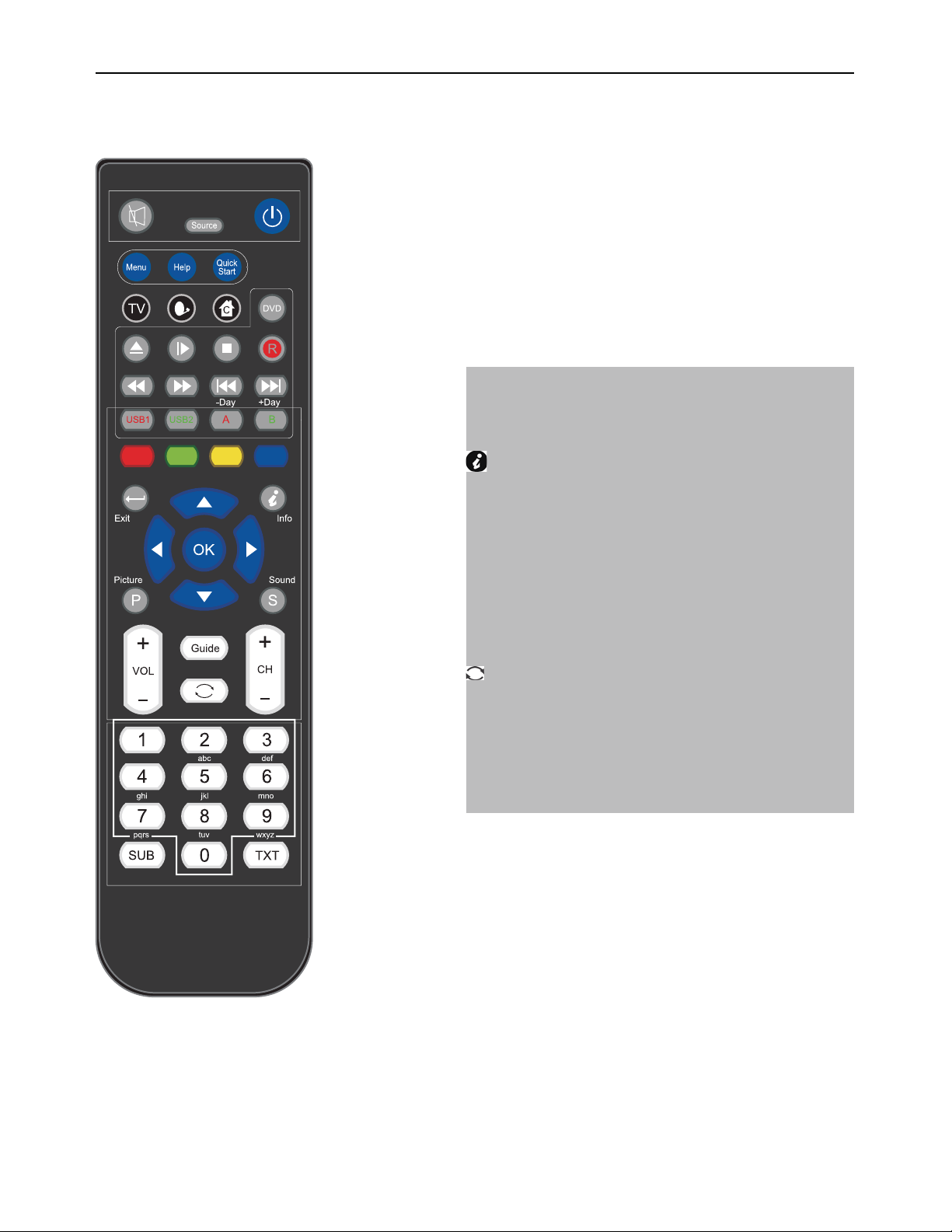
Remote control instructions in DTV/USB mode
Mute
Unmute sound Available in all modes.
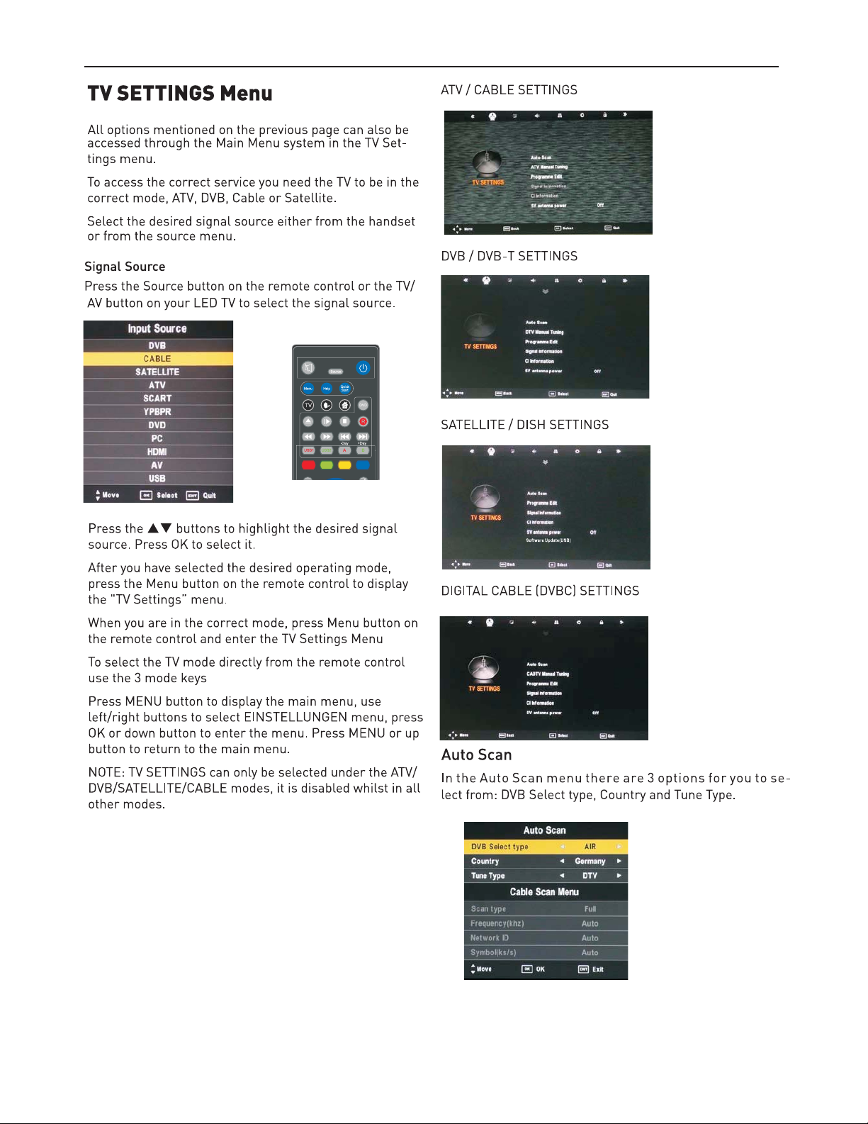
SOURCE
Display / Hide Source Menu.
Power button
On/Off Standby mode.
Menu
Display / Hide main menu, step back one menu, exit menu.
Help
Display / Hide the Help Menu.
Quick start
Display / Hide the Quick start menu.
Short cut to ATV source. Sequences ATV, DVBT-TV, DVBTRadio, ATV
Shortcut to DVBS/DVBS2 source.
Shortcut to DVBC source
(Timeshift)*
Play or pause.
Press to enter Timeshift, the image paused and it start
record from the paused position.
EN
Stop playing or stop recording.
Fast reverse and Fast forward.
Previous / next chapter in USB mode or play the Previous
/next scene of the recorded programs, jump by 30 seconds.
VOL+/VOL-
Press to increase / decrease the sound level.
CH+/CH-
When watching a channel, changes the channel.
NUMBER BUTTONS
Press 0-9 to select a TV channel directly when you are
watching TV. The channel change after 2 seconds.
* depending on the model
Page 3
Remote control instructions in TELETEXT mode
Coloured
Fast text when in update mode and fast text links present.
Can be used for other functions in Hold mode.
Exit
Exit text mode.
(Index)
Index page (page 100)
Up/Down
Select +/- Page in Hold mode.
Left / Right
Hold main page and select sub pages using Red / Green
soft.
OK
Hold page and Expand TOP / Bottom / Full , Use TXT for
Update.
NUMBER BUTTONS
Press 0-9 to select a teletext page.
Press this button to show hidden text (e.g. the solutions for
TV quiz shows). Press it again to hide the text.
SUB
Subtitle display/ select button (can display/Hide a menu).
TXT
Text / Mix / TV( always in Update mode)
Page 4
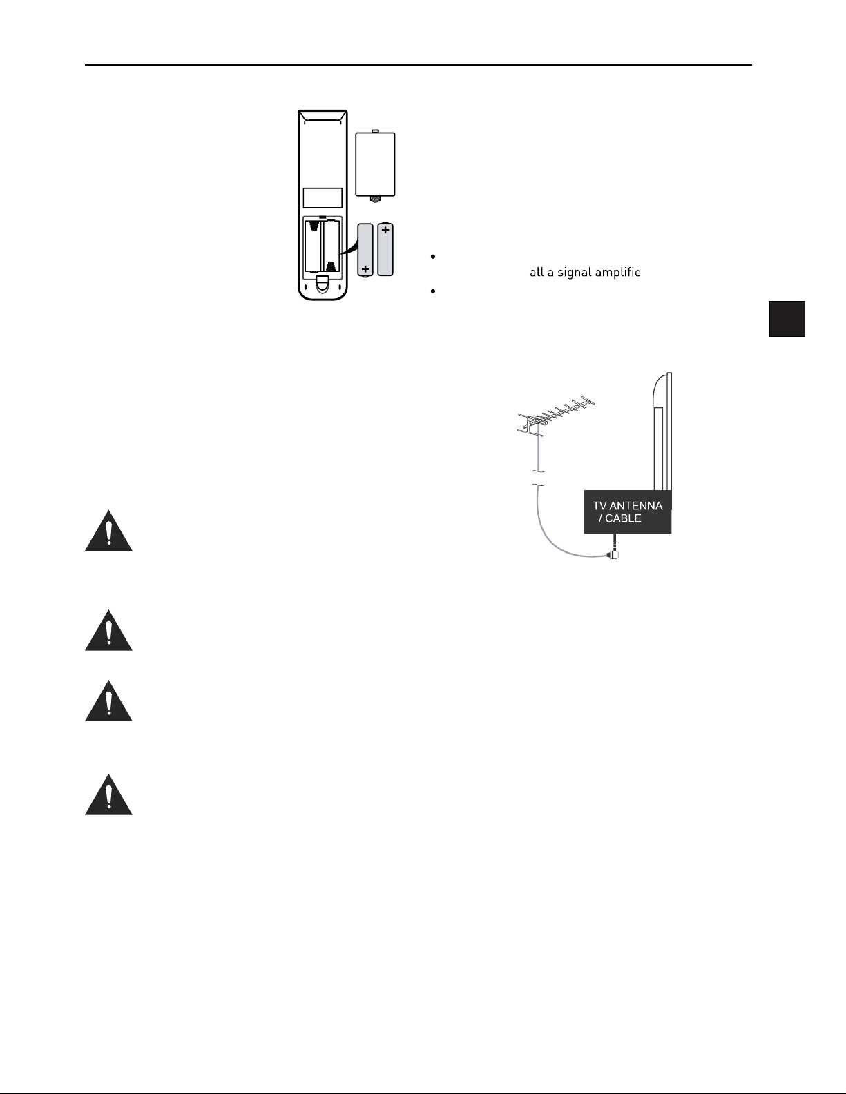
Installing Batteries in the
Remote Control
1. Remove the battery compartment cover at the rear of the
remote control by pushing
the retaining clip forward and
pulling up.
2. Install the supplied batteries, ensuring the polarity
matches what is shown in the
battery compartment.
3. Replace the battery compartment cover.
Using the Remote Control
To use the remote control point it at the TV and press the
required buttons. You must be within 6 meters and at an
angle of less than 30 degrees from the center of the TV.
NOTE: Sunshine or other strong light sources may interfere with the signal from the remote control. In this situation turn the TV away from the light source.
WARNING! DO NOT LEAVE BATTERIES IN
THE REMOTE CONTROL FOR EXTENDED
PERIODS AS THEY CAN LEAK OR CORRODE
CAUSING DAMAGE TO THE REMOTE CONTROL. CHECK THEM PERIODICALLY AND
REPLACE THEM AS REQUIRED.
WARNING! DO NOT MIX BATTERY TYPES.
WHEN INSERTING BATTERIES, REPLACE
ALL BATTERIES AT THE SAME TIME. DO
NOT MIX OLD AND NEW BATTERIES.
WARNING! EXHAUSTED BATTERIES MUST
BE TREATED WITH CARE AND DISPOSED
OF ACCORDING TO ANY SAFETY OR RECYCLING REGULATIONS IN FORCE IN YOUR
LOCAL AREA, NEVER DISPOSE OF BATTERIES INTO GENERAL WASTE, OR FIRE.
WARNING! NEVER EXPOSE BATTERIES TO
EXCESSIVE HEAT SUCH AS SUNSHINE, FIRE
OR THE LIKE.
Aerial connection
WARNING! ENSURE THE TV AND ALL ANCILLARY
EQUIPMENT IS UNPLUGGED FROM THE MAINS BEFORE
MAKING ANY CONNECTIONS!
Connecting the TV Antenna
Connect the TV antenna to the aerial socket with a 75
ohm co-axial plug. For best results use a high gain TV
aerial, preferably roof or loft mounted.
To improve picture quality in a poor signal area, purchase and inst
If the antenna needs to be split for two TVs, use a 2Way Signal Splitter (not supplied).
r.
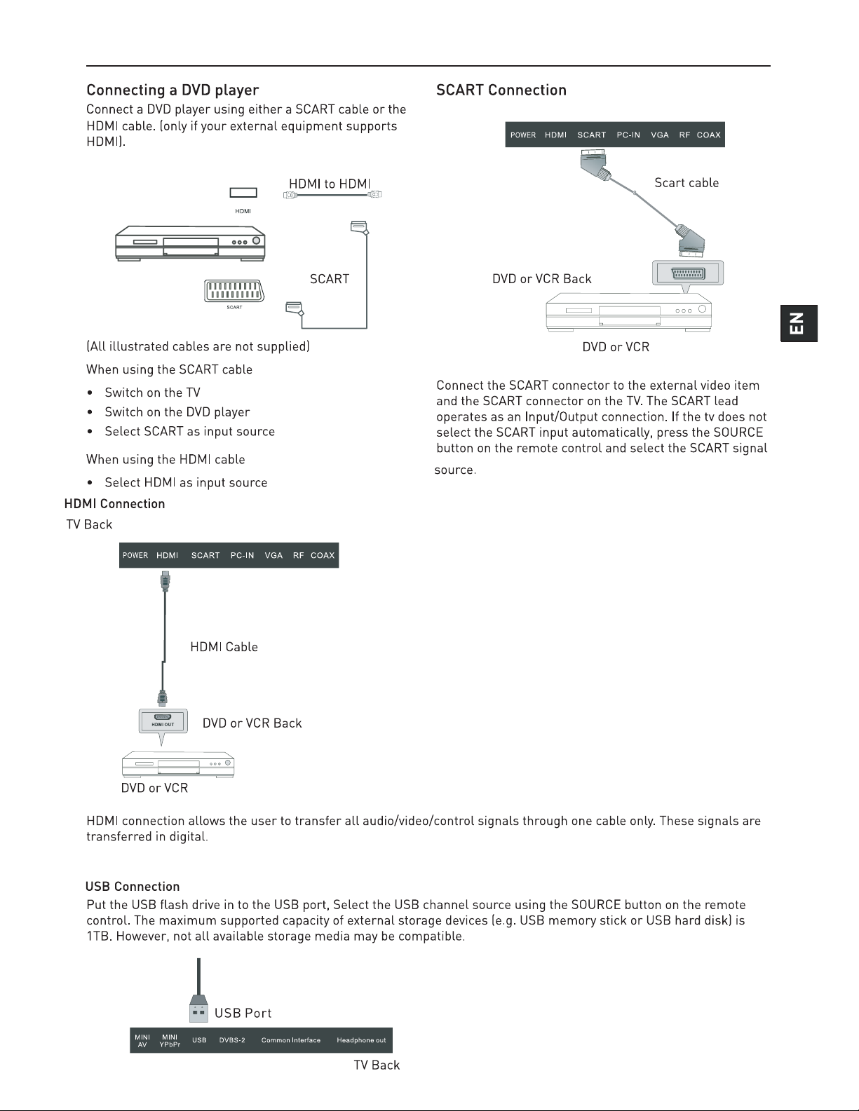
Connecting external devices
This instruction manual shows the simplest and most effective way of connecting your TV to ancillary equipment.
Alternate methods are listed below.
HDMI Lead
You can connect this TV to a compatible device using a
HDMI lead. This method will give the best picture.
Connect the cable from the HDMI equipment to the TV
HDMI socket.
SCART Lead
You can connect this TV to a compatible device using
a SCART lead. The connection uses component video
signals, i.e. the red, green and blue (RGB) content of the
video are sent on separate signals.
EN
VGA Cable
You can use your TV as a monitor for your personal computer by using a VGA cable. Sound from your personal
computer may also be played through the TV.
Page 5
Connecting external devices
CONNECTIONS
Name Function Description
POWER Connect to power supply
HDMI
SAT LNB Connection
VGA (PC IN)
PC-IN PC Audio input
Mini YpbPr
Mini AV
SCART
RF Connect to TV signal cable
Head phone Connect Head phone
CI / CI+ CI slot (Pay as you view card slot)
Coax Output t
USB Media playback
Connect to the HDMI output of your
DVD or Satellite Box
Connect to Satellite signal
Connect to the PC VGA output to display PC graphics
Connect to the YPbPr output on external devices
Connect to AV output on external
devices
Connect to the SCART input / output
of external devices
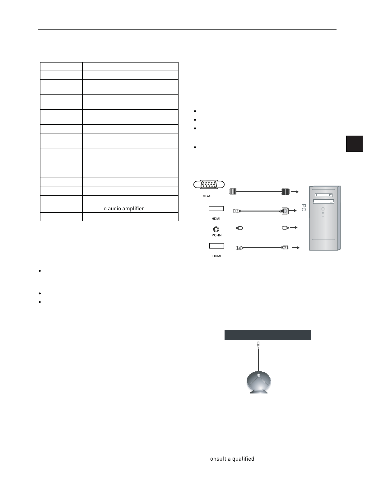
VGA, HDMI PC Connection
Use a PC-VGA cable (not supplied) to connect the TV to
your PC. You can also use an HDMI cable to connect to
your PC (if your PC Graphic card supports HDMI). When
the HDMI cable is used, the PC audio cable is no longer
required. If you use the HDMI to DVI cable, you will need
to use the PC audio cable. Connect all cables carefully
and do not bend or break the connector pins.
When using the VGA cable
Switch on the TV
Switch on the PC
Select PC/VGA as input source
When using the HDMI cable
Select HDMI as input source
VGA cable
HDMI to DVI cable
Audio cable
EN
Caution:
Before connecting external devices:
Makes sure to disconnect the appliances from the
power supply in order to avoid any potential damage
from occurring.
Make sure to establish the required connection.
Make sure that the connectors are properly and cor
rectly attached before connecting the appliances to the
power supply.
PC connection
As PCs are sometimes still supplied with a ‘conventional’
CRT monitor, you may need to adjust the display settings of your PCs graphics card, otherwise the pictures
may not appear correctly. Switch on your PC (still with
your original monitor connected) now select the screen
resolution, and select 60Hz refresh rate. Switch o your
PC, then connect it to your TV while both appliances are
still switched o.
HDMI to HDMI
(All illustrated cables are not supplied)
-
Satellite connection
INI
INI
USB DVBS-2 Common Interfa ce Headphone out
P P
V
DVB-S/DVB-S2 Signal
Connect the DVB-S/DVB-S2 signal to the SATELLITE LNB
on the TV SET. Select the SATELLITE input source using
the DVBS/DVBS2 button on the remote control.
Note: If there is no DVBS(S2) reception, please check
whether there is any problem (such as a short-circuit) on
the F-type connector, on the LNB cable, the multi-switch
etc. of your satellite antenna system. In this case, please
disconnect the TV set from the antenna system. If necessary, c
technician to solve the problem.
Page 6
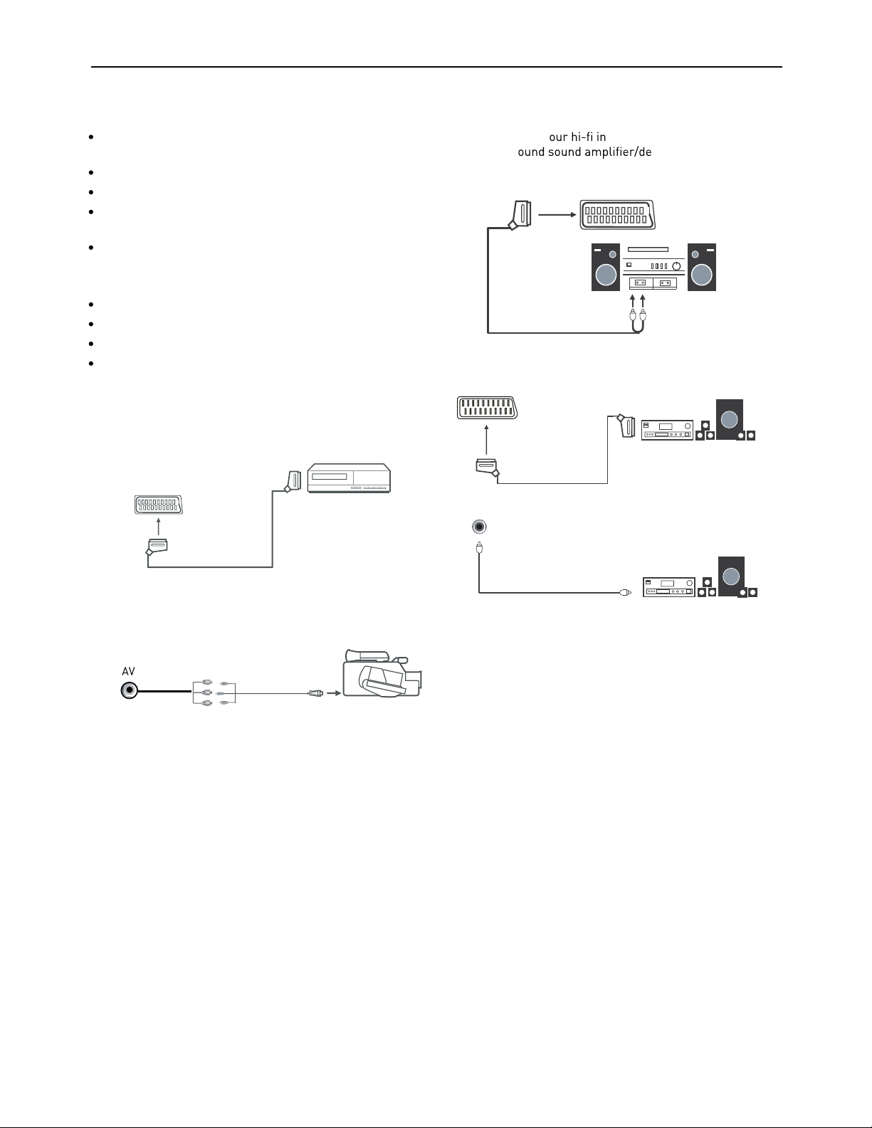
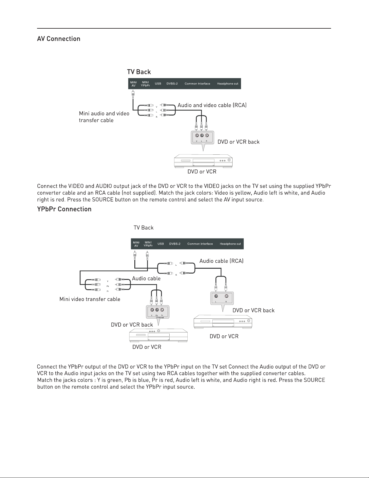
Connecting Video camera and Video recorder
Video camera
Connect the AV cable to the TV and to the video camera.
Turn on both video camera and the TV.
Select AV/CVBS source
You can now see the playback picture from the video
camera. Note:
To connect the video camera using other cables, refer
to the video camera instruction manual.
Video recorder
Connect the Scart cable to the TV and video recorder.
Turn on both video recorder and the TV.
Select Scart source
You can now see the playback picture from the video
recorder.
Note:
To connect the video recorder using other cables, refer to
the video recorder instruction manual.
Connecting an audio system
You can supply the TV sound to the stereo system (A) with
the Scart socket. Use a special Scart cable SCART to RCA.
(Please consult y
have a surr
Scart cable or the special Scart cable Scart to RCA.
Scart to RCA cable
structions for details). If you
coder (B) Use the
Scart cable
Mini Audio and Video transfer
cable
(Mini AV cables are supplied)
Video recorder
Video camera
Scart cabl
Coax cable
(All illustrated cables are not supplied)
e
Page 7
Page 8
Page 9
CommonInterfaceSlot
Auto installation setup
USING YOUR COMMON INTERFACE SLOT
This TV set features a CI+ slot and supports the following
digital standards:DVB-T, DVB-S(S2) and DVB-C.
Common Interface
The Common Interface (CI+) slot is designed to accept
the Conditional Access Module (CAM) and Smart Card
in order to view the pay TV programmes and additional
services. Contact your Pay Per View TV service provider
to get more information about the modules and subscriptions
NOTE: Conditional Access Module and Smart Cards are
sold separately
WARNING! SWITCH OFF YOUR TV BEFORE ANY MODULE
IS INSERTED INTO THE COMMON INTERFACE SLOT,
THEN ADD THE SMART CARD TO THE CAM
CI+Slot
CAM
SmartCard
1 Turn on the TV and ensure ‘DTV’ Source is selected
2 If the CAM is detected the TV will display the following
message on the screen. “Common Interface Module
inserted “wait for a few moments until the card is
activated
3 Select the relevant digital Pay Per View channel
4 Detailed information on the Smart Card in use is dis-
played
5 Press the Ok button to access the card menu. Refer to
the Module Instruction Manual for setting details
6 When the module is removed, the following message
will appear on the screen. “Common Interface module
removed“.
Power On / Off the LED TV
To turn on the LED TV
Press the power button on the LED TV or the POWER button on the remote control, the standby indicator will light
green
To turn off the LED TV
Press the power button on the LED TV or the POWER button on the remote control, the standby indicator will light
red
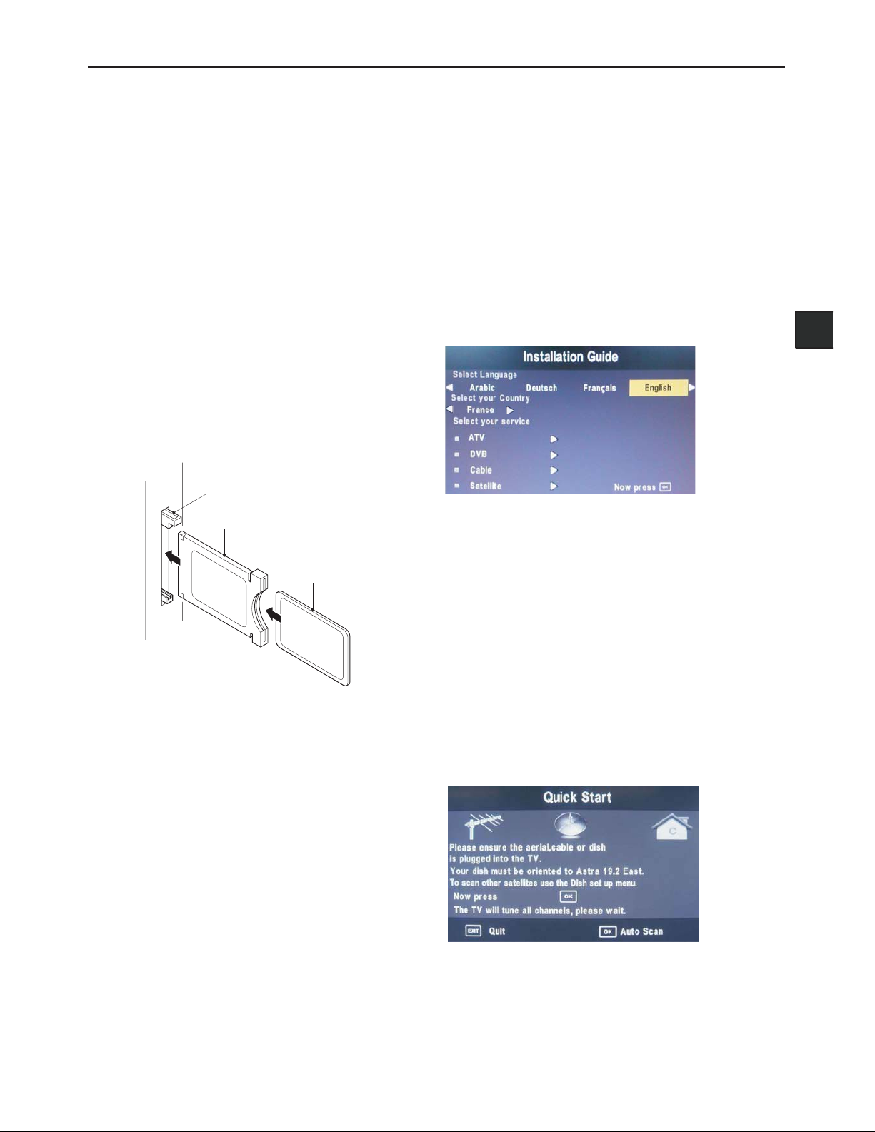
When you initially turn on the LED TV you will see the fi rst
timeinstallationmenuasbelow
Use the left/Right/Down keys to select your language
and country use the up/down keys to select the type of
service you want to install. You can only install one service
at a time but you can return to this menu in order to install
an additional service by pressing the Quick Start button.
ATV (Analogue Television) is used for Analogue Cable
systems
DVB (DTT - Digital Terrestrial Television, DVB-T) is used if
you have an antenna receiving signals from a terrestrial
transmitter
Cable is used for Digital Cable sy
Satellite dex if a deen uoY .E2.91 artsA
with a univ
the full satellite installation menu
Press OK button and you will see the following menu.
Ensure your aerial, cable or dish is plugged in to the TV
and then press OK again
The TV will start to install the service you have selected
This could take some time depending on your selected
service
Select Home mode and confirm with OK button.
You can tune an additional service at any time by pressing
the Quick Start button.
ersal LNB. To install any other satellites use
rofteserp si dish
stems (DVBC)
EN
Page 10
Page 11
Press
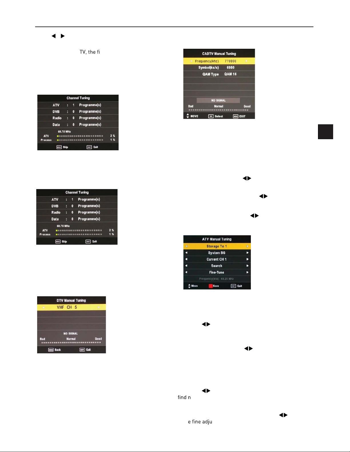
Type, press OK to start scanning.
If you select ATV+D
for ATV tuning, while the second 50% represent DTV tuning. When ATV tuning, you can press MENU to Skip ATV
tuning and start DTV tuning or press EXIT to exit tuning.
During the channel search a preview of the already-found
channels is displayed.
/ to select DVB Select type, Country and Tune
rst 50% of the processing is
CADTV (DVB-C) Manual Tuning
Unlike QUICKSTART the satellite search will search the
whole satellite for channels and will not be instant.
Also the channels will appear in the order on the satellite
and not the pre-set order.
Auto search replaces any previous searched channels
with those of the new search. To add an extra satellite if
you have a suitable Dish/LNB/Switch you must use the
Dish Installation menu.
TV (DVBT) Manual Tuning
D
You can manually tune CADTV channels in the TV SETTINGS menu.
Note: for more information about the channel parameters
(frequency, symbol rate and QAM type), please check with
your cable TV provider.
Frequency
Select Frequency using the buttons.
Symbol (ks/s)
Select the Symbol (ks/s) using the buttons.
QAM Type
Select the QAM Type using the buttons
ATV (analogue cable TV) Manual Tuning
EN
You can manually tune DTV channels in the TV SETTINGS
menu. Press the Left/Right arrow buttons to select the
channel you wish to tune, then press OK button to scan
for the channel.
You can manually tune ATV channels in the TV SETTINGS
menu.
Storage to
Press the buttons to change the numbered location
of the found channel.
System
Select the system using the buttons.
Current CH
Displays the current channel number, press the buttons
to choose the channel you wish to modify.
Search
Press the buttons to scan through the frequencies to
ew channels.
Fine tune
In case of bad reception, you can press the buttons to
mak
ing is complete, please press the RED button to save any
found channels.
stments to the tuning. After manual tun-
Page 12

PROGRAMME EDIT
navigate through the menu
Delete
Press the RED button to delete the highlighted channel, a
Move
Press to select the channel, press yellow button to
enter the move mode, then press
to move the chan-
Cl Information
-
channels is not possible.
5V antenna power
Press button to turn on or off.
Software Update (USB)
1. Download the software to the usb device, then insert the
usb device to the unit.
2. Press the Menu button to select the TV SETTINGS menu.
3. Press the buttons to select Software Update(USB) and
then press the OK button to update software .
4. when the updating is completed, the unit will be reset to
standby mode.
Power-Off-No-Signal-Down
If no valid input signal is detected, the TV set will toggle to
Auto-Power-Down
the last channel switching, the TV set will automatically
toggle from On to standby mode. Prior to this automatic
toggling, a message will be displayed allowing you to
Guide (EPG – Electronic Program Guide)
Skip
Press to select the channel you wish to skip.
channel name and the channel will be skipped when you
scroll through the channels.
main menu.
Rename (Only available in ATV)
Modify current channel name.
Press the
the
button to enter RENAME mode, then use
buttons to change name. Press the green
Favorite
Press the green button to set the favorite channel.
Signal Information
channel /network/modulation/quality /strength.
the Electronic Program Guide. EPG contains a 7-day
programme preview as long as the selected channel
supports this function. If there is more information about
a programme, press the and buttons to scroll
-
able number of characters is limited.
Favourite Lists
ton to add it to the list of favourite channels. To remove a
channel from the favourite list, select the desired channel
create an own favourite list for each tuner module.
Dish Setup
section.
or with a different LNB you will need to use this section.
3. If you have a motorised Dish with a DiSEqC rotator
and wish t
this section.
4. If you are on a DiSEqC switch system you will need
this section.
o tune more than one satellite you will need
-
long as you know what satellite your dish is aligned with
Installation of 3 & 4 require an experienced user or
engineer.
Page 13

To set a different Satellite or LNB
Select Satellite mode, press MENU key, navigate down to
the Dish Setup option, press OK. You will see the Satellite
Dish Setup menu.
Satellite List
The Satellite list displays the satellite names.
To set Multiple Satellites and LNBs (only possible
on multi-LNB dish, switch systems)
Use buttons to select the satellite to which your dish
is aligned. Press OK. An arrow will display against the
chosen satellite.
Press
Select the LNB type and settings for your LNB.
Press the Exit button and the
ond satellite.
Use
keys to select the satellite to which your dish is aligned.
Press OK. An arrow will display against the chosen satellite.
Press
Select the LNB type and settings for your second LNB
and switch settings.
Press the Exit button and the
Press the blue Key twice to search the satellite channels.
A full description of the advanced Dish set up for
multiple satellites using DiSEqC switches and DiSEqC
positioner follows. This should only be attempted by
experience users.
The Dish set up main menu page displays the main interface. The interface consists of Satellite List, Transponder
list and Dish/LNB parameter list
button to navigate to LNB section of the menu.
button to select the sec-
buttons to select the second satellite. Use
button to navigate to LNB section of the menu.
button.
Satellite Edit
No. The current list number of the selected satellite Sat-
ellite name. The No. cannot be edited.
Satellite name: Press the green button to open the edit
menu explained below.
For editing via the on-screen keyboard, press the
ton.
In the input frame, use
characters.
Input Frame (On-screen keyboard)
Extend: Extended characters
Caps On: Change character case. Press OK button to
select.
Back: Delete letters, press OK to c
OK: Sure to set the naming of the satellite, and return to
Edit Menu
Cancel: Return directly back to edit menu.
Longitude Direction: Added to determine the location of
the satellite. Use the
East.
Longitude Angle: Input Longitude. By moving the cursor
tu buttons to enter the satellite longitude.
Band: band selection. Press
arrow buttons to select West/
and OK button to select
to select.
but-
EN
Page 14

Delete Satellite menu
Press the YELLOW button, the c -
r. Press OK to de ete.
Add Satellite
Press the RED button t
NO: s r c
ted.
Adjus
s re ress OK t ve or
ress EXIT o c c
A ne s t
t te.
r ter ccor to the
Edit Transponder menu
Press GREEN button to enter Tr
(khz)
No. s r. Nr. c -
ted
Frequency: Set the do
Symbol (ks/s):
Polarity:
Delete Transponder
Press the YELLOW button, the c -
r. Press OK to de ete.
requency.
te.
t v c
Transponder List
st sho r rs or the se ect t te.
Add Transponder
Press RED button to ent r
No. ted.
Frequency: Set the do
Symbol (ks/s):
Polarity:
requency.
te.
t v c
Page 15

Dish Parameter description
LNB Type: LNB Frequency
Highlight the LNB Type , and use the
to enter submenu then you c
buttons or Ok
rameters.
LNB Power: Polarization switching power supply, Press
to select On/Off.
On: Allowed to receive Horizontal / Vertical Polarization
program.
Off: out-off of supply.
22KHz: The level of the LO switch / DS switch ( Require
the user to have installed 22KHzSatellite signal switch).
Press
to select Auto/On/Off.
EN
Auto: Automatically issued 22 KHz pulse signal to control
switching.
On/Off: Manual control switch.
Tone burst: Double Single Switch (Require users to install
Tone burst switch), Press
B/None.
Burst A /Burst B: Manually switch the satellite A/B.
DiSEqC1.0: 4 select 1 switch ( Require the user device
support DiSEqC 1.0 protocol). Press
LNB2/ LNB3/LNB4/None.
LNB1/LNB2/LNB3/LNB4: Corresponding to a satellite ,
After selecting the corresponding list will appear in the
satellite list.
to select Burst A/Burst
to select LNB1/
Page 16

DiSEqC 1.1: 16 select 1 switch ( Require the user device
support DiSEqC1 .0 protocol) Equipment needs support
DiSEqC 1.1 protocol, Most control 16
LNB. Press to
select LNB1~LBN16/None.
LNB 1-LNB 16: Corresponding to a satellite, After selecting the corresponding list will appear in the satellite list.
Motor: Control of multi-satellite polar (Require the user
device support DiSEqC1.2 or DiSEqC1.3 protocol), Left
and right buttons to select DiSEqC1.2/ DiSEqC1.3/None.
DiSEqC1.2: DiSEqC1.2 Protocol selection
DiSEqC1.3: DiSEqC1.3 Protocol selection
For Mot
te “DiSEqC1.2“ , Operating Instructions:
Press RED button to enter “Set Limit" menu.
Press OK button to enter Set Position menu.
Move Continue: Control of the east or the west continued
to turn the polar axis to the desired position.
Move Step: Control of the east or wes
xed polar
axis step rotation.
Move Auto: East or west of Automatic Control continued
to turn the polar axis to the desired position.
Move Continue: Manual control of the east or the west
continued to turn the polar axis to the desired position.
Move Step: Control of the east or wes
xed polar
axis step rotation.
Store Position: Save the current rotation angle of polar
axis.
Goto Position: Control the polar angle automatically to
the previously saved.
Goto Reference: Control the angle of polar axis automatically to the default. When Mot
ress RED button to enter “Set Limit“ and Mot
P
te “DiSEqC1.3“.
as “DiSEqC1.3“ “Set Limit’ menu same.
Set West Limit: The current position is set to the maximum point of the west.
Set East Limit: The current position is set to the maximum point of the east.
Goto Reference: Back to the default values.
Disable Limit: Abolish the current limit set.
GotoX
Press GREEN button to enter Set Location menu.
Location: Select the user area or similar areas, if the user
is not in the system default settings when in these areas,
can select Manual custom settings.
Longitude Direction: Select the user area in the east
longitude or longitude.
Longitude Angle: Longitude angle. Select the user area in
which the longitude, Enter the appropriate values to move
the cursor.
Latitude Direction: Select the user area in the latitude or
latitude.
Latitude Angle: Select the user latitude area, Enter the
appropriate values to move the cursor.
Press OK button to enter Set Position menu.
Page 17

GotoX
Move Auto: East or west of Automatic Control continued
to turn the polar axis to the desired position.
Move Continue: Manual control of the east or the west
continued to turn the polar axis to the desired position.
Move Step: Control of the east or wes
axis step rotation.
Store Position: Save the current rotation angle of polar
axis.
Goto Position: Control the polar angle automatically to
the previously saved.
Goto Reference: Control the angle of polar axis automatically to the default.
GotoX: Area based on user input parameters, Automatically calculate the satellite over the area,
Control the polar axis rotation to the right place.
xed polar
Scan Menu
When all the parameters after. Press BLUE button to Tuning the setup menu to enter.
Scan Mode: Scan from Default, Blind Scan and Network
to select.
Default: Default search program.
Blind Scan: Searches all the programs for the LNB settings. (This is a long sear
including new Channels).
Network: Search the known channel frequencies for the
selected LNB & Satellite settings at the time of manufacture. (This will be the quickest search).
Channel Type: FTA (Free to Air) or ALL (Free to Air and
Pay Channels).
Service Type: DTV (DVB TV) or Radio (DVB Radio) or both
DTV & Radio.
Polarization: The LNB polarization: H (horizontal), V (vertical) and AUTO depending on the LNB installation.
Menu Settings
Picture menu
EN
Picture Mode: Choose from Standard, Dynamic, User and
Mild.
Note: Contrast, Brightness, Colour and sharpness are
only available and can be adjusted in the User mode
option in the Picture Mode Settings.
Contrast: Controls the difference between the brightest
and darkest regions of the picture.
Brightness: Controls the overall brightness of the picture.
Color: Control the color.
Sharpness: Increase this setting to see crisp edges in the
picture; decrease it for soft edges.
Tint: Controls the tint ( NTSC mode only).
Color Temperature: Choose from Medium, Cool, User
and Warm.
Red: Controls the red colour of the picture.
Green: Controls the green colour of the picture.
Blue: Controls the blue colour of the picture.
Aspect Ratio: Choose from Auto, 4:3, 16:9, Zoom1,
Zoom2, and Panorama.
Noise Reduction: Choose interference noise modes from
Off, Low, Middle and High.
Page 18

600s
Home mode: Allows you to select among: Max Performance
mode, Home mode and Max Economy mode.
First Time Installation: This option allows you to reset the
tv to the default factory setting. Once activated the TV will
go to standby mode.
Coc
C Setup
uto Stand
-- -- -- --
n
Clock: Manually set the clock for ATV mode.
Auto Standby: Turn energy saving 4hr auto standby On/Off.
Page 19

LOCK menu
The password must be entered to access the Lock Menu.
The default password is 0000. Once inside the menu you
can change the password to your own choice.
Set Password: If you had already changed the password,
enter the current password.
Old Password: Enter the current password.
New Password: Enter the new password.
ew Password: Enter the new password.
You can use the Channel Lock to lock selected channels.
Press the
then press the GREEN button on the remote control to
lock it. To unlock a previously locked channel, select the
channel and press the GREEN button.
Note: In order to view locked channels, you have to enter
your password.
Parental Guidance blocks programmes according to their
parental level. This feature is available only for digital TV
and the tuned-in channel must support it.
buttons to select the desired channel and
EN
Lock System: Enables or disables the system lock. After
selecting ON, the settings made under “Lock Channel”,
“Parental Guidance” and “Hotel Settings” will be enabled
and applied.
Hotel Setting: Opens the “Hotel Setting” menu.
Page 20

Hotel mode
Restricts access to tuning menus, limitation of maximum
volume setting. Locks picture and signal menus.
Hotel Lock: Press the
Lock“ option and then press
tions ON or OFF. After selecting ON, the following options
except the “Clear Lock“ option are available.
Lock Channel: Press the
Channel“ option and then press
options ON or OFF. After selecting ON, the TV settings options will not appear in main menu any more.
Set Source: Press the
Source“ option and then press
source or OFF. This function lets you set the signal source
(DVB/Cable/Satellite/ATV/SCART/AV/YPBPR/PC/DVD/
HDMI/USB) to be used when powering on the
buttons to select the “Hotel
to choose between the op-
buttons to select the “Lock
to choose between the
buttons to select the “Set
to choose a signal
Database export and import: Allows Picture, Sound, Options, Lock and Hotel menus to be copied from one set to
other sets, to make a group of sets all set up the same.
To export the settings t
a USB memory stick to the USB1 port. Select “Database
export“. Press the
successfully “Export Success“ is displayed.
To import the settings on
the memory stickcont le in USB1 of the new
TV. Select “Database import“. Press the
complete the TV will turn off. When turned on again it will
hav
QuickStart Lock: Press the
“QuickStart Lock“ option and then press
between the options ON or OFF. After selecting ON, the
QUICK START button on the remotecontrol will be disabled.
Menu Lock: Press the
Lock“ option and then press
tions ON or OFF. After selecting ON, all submenus except
the “Lock“ menu will not appear in main menu any mor
le on a USB memory: Connect
button. When export is completed
button. When
rst TV.
buttons to select the
to choose
buttons to select the “Menu
to choose between the op-
source or disable this function (OFF).
Picture Lock: Press the
ture Lock“ option and then press
the options ON or OFF. After selecting ON, the Picture
menu options will not appear in main menu any more.
Key Lock: Press the
option and then press
ON or OFF. After selecting ON, the front panel buttons
TV/AV/ Menu/CH+/CH-/VOL+/VOL of the device will be
locked.
Max.Volume: Press the
Volume“ option and then press
volume. Then the output volume will never exceed the set
maximumvalue.
Source Lock: Press the
Lock“ option and then press OK to enable the menu.
Press the
signal sources labelled ON will not be available any more
in the signal source selection menu.
Clear Lock: Press the
Lock“ option and then press
tings will remain disabled until you enable the Hotel Lock
again.
button to toggle between ON and OFF. All
buttons to select the “Pic-
to choose between
buttons to select the “Key Lock“
to choose between the options
buttons to select the “Max.
to set the desired
buttons to select the “Source
buttons to select the “Clear
to enable it. All hotel set-
Page 21

Multimedia Operation
Basic Operation
1. Press the SOURCE button on the remote control to display the input source menu, select the USB source with the
buttons and press the OK button to enter the Multimedia menu below.
C
2. Insert the USB device, the name of the device will be displayed on the screen.
MAIN MENU
PHOTO MUSIC MOVIE TEXT
EN
Information of the USB device
3). Press
/ button to sel les on the USB device (PHOTO, MUSIC, MOVIE, TEXT) to view or play.
Return to main menu
C
USB device list
MAIN MENU
PHOTO MUSIC MOVIE TEXT
Navigation options
Preview
File Information
Press
in full screen mode. When in full screen mode press the OK button to show the navigation option menu on the bottom
of the screen or press stop button to return t
/ / / buttons to select and the OK button to activat le or open folder. Press button t les
les.
Page 22

1. Photo
Photo viewing
3. Movie
Wat
Press
press the OK button to activate.
Repeat: Select the repeat mode from Repeat All, Repeat
1, Repeat None.
Music: Play/Pause the background music of your choice.
Playlist: Display the playlist on the screen and select the
photo of your choice.
Info: Display the inf
Rotate: Rotate the photo clockwise/counterclockwise.
Zoom In/Out: Zoom In/Out of your photos.
Move View: Move the photo in Zoom out mode.
/ buttons to select the option on the menu, and
le.
2. Music
Listen to music
Press / buttons to select the option on the menu, and
press OK button to activate.
Repeat: Select the repeat mode from Repeat All, Repeat
1, Repeat None.
Set A-B: Select and play the preferabl
setting A and B at the beginning and end. Press OK button
to cancel.
Playlist: Display the playlist on the screen.
Info: Display the information of the mo
Slow: Play the movies at slow speed, press T button to
cancel and resume at normal speed.
Step: Step quickly through the movie by using this option
Search: Program the movie form the time you set.
Zoom In/Out: Zoom In/Out of the movie screen.
Aspect Ratio: Select the aspect ratio of the on screen
display.
Move View: Moves the enlarged picture area.
le.
le by
4. Text
View te les
Press
press the OK button to activate.
Press
button to play.
Repeat: Select the repeat mode from Repeat All, Repeat
1, Repeat None.
Search: Program the music to play from the time you set.
Press the OK button to display the time table, and select
the position with the
ing the numeral buttons on the remote, select “OK“ and
press the OK button to search.
Screen Saver: Press the BLUE button to enter the Screen
Saver mode, press any button to exit.
/ buttons to select the option on the menu, and
/ buttons to select the music, and press the OK
buttons, set the time us-
Press
press the OK button to activate.
Prev/Next page: Turn to previous/next page of the text.
Prev./Next: Turn to previous/ne
Stop: Stop auto turning pages.
Music: Play/pause the background music of your choice.
Playlist: Display the playlist on the screen.
Info: Display the information of the te
/ buttons to select the option on the menu, and
le.
le.
Page 23

Recording Operation
Note: Delete any scheduled recordings out of this list with
the RED button.
PVR Settings
PVR File System
menu, choose PVR File System and press OK.
Select Disc: Select the USB device to record on.
Check PVR File System: Check the system of the USB
device
USB Disc: Displays information
Format: Format the USB device for PVR operating
Time Shift Size: Displays the memory size of the USB
device
Speed: Displays the speed of the USB device
Press the MENU button and select
5HFRUGHG/L VW
7LPHU5HFRUG
395)LOH6\VWHP
3&6HWXS
$XWR6WDQGE\ 2Q
Recorded List
Press the
recorded list
1 button on the remote control to display the
Schedule List
Press the A button on the remote control to display the
recorder schedule list
Note: Delete any scheduled recordings out of this list with
the RED button
Timer Record
When selecting a programme in the EPG for Timer record
the Recorder menu will appear. Press OK and the Timer
will set automatically from the EPG data. If you choose to
manually programme the Recorder menu you can.
Channel: Select the channel you want to record
Mode: Select the recording mode
Start time: Select the record time begin
End time: Select the record time end
Press the OK button to save and exit the menu
EN
Page 24

Recording
Record and Time shift function buttons
When you press the Rec button the navigation menu
will display on screen.
Note: Display and exit the navigation menu by pressing
button. While you are recording you can press the
the
play button and watch what has already been recorded.
EPG Recording
Display the programme guide by pressing the GUIDE button
Select a programme to record by navigating through the
EPG with the
buttons.
Recording: Press
Pause: Press to activate the time shift function and
pause live TV.
Stop: Press
process.
Remote Control button
Remote Control button A: Displays the Recording Sched-
ule List
to start instant recording
to stop the recording or the time
1: Displays the recorded List
Time shift
When you press the EXIT
will display on screen.
Note: Display and exit the navigation menu by pressing
the EXIT button While you are recording you can press the
play button and watch what has already been recorded.
When you press the Pause/Play button the picture
will be paused and the navigation menu will displayed on
screen
While you are doing a time shift recording you can press
the play button and watch what has already been recorded
R button the navigation menu
Record: Press the RED button to display the recorder
menu and set the timer record. When the programme
starts it will be recorded to the USB device.
Schedule: Press YELLOW button to display the recording
Schedule List
Remind: Press
Once the programme starts the TV will automatically
switch to this programme.
button to display the remind menu.
EN
Page 25

Page 26

Page 27

Page 28

Page 29

Remote contr cations
Type Infrared
Control distance 5m
Control angle 30 degrees (Horizontal)
Batteries 2 x 1.5V, Size AAA
Dimensions 48 x 193 x 20mm
Weight 120g (without batteries)
Wall Mounting
1. The stand base and stand stem must be removed.
2. Please follow the instructions of how to apply the
stand (included in the gift box), if you have already
attached the TV stand read the instructions in reverse
order to detach.
3. Be sure the stand stem is removed (unscrew 4
screws at the stem).
4. Use four machine screws to mount the TV on the
bracket.
This unit is VESA-Compliant and designed to be wall
mounted with a VESA-Compliant 100mm x 100 mm
mounting kit. Mount this unit according to the instructions of the wall bracket (not supplied)
PP
PP
Waste Electrical Recycling
Correct disposal of Product
This sign indicates that this product may not
be disposed of with your regular household
waste. The recycling and separate collection
of such products is your responsibility. Please
drop off the above mentioned waste at a
designated place for recycling waste electrical and electronic equipment. If you do not know where
to drop off your waste equipment for recycling, please
contact your local city
tion service.
The crossed out wheeled dust bin symbol
indicates that batteries and /or accumulators
must be collected and disposed of separately
from household waste.
If the battery or accumulator contains more
than the
(Hg), and/or cadmium (Cd)
tery Directive (2006/66/EC), then the chemicals
Hg Cd Pb symbols for lead(Pb), mercury (Hg)
and/or cadmium (Cd) will appear below the
crossed out wheeled dust bin symbol.
By participating in separate collection of batteries, you
will help to assure the proper disposal of products and
batteries thus help to prevent potential negative consequences for the environment and human health.
For more detailed information about the collection and
recycling programmes available in your country, please
contact your local city
chased this product.
This appliance complies with European Safety
and Electrical directives.
It
En55013:2001+A1:2003+A2:2006
EN55020:2007
EN61000-3-2: 2006 EN61000-3-3:1995+A1:2001+A2:2005
EN55022:2006(CLASS-A)
EN55024:1998+A1:2001+A2:2003
ce or household waste collec-
values of lead (Pb), mercury
in the Bat-
ce or the shop where you pur-
the following EU regulations:
EN
0RXQWLQJ KROHV
6FUHZ VL]H 0 [
Page 30

LED 2612 QD
Source
Quick
Menu Help
Start
DVD
TV
R
-Day +Day
USB1 USB2
A B
Exit Info
SoundPicture
POKS
Guide
CH
VOL
1 2 3
abc def
4 5 6
ghi jkl mno
7 8
9
tuv
pqrs wxyz
SUB
TXT
0
3.The 2 step “Quick Start” menu will appear on your screen.(Pictures below)
4.Select
the tuning process,This process will find all available channels and store them.
The SAT tuning has a preselected channel list, this enables you to
watch your SAT channels almost instantly after activateing the SAT tuning.
Language,Country and service then press the button to start
If you do not have an internet connection, please call the Cello service team on UK: 0871 288 7345 Rep Ireland: 0818 333 833
and they will provide you with an Instruction manual per Post.
HDMI3
)uO
t
oiduA
lat
HDMI1
HDMI2
igiD(
Select your Country
UK
Step 1
Fixed Power lead
2
3/4/14
Step 2
DVB-S2 To connect Satellite signal.
If y ou have a ny problems inst alling this pro duc t please cont act o ur Technology Cus tomer Ser vice Ce ntr e
TE L: UK 0871 288 7345 Rep I relan d 0818 333 833
Page 31

If you do not have an internet connection, please call the Cello service team on UK: 0871 288 7345 Rep Ireland: 0818 333 833
and they will provide you with an Instruction manual per Post.
Mute
Unmute sound Available in all modes.
SOURCE
Display / Hide Source Menu.
Power button
On/Off Standby mode.
Menu
Display / Hide main menu, step back one menu, exit menu.
Help
Display / Hide the Help Menu.
Quick start
Display / Hide the Quick start menu.
Short cut to ATV source. Sequences ATV, DVBT-TV, DVBTRadio, ATV
Shortcut to DVBS/DVBS2 source.
Shortcut to DVBC source
(Timeshift)*
Play or pause.
Press to enter Timeshift, the image paused and it start
record from the paused position.
Stop playing or stop recording.
Fast reverse and Fast forward.
Previous / next chapter in USB mode or play the Previous
/next scene of the recorded programs, jump by 30 seconds.
VOL+/VOL-
Press to increase / decrease the sound level.
CH+/CH-
When watching a channel, changes the channel.
NUMBER BUTTONS
Press 0-9 to select a TV channel directly when you are
watching TV. The channel change after 2 seconds.
* depending on the model
Coloured
Fast text when in update mode and fast text links present.
Can be used for other functions in Hold mode.
Exit
Exit text mode.
(Index)
Index page (page 100)
Up/Down
Select +/- Page in Hold mode.
Left / Right
Hold main page and select sub pages using Red / Green
soft.
OK
Hold page and Expand TOP / Bottom / Full , Use TXT for
Update.
NUMBER BUTTONS
Press 0-9 to select a teletext page.
Press this button to show hidden text (e.g. the solutions for
TV quiz shows). Press it again to hide the text.
SUB
Subtitle display/ select button (can display/Hide a menu).
TXT
Text / Mix / TV( always in Update mode)
( )
( )
DTV,CABLE,SATELLITE,ATV, HDMI1,HDMI2,HDMI3,AV, .SCART,YPBPR,DVD,PC, USB
Rec
Rec
8899
Page 32

Opera ti ng P ow er C on su mptio n
LED 2612 QD
26
LED
1920 1080
(H) (V)
280
3000
A
27
39
0.5
<
If you do not have an internet connection, please call the Cello service team on UK: 0871 288 7345 Rep Ireland: 0818 333 833
and they will provide you with an Instruction manual per Post.
Vesa Wall mounting size / Screw size
100 x 100mm / M4 x 10
8 8
658 x 54.5x 429 mm
658 x 204.8 x 489.4 mm
7.9
2.Fix the base cover to fixed-ring base
with the 4 x Screws.
4 x Screws
100mm
100mm
(Screw size M4x10)
Page 33

Missing channels or other issues
Page 34

 Loading...