

Page 1
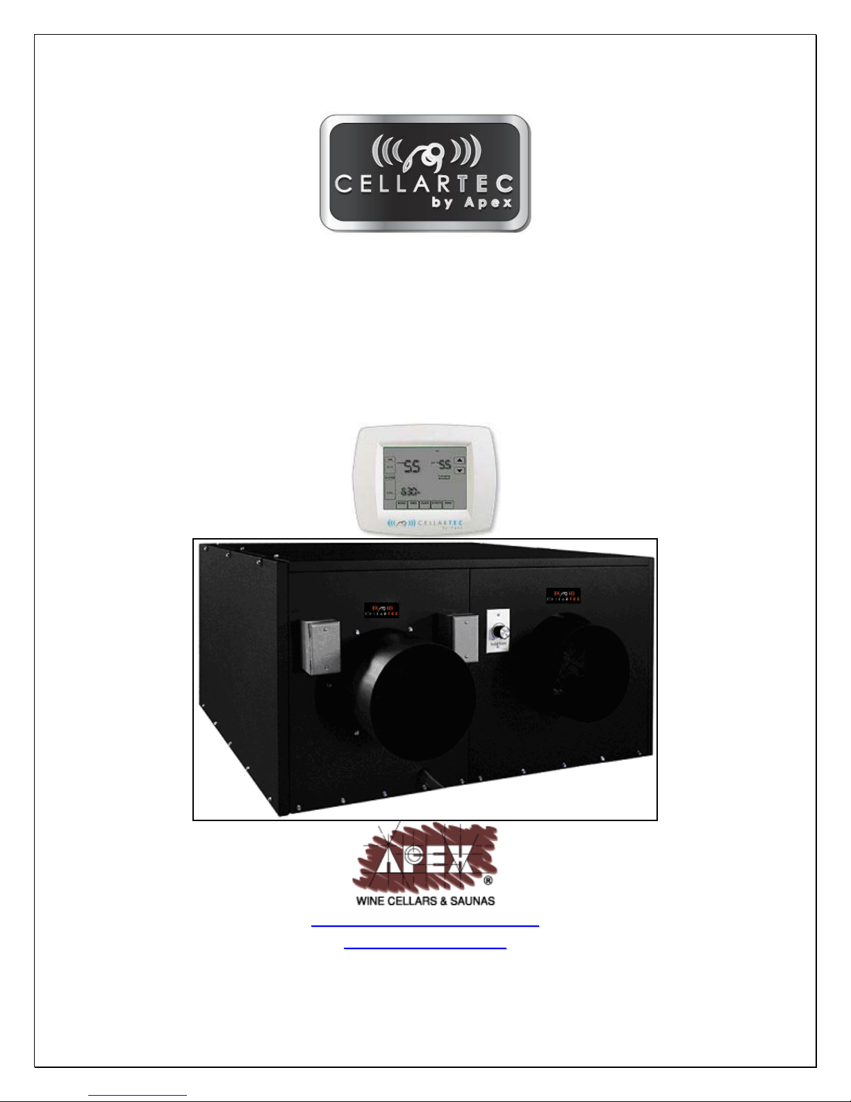
DS Series Ducted System
Installation, Operation & Care Manual
CellarTec 1/3 Ton-DS
CellarTec 1/2 Ton-DS
CellarTec 3/4 Ton-DS
READ AND SAVE THESE INSTRUCTIONS
wwwwww..aappeexxwwiinneecceellllaarrss..ccoomm
m
wwwwww..cceellllaarrtteecc..ccoom
Page 2

TABLE OF CONTENTS
Important Safety Information…..........................................2
Features & Specifications.…………………….……………..3
Cellar Construction.…………………………….……………..5
Installer’s Instruction…………….…..….……..……………..6
Temperature Control & Humidity Adjustment....…………9
Service Guide………………….……………………………...13
Electrical Wiring…………….……………………………...19
Care Guide…………………………………………………….26
User’ Troubleshooting…….………………………………...27
Customer Support……………………………………………30
Warranty……………………………………………………….31
- 1 -
Page 3
Important Safety Information
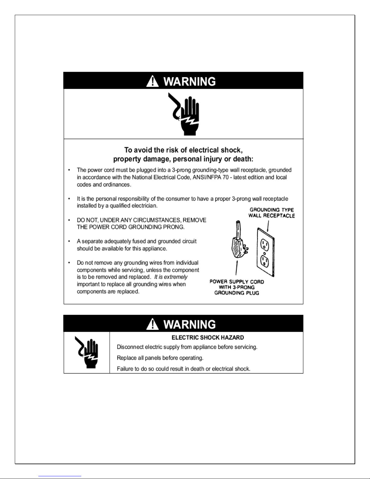
WARNING:
• DO NOT USE A GROUND FAULT INTERRUPTER (GFI).
• A DEDICATED CIRCUIT IS REQUIRED, 15 AMP FOR 1/3 Ton-DS AND 20
AMP FOR 1/2-3/4 Ton-DS.
- 2 -
Page 4
Features and Specifications
• CELLARTEC ducted system CellarTec 1/3-3/4 Ton-DS are designed and
used to provide a cold temperature between 50~65
insulated wine room at a normal environment.
• The wine room will maintain humidity of 50~70% RH even when the
environment becomes dry and humid. These temperatures and humilities
are optimized for long term storage of wine.
• The DS ducted systems are designed for both outdoor and indoor
installation.
• Back-curved impeller fans are good for total 50 ft long duct to cut the
operation noise.
• Self-contained ready for use with no extra refrigeration tubing in the field.
°F for a properly
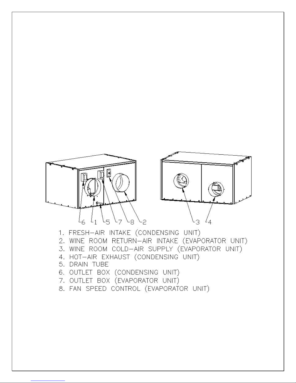
Fig. 1 CellarTec 1/3-3/4 Ton-DS FEATURES
Parts included:
Self-contained Cooling Unit
Temperature Controller + Air Sensor
- 3 -
Page 5
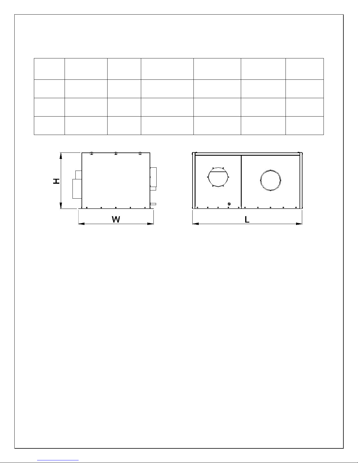
The dimensions and capacities are specified as follows:
BOTTLE
CAPACITY
(55/75°F)
1000
cu ft
1500
cu ft
2000
cu ft
MODEL
CellarTec
1/3 TON-
DS
CellarTec
1/2 TON-
DS
CellarTec
3/4 TON-
DS
DIMENSION
L”xW”xH”
45X34X23 4500/380
45X34X23 6500/490
45X34X25 8500/750
Btu/h
CFM
(55/90
°F)
REFRIGERANT ELECTRICAL WEIGHT(lb)
R134a 115V-60HZ-8A 140
R134a 115V-60HZ-14A 170
R134a 115V-60HZ-17A 220
Fig. 2 CellarTec 1/3-3/4 Ton-DS DIMENSIONS
CAUTION:
LOW AMBIENT TEMPERATURE KIT IS REQUIRED IF THE INSTALLATION
AREA WILL BE BELOW 50°F.
- 4 -
Page 6

Cellar Construction
This is only a guide and shall be considered as minimum requirements.
All interior walls and floors shall have a vapor barrier and a minimum of R11
insulation. All exterior walls and ceiling shall have a vapor barrier and a minimum
of R19 insulation. The vapor barrier shall be installed on the warm side of the
insulation. All joints, door frames, electrical outlets or switches and any pipes or
vents that go through the enclosure shall be sealed to prevent air and moisture
leakage into the room. Concrete, rock, and brick are not insulation or vapor
barriers.
Doors shall be of a minimum size, insulated to at least R11 and tightly sealed
with high quality weather stripping. Be sure to seal the bottom of the door and fill
gap between the door’s frame and wall before installing the cap molding.
In order to maintain 55 °F in the wine cellar, the ambient temperature
surrounding the enclosure shall not exceed the temperature of the enclosure by
more than 25 °F. No enclosure wall shall receive direct sun or strong wind.
Lighting shall be of low wattage, with a timer to insure lights are not left on when
the enclosure is not occupied.
The cooling system will not be able to maintain the proper temperature if fresh
moisture-laden air is constantly being introduced to the enclosure. Symptoms of
this condition are; unit runs all the time with only a slight reduction in temperature
and/or water overflows from the unit. Because of the temperature difference
between the inside and outside, very small cracks can allow large amounts of
outside air to enter into the enclosure. Please be aware that moisture can pass
through solid concrete, paint and wood. Often a newly constructed room contains
fresh wood, paint, concrete and other building materials. These materials contain
large amounts of moisture. When placed into operation in this type of
environment, the system will work harder to remove this extra moisture resulting
in increased “run” time.
- 5 -
Page 7
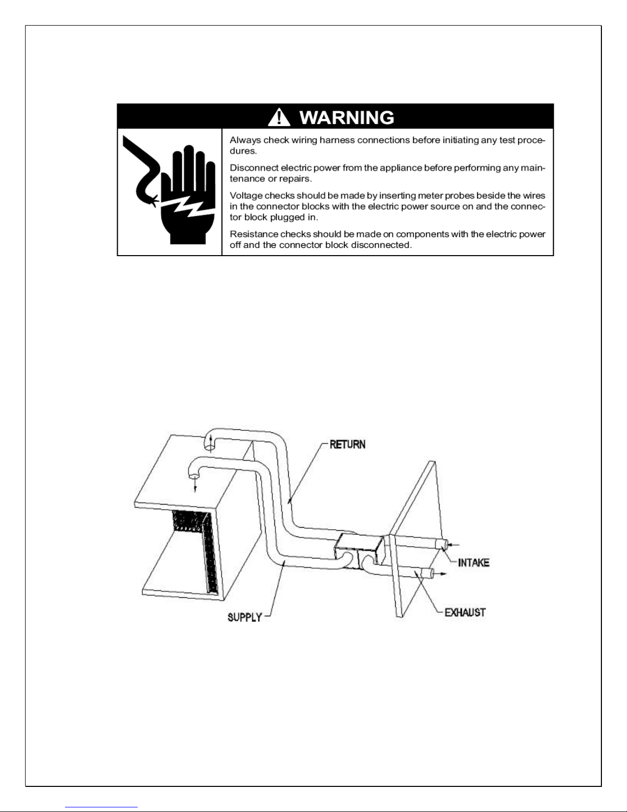
Installer’s Instruction
Federal law requires that CELLARTEC ducted cooling systems
be installed by an EPA certified refrigeration technician.
CELLARTEC ducted system is shipped ready for use only after a certified
refrigeration technician has properly installed the system. Proper installation is
critical. Apex can only warrant the quality of the components. The installation of
the system must be warranted by the installer. Installation of the system must be
done in accordance with all state and local building and electrical codes.
- 6 -
Fig. 3 DS System Installation
Page 8

1. Location
• Place the unit in a properly ventilated location. If it is not, heat exhausted
by the condensing unit will build up and the cooling system will not operate
properly.
• Cooling unit shall be elevated to avoid possible flooding and shaded from
direct sun. It shall not be exposed to temperatures higher than 110 °F or
lower than 50 °F (optional low ambient kit available).
• Leave minimum 5 feet clearance for hot air exhaust and leave minimum 1
foot clearance for the fresh air intake.
• There is a gravity drain line and the unit shall be installed level or with a
slight angle toward the drain connection.
• Supply air flow shall be unobstructed for at least 12” for free installation or
2” for deflector installation and return air shall be unobstructed for 6”.
• Overall combined supply + return or exhaust + intake duct length can be
up to 50 ft long.
2. Mounting
• The unit must be mounted on a floor or slab that is level and strong
enough to support up to 300lb.
• There are six ½” bolts required to secure the unit base.
3. Customer Wiring
• Use 14 AWG wires.
• If it is CellarTec 1/3 Ton-DS without low ambient kit, go to the next step.
Connect wires in the outlet box of the condensing unit to the power lines
• Connect wires in the outlet box of the evaporator unit to the temperature
controller and then connect the controller to the power lines.
4. Thermostat and Air Sensor(USE 18 GAUGE THERMOSTAT WIRE)
• The thermostat with a built-in air sensor can be installed in the wine room
5 ft above the floor in an area with good air circulation at average temp.
• If the thermostat is mounted outside the wine room, a remote air sensor is
required inside the wine room. The air sensor can be located in a well
circulated or in the return air area, but not the supply air or air dead area.
• If air sensor is in a return duct, the evaporator fans shall be running all the
time. Due to the temperature differential the temperature setting needs to
be adjusted in order to maintain the proper wine room temperature.
5. Air Flow (Evaporator unit)
• If the overall duct length is less than 50ft, it is necessary to check the air
flow to meet the specified CFM. It may use fan speed control to adjust the
system refrigeration performance to achieve 8-10
°F differential between
return air and supply air while wine room temperature is maintained 55°F.
Turn the control knob clockwise to decrease the air flow or counterclockwise to increase the air flow.
- 7 -
Page 9
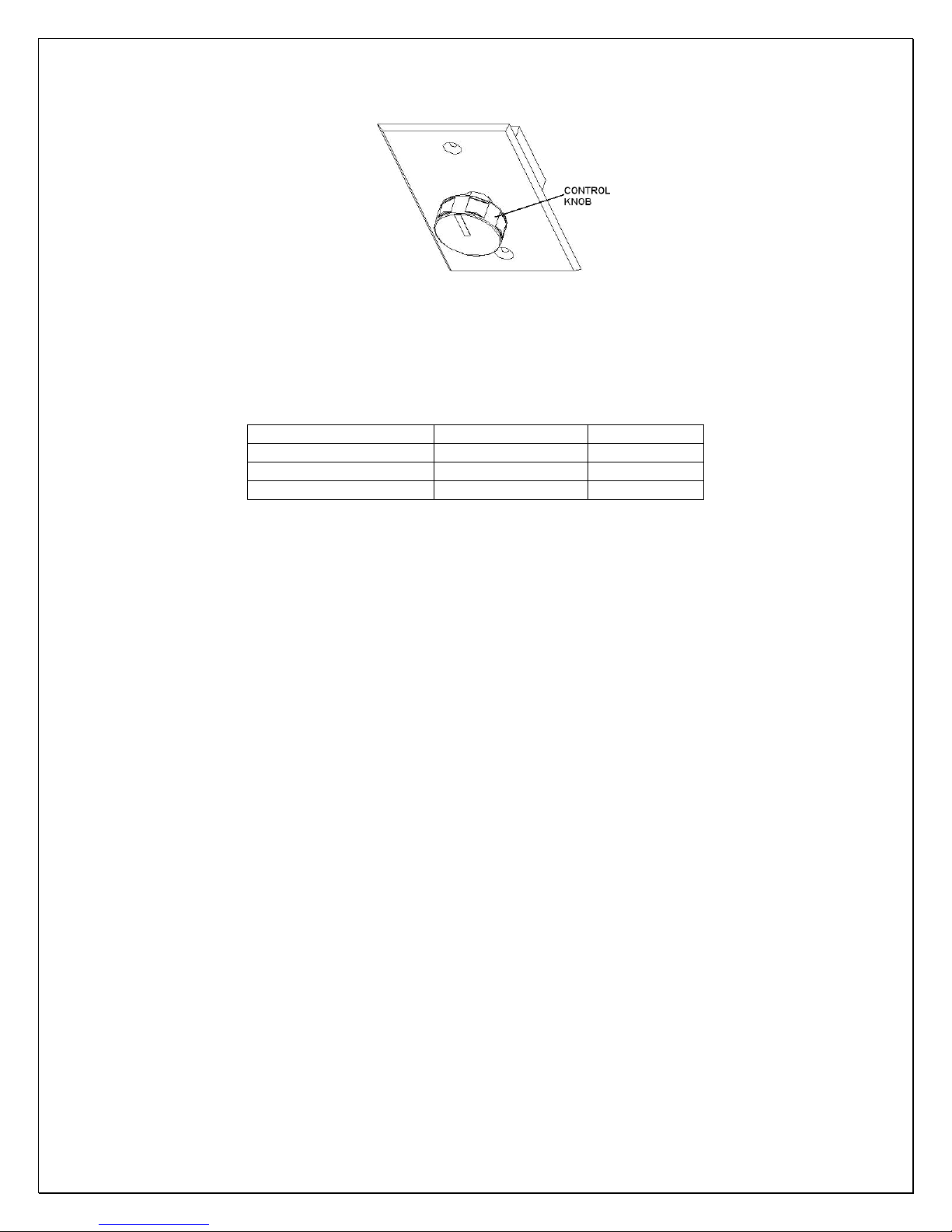
Fig. 4 Fan Speed Control
6. Intake and Exhaust Guards
• If the intake and exhaust are located outdoor, protection guards may be
required.
MODEL INSULATED DUCT DRAIN LINE
CellarTec 1/3 TON-DS 8” 7/8” OD
CellarTec 1/2 TON-DS 10” 7/8” OD
CellarTec 3/4 TON-DS 10” 7/8” OD
7. Unit Operating
• Turn on the fan speed control.
• Adjust thermostat temperature setting.
CAUTION:
IF THE CONDENSING UNIT IS EQUIPPED WITH A LOW AMBIENT
CONDITION KIT, DO NOT TURN ON THE COMPRESSOR UNTIL THE
CONDENSING UNIT HAS BEEN POWERD FOR 24 HOURS.
- 8 -
Page 10
Temperature Control & Humidity Adjustment
1. Temperature Setting
• Set the temperature at 55
• On initial start-up, the time required to reach the desired temperature
will vary, depending on the quantity of bottles, temperature setting
and surrounding temperature.
• Allow 24 hours to stabilize the temperature for each new temperature
setting operation
2. Use of the Programmable Thermostat
°F for the optimum aging of wine
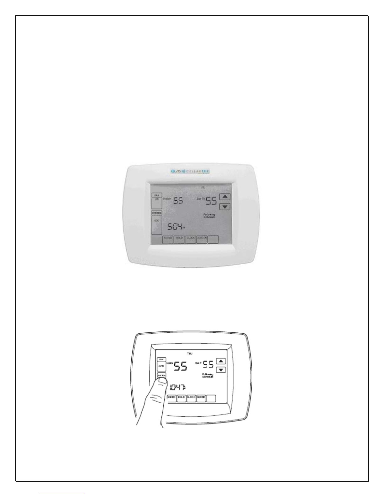
Fig. 5 Touchscreen Programmable Thermostat
1) System Setup
1. Press and release the SYSTEM Key.
- 9 -
Page 11
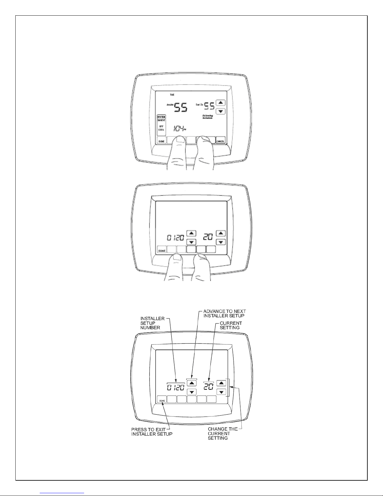
2. Press and hold the two blank keys on either side of the center blank key for
approximately five seconds until screen matches the screen below.
3. Press UP/DOWN advance keys to select setup number; press UP/DOWN
change keys to change settings.
4. Press the DONE key to exit the Installer Setup screen.
- 10 -
Page 12
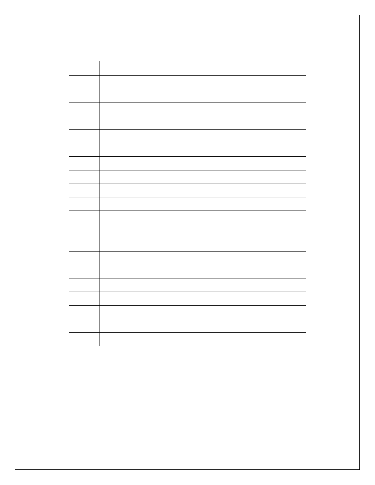
Factory Setup Menu
Setup
Number
0120 Date (Year Upper) Select first two digits of current calendar year
0130 Date (Year Lower) Select last two digits of current calendar year
0140 Date (Month) Select number for current calendar month
0150 Date (Day) Select number for current calendar date
0160 Schedule Options 0-nonprogrammable
0170 System Selection 6-cool only conventional
0220 Cycles Per Hour 2
0280 Continuous Backlight 0-not; 1-yes
0300 Changeover 0-manual
0320 Temperature Display 0-fahrenheit; 1-celsius
0330 Daylight Savings 0-off; 1-on
Setup Name Settings
0340 Remote Air Sensor 0-no; 3-indoor
0380 Indoor Dehumidification 0-no
0580 Min Compressor Off 5-five minutes off
0610 Min Cool Temp
0640 Clock Format 12-12 hour; 24-24 hour
0660 Extended Cool Fan On 0-0 seconds
0670 Keypad Lockout 0-unlocked; 2-fully locked
0690 Cool Temp Control 2-standard
0700 Temperature Offset 0-no
50
°F
NOTES:
• The setup 0660 can be used to increase the humidity in the wine cellar. The
higher the setting is, the higher the humidity will be.
2) System Test
1. Enter the system setup, and press DOWN key to select setup number.
“TEST” appears at the end of the installer setup number.
2. Press the keys below to test.
- 11 -
Page 13
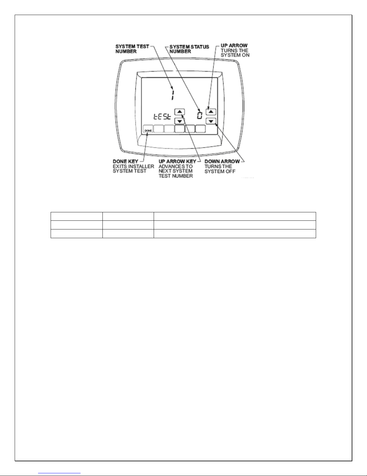
Fig. 6 System Test
Test Number Test Type Description
1 cooling 1-on; 0-off
2 fan 1-on; 0-off
3) Clock Setting
1. Enter the system setup and set 670 = 0 to unlock screen, then exit.
2. Press CLOCK key; press UP/DOWN keys to change clock.
3. Press DONE key to exit.
4. Enter the system setup and set 670 = 2 to lock screen, then exit.
4) Temperature Setting
1. Enter the system setup and set 670 = 0 to unlock screen, then exit.
2. Press UP/DOWN keys to modify temperature.
3. Enter the system setup and set 670 = 2 to lock screen, then exit.
5) Remote Air Sensor
Enter the system setup and set 340 = 3, then exit
6) Humidity Display
It only displays the humidity where the thermostat is installed. The humidity
level is shown in the lower right corner of the screen.
- 12 -
Page 14

Service Guide
CAUTION:
• ALWAYS USE THE SUPERHEAT AND SUBCOOLING, PRESSURE
READINGS TO CHARGE REFRIGERANT PROPERLY, THE LISTED
CHARGES ARE FOR REFERENCE ONLY.
• CHARGE 15% MORE REFRIGERANT IN THE SUMMER IF THE UNIT IS
EQUIPPED A LOW AMBIENT CONDITION KIT
NOTES:
• THE VALVE CONNECTION SIZES OF CONDENSING UNIT AND THE LINE
CONNECTION SIZES OF EVAPORATOR UNIT ARE NOT NECESSARY
THE SAME AS THE ABOVE SPECIFIED LINE SIZES.
• IF THE CONDENSING UNIT IS INSTALLED ABOVE THE EVAPORATOR
UNIT, USE THE SUCTION LINE ONE LISTED SIZE SMALLER.
• EXPANSION AND SOLENOID VALVES ARE INSTALLED ON LIQUID LINE.
1. Refrigeration Piping, Evacuating, Charging and Starting
• The installation order starts from condensing unit (including the receiver,
discharge valve), liquid line filter-drier, moisture-liquid indicator/sight glass,
liquid line, to evaporator unit (including liquid line connection, solenoid
valve, expansion valve, and suction line connection), returning to insulated
suction line, suction valve and then condensing unit.
• Use inverted siphons to prevent liquid from flooding back to the
compressor and aid oil returning to the compressor.
• Charge the system after pipe brazing, leak testing and evacuating. Liquid
must always be charged into the hide side.
• It may use fan speed control to adjust the air flow to achieve the specified
CFM. Turn control knob clockwise to the lowest speed position, locate and
adjust the minimum speed setting (on the side or front) with screw driver.
Rotate the setting clockwise to decrease minimum speed or counterclockwise to increase minimum speed). The minimum speed should be
adjusted until it supplies the required CFM. The fan will run from this
preset minimum speed to full speed with the control knob at lowest and
highest speed position.
• The subcooling at the condensing unit shall be around 10
may be complete when there are no more bubbles forming in the sight
glass.
• Head pressure: 125-150 psig at 70 -90 °F ambient temperatures.
• The evaporator’s constant pressure expansion valve is set around 35-
40
°F at factory. This pressure setting gives a dew point to maintain the
humidity for storing wine.
• Suction pressure: Adjust the AXV to 30-35 psig.
• The temperature split between return air and supply air shall be 8-10
55°F wine room temperature.
° F. The charge
°F at
- 13 -
Page 15
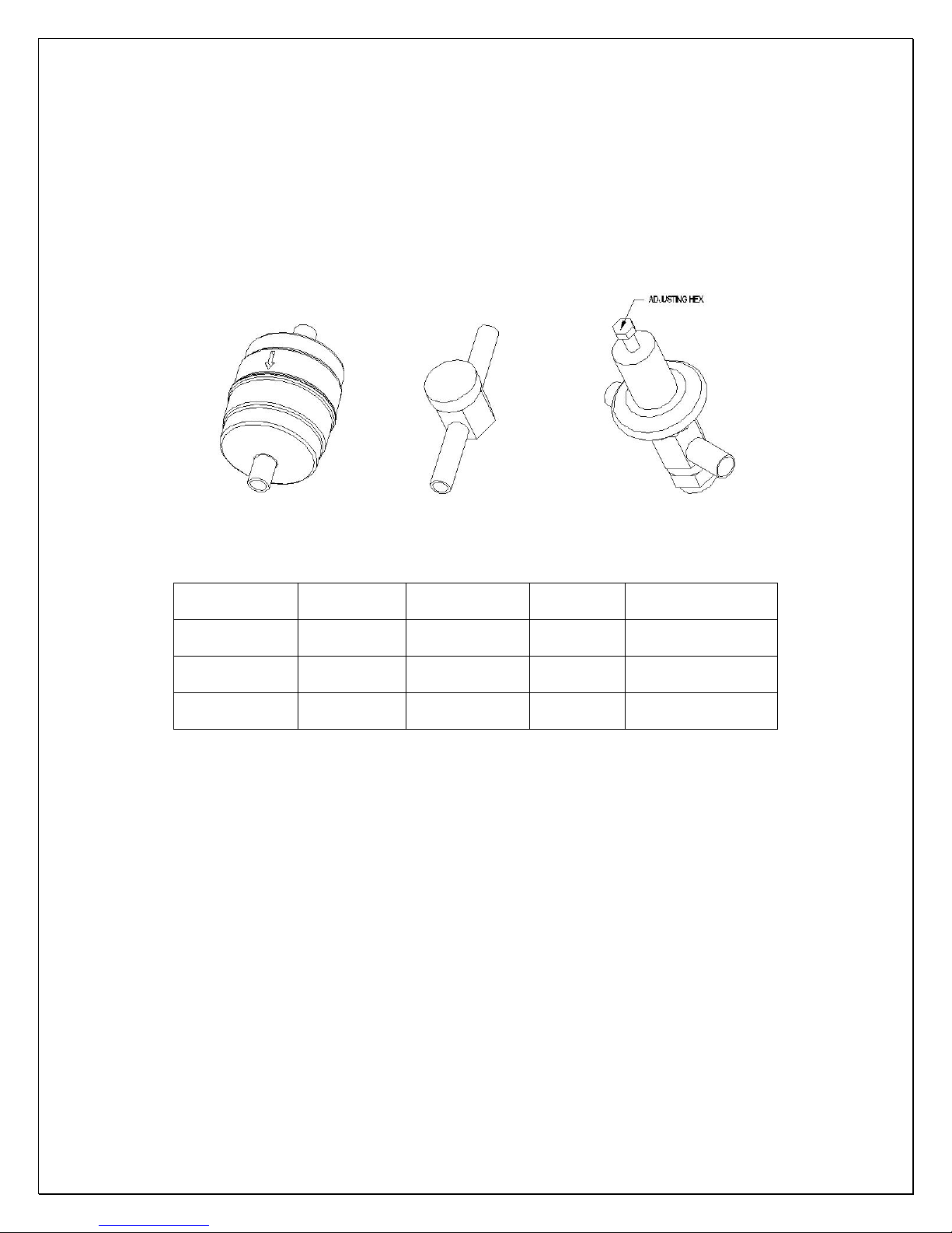
• The superheat at the evaporator unit shall be around 9-18°F under low -
high heat load at normal ambient temperatures.
• If the superheat is high, check the subcooling first to know if the refrigerant
charge is sufficient. If the charge is not sufficient, add more refrigerant. If
the charge is good, then increase the evaporator suction pressure by
turning the hex nut (5/16”) clockwise.
• If the superheat is low, then decrease the evaporator suction pressure by
turning the hex nut (5/16”) counter-clockwise.
Fig. 7 Liquid Filter Fig. 8 Sight Glass Fig. 9 Expansion Valve
The line sizes and refrigerant charges are listed as follows.
MODEL
CellarTec 1/3
TON-DS
CellarTec 1/2
TON-DS
CellarTec 3/4
TON-DS
LIQUID
LINE
1/4" OD 1/2” OD 7/8” OD 24 OZ
1/4" OD 1/2” OD 7/8” OD 32 OZ
3/8" OD 5/8” OD 7/8” OD 40 OZ
SUCTION
LINE
DRAIN
LINE
CHARGE (R134A)
2. Discharge/Suction Valve Operation (Condensing unit)
Back Position: Normal operation, process and manometer port closed
Front Position: Liquid/suction line connection closed
Middle Position: All ports open for evacuation, charge and manometer reading
- 14 -
Page 16
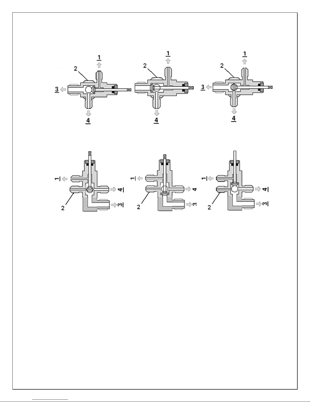
BACK POSITION FRONT POSITION MIDDLE POSITION
Fig. 10 ROTALOCK Valve Operation
BACK POSITION FRONT POSITION MIDDLE POSITION
Fig. 11 Base Valve Operation
1 - Process & Manometer; 2 – Receiver Discharge)/Compressor Suction
3 – Liquid Line/Suction Line; 4 - Pressure Control
3. Use of the adjustable pressure control (if applicable for pump-down)
Suction pressure setting: Cut out=5 psig; Cut in=25 psig; Differential=20 psig
Head pressure setting: Cut out=230 psig; Cut in=150 psig; Differential=80 psig
It may need to adjust the setting in the field to get the right cycle time.
- 15 -
Page 17
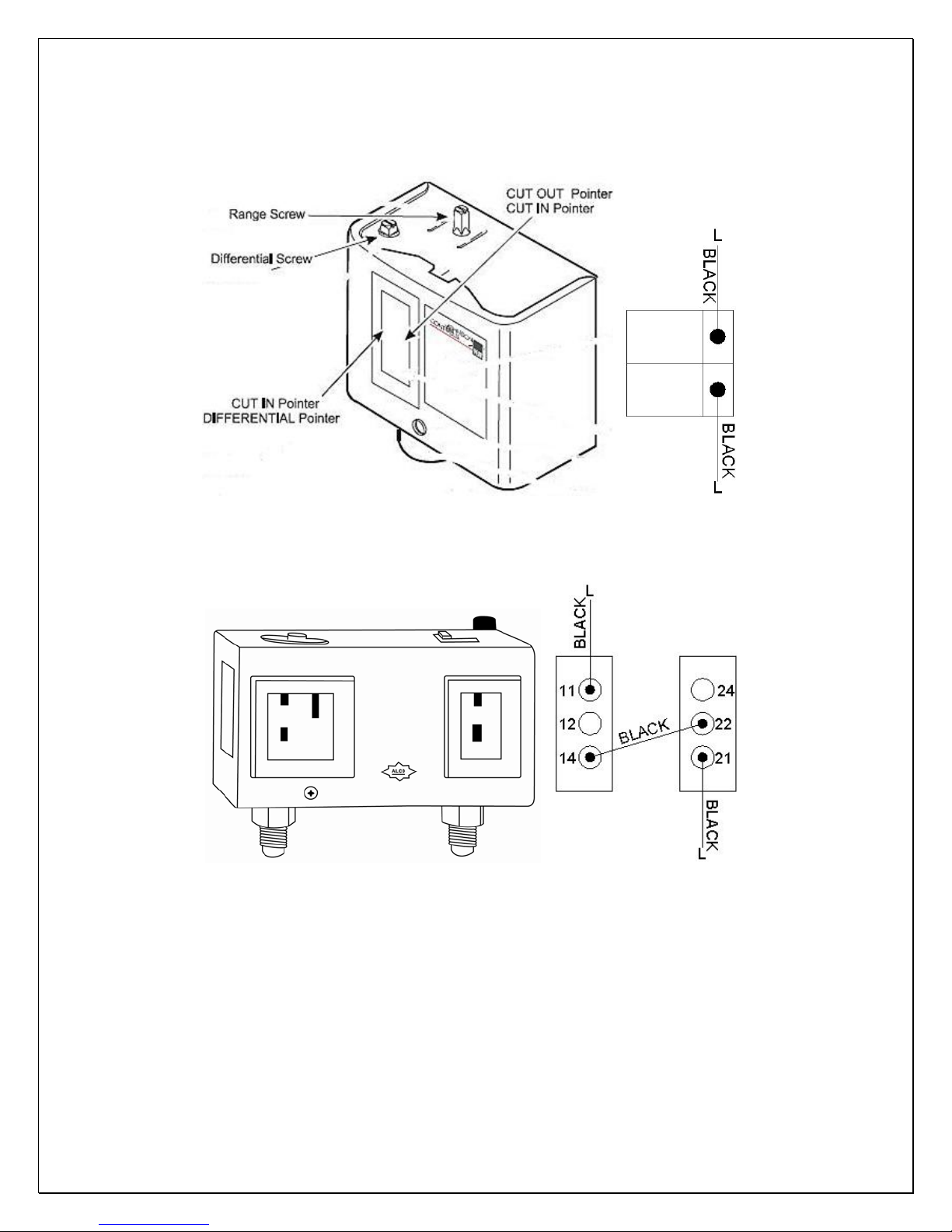
A. Single Control
B. Dual Control
Fig. 12 Single Adjustable Pressure Control
Fig. 13 Dual Adjustable Pressure Control
4. Use of the encapsulated low pressure control (if applicable)
Fixed suction pressure setting: Cut in = 32 psig; Cut out = 10 psig
- 16 -
Page 18
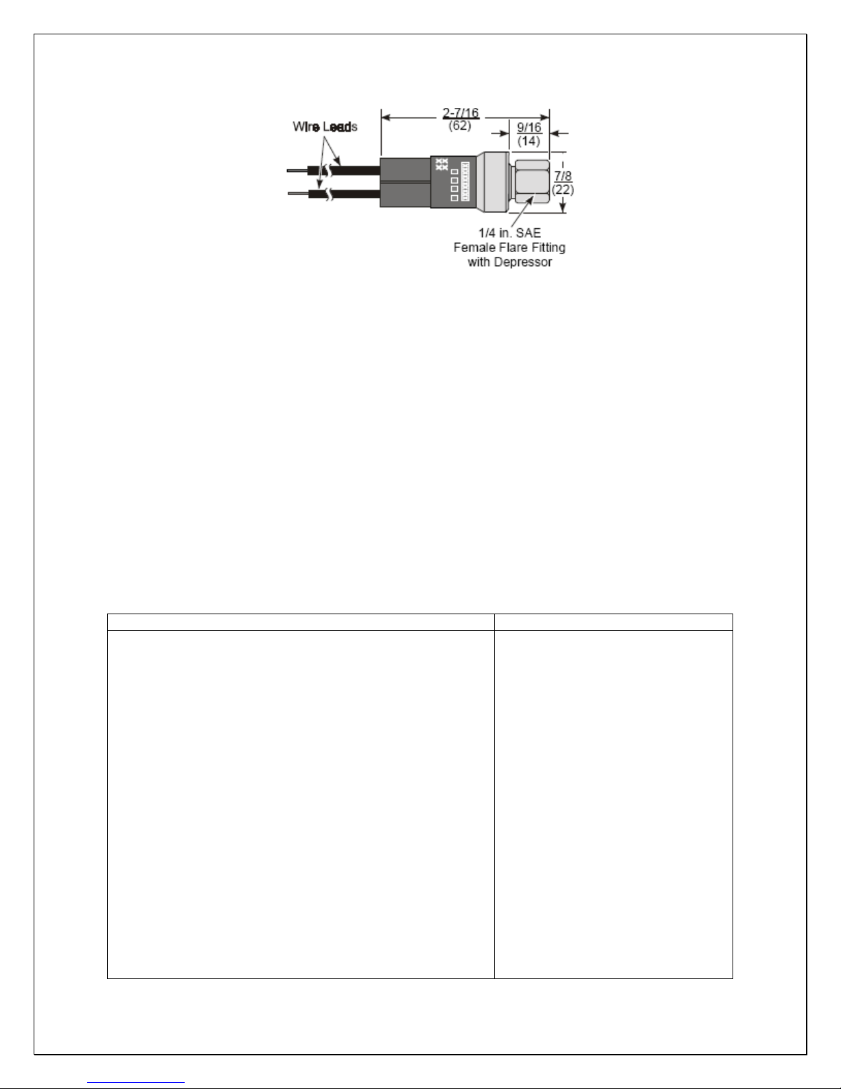
Fig. 14 Fixed Pressure Control
5. Use of the condenser fan control (if applicable for low ambient kit)
Head pressure setting: Cut in=170 psig; Cut out=120 psig; Differential=50 psig
It may need to adjust the setting in the field to avoid fan short cycle.
6. Use of the crankcase heater (if applicable for low ambient kit)
The crankcase heater is installed around the lower part of the compressor and
shall be turned on all the time. The heater is self-modulated.
7. Pressure, Superheat and Subcooling Readings
CAUTION:
THE VALVES MUST BE IN THE MIDDLE POSITIONS TO READ PROPERLY.
Complaint Possible Causes
a. High suction pressure and low head pressure
b. High suction pressure and low head pressure
Low superheat and low subcooling
c. High suction pres sure and high head pressure
Low superheat and high subcooling
d. High to normal suction pressure and high head pressure
Low subcooling
e. High suction pressure and high head pressure
Low subcooling
f. High suction pressure and high head pressure
High superheat
g. Low suction pressure and low head pressure
High superheat and low subcooling
h. Low suction pressure and low to normal head pressure
High superheat and high subcooling
i. Low suction pressure and low head pressure
Low subcooling
j. Low suction pressure and low head pressure
Low superheat and low subcooling
k. Low suction pressure and low to normal head pressure
High superheat and normal to high subcooling
a. Compressor may be bad
b. Expansion valve opened, too
much oil
c. Overcharge
d. Non-condensable gas
e. Air restricted, dirty condenser,
bad condenser fans
f. High room temperature, high
evaporator load
g. Undercharge
h. Liquid line restricted after
receiver, solenoid valve
restricted
i. Suction line restricted
j. Air restricted at evaporator,
evaporator iced
k. Evaporator restricted
- 17 -
Page 19
l. Low suction pressure and normal head pressure
High superheat and normal subcooling
m. Low suction pressure and high head pressure
High superheat and high subcooling
n. Low suction pressure and high head pressure
High superheat and high subcooling
o. low to normal suction pressure and high head pressure
High to normal superheat and high subcooling
8. Condensing Unit Troubleshooting
Unit not running
a. Incorrect power supply
b. Incorrect or loose wirings
c. Failed components
d. Liquid refrigerant in the compressor
e. Low pressure switch shutting down the system
a. Check for proper voltage
b. Check all wirings and connections
c. Check start relay, start capacitor, overload
d. Call service for OEM information
e. Check for system restriction or low
l. Expansion valve restricted
m. Both evaporator and condenser
restricted
n. Liquid line restricted before
receiver
o. Condenser restricted
protector, compressor.
refrigerant
- 18 -
Page 20
Electrical Wiring
CAUTION:
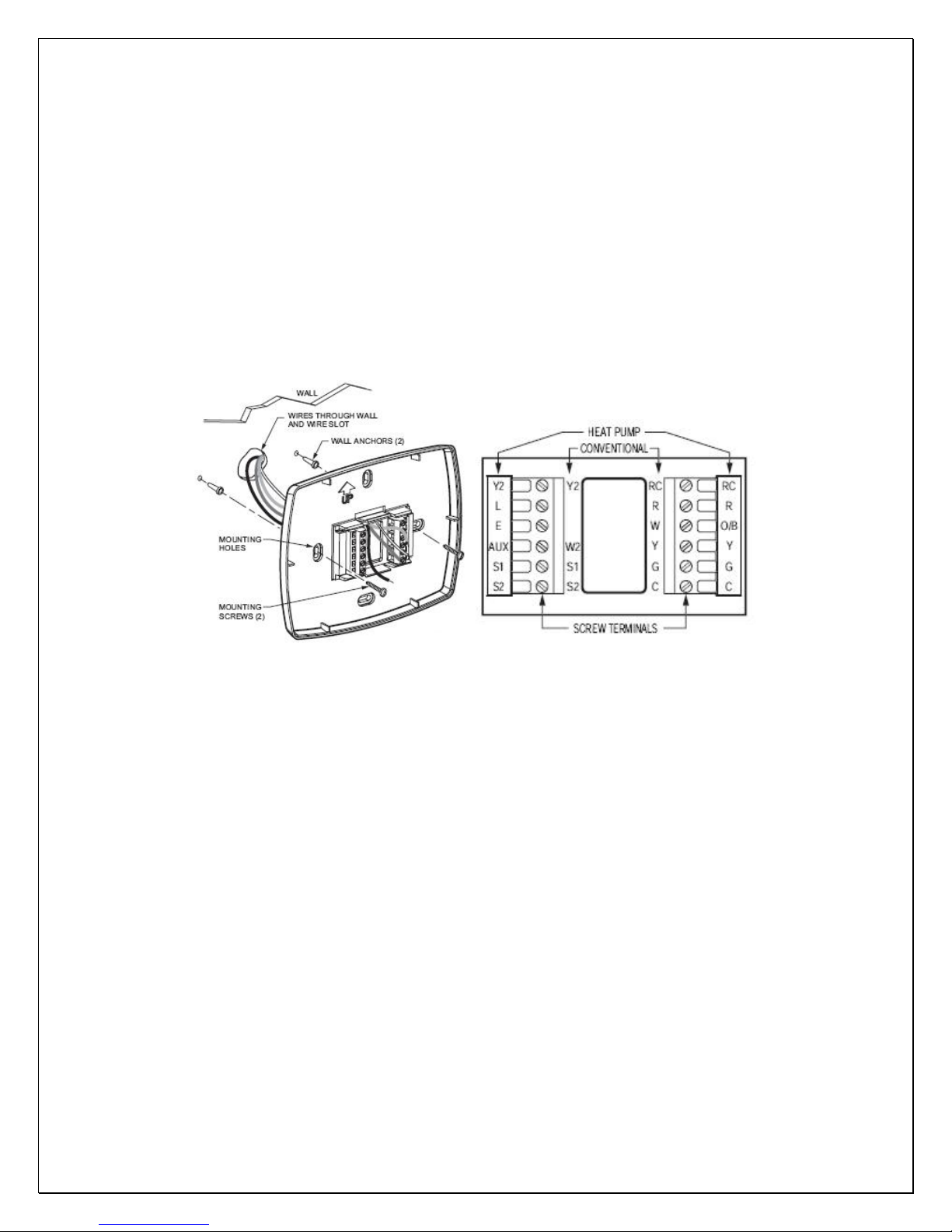
• USE 14 GAUGE WIRE FOR POWER LINE WIRING.
• USE 18 GAUGE WIRE FOR THERMOSTAT AND SENSOR.
• IF EQUIPPED WITH LOW AMBIENT CONDITION KIT, USE LOW AMBIENT
TEMPERATURE WIRING DIAGRAMS. TURN OFF THE COMPRESSOR
BEFORE POWER THE CONDENSING UNIT. ONLY TURN ON THE
COMPRESSOR AFTER THE CONDENSING UNIT HAS BEEN POWERED
FOR 24 HOURS.
Fig. 15Thermostat Installation
- 19 -
Page 21
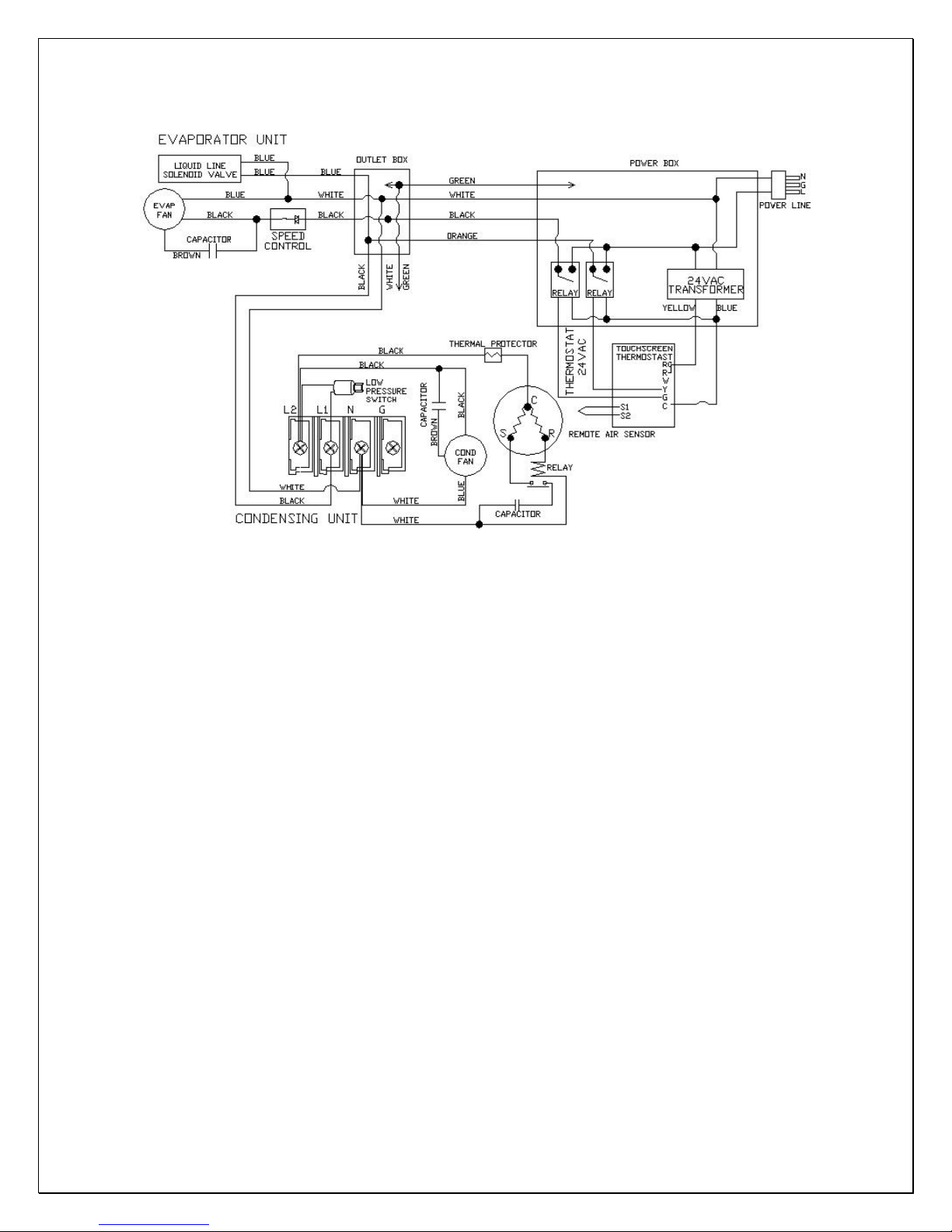
Fig. 16 CellarTec 1/3 Ton-DS Electrical Wiring Diagram
- 20 -
Page 22
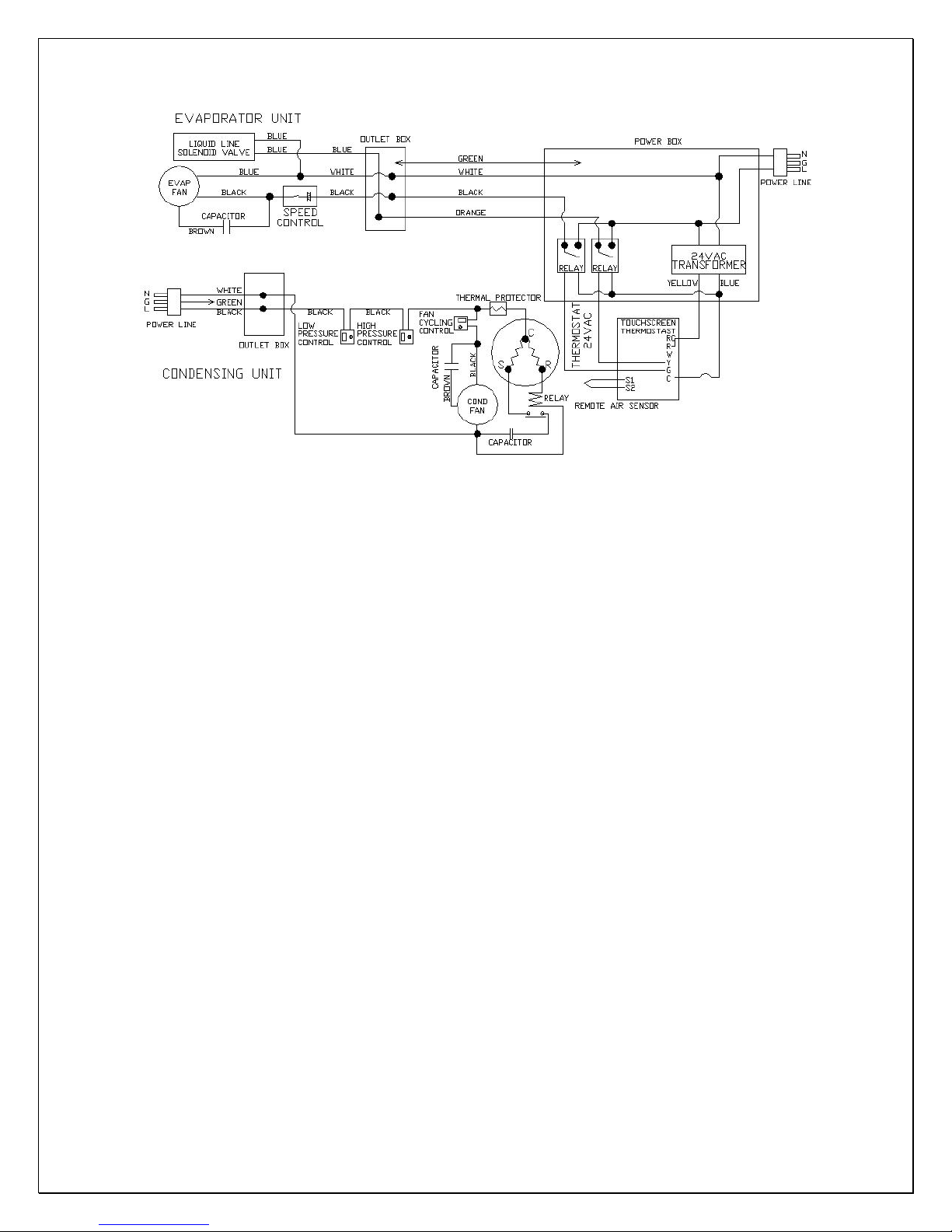
Fig. 17 CellarTec 1/2 Ton-DS Electrical Wiring Diagram
- 21 -
Page 23
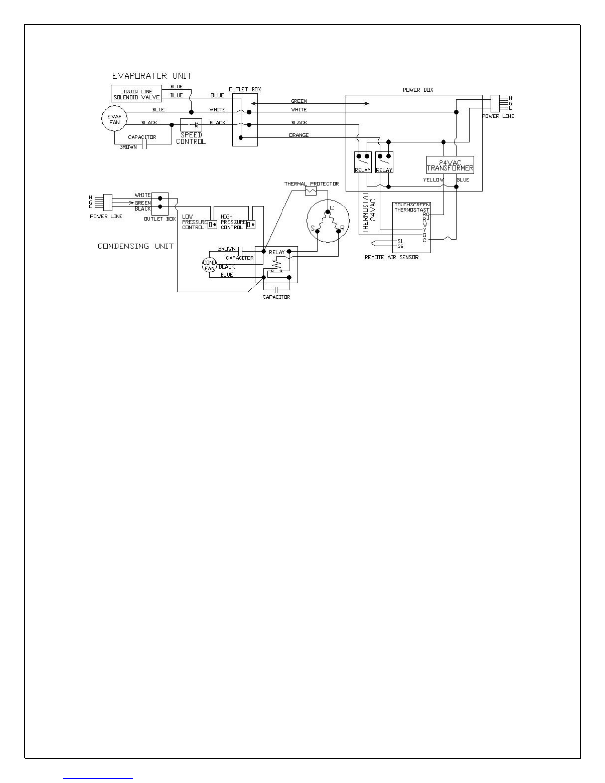
Fig. 18 CellarTec 3/4 Ton-DS Wiring Diagram
- 22 -
Page 24
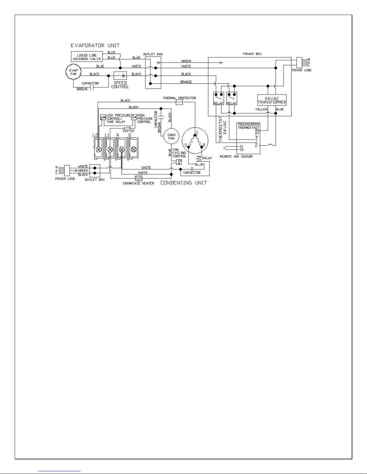
Fig. 19 Low Ambient Temperature
CellarTec 1/3 Ton-DS Electrical Wiring Diagram
- 23 -
Page 25
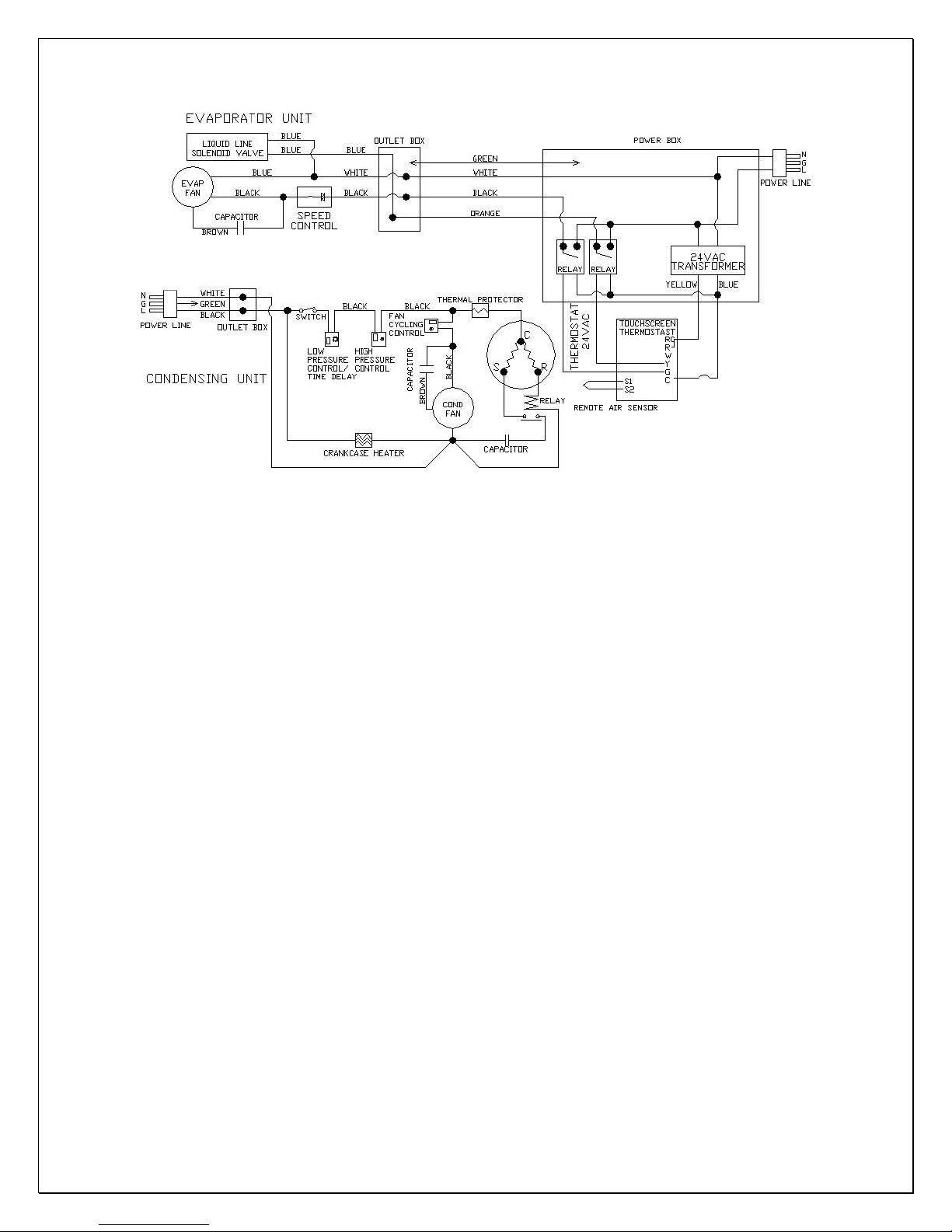
Fig. 20 Low Ambient Temperature
CellarTec 1/2 Ton-DS Electrical Wiring Diagram
- 24 -
Page 26
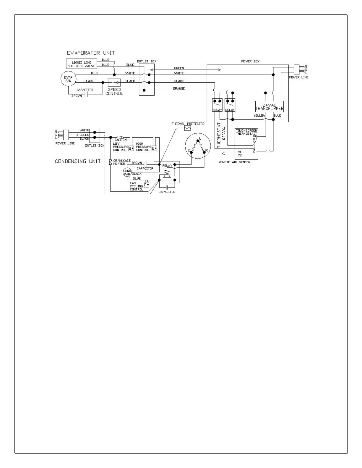
Fig. 21 Low Ambient Temperature
CellarTec 3/4 Ton-DS Wiring Diagram
- 25 -
Page 27
Care Guide
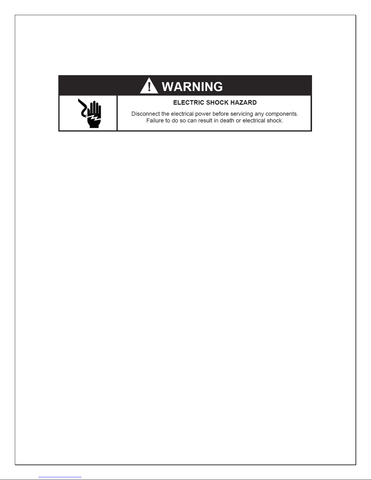
In general, always unplug system or disconnect power while doing care.
1. Coil Cleaning
• Clean the condenser coil regularly. Coil may need to be cleaned at least
every 6 months.
• Unplug the system or disconnect power.
• Use a vacuum cleaner with an extended attachment to clean the coil when it
is dusty or dirty.
• Plug cooling system or reconnect power.
2. Moisture Removing
• Remove the extra condensate if it is accumulated in the wine cellar at high
ambient temperature and humidity.
- 26 -
Page 28
User’s Troubleshooting
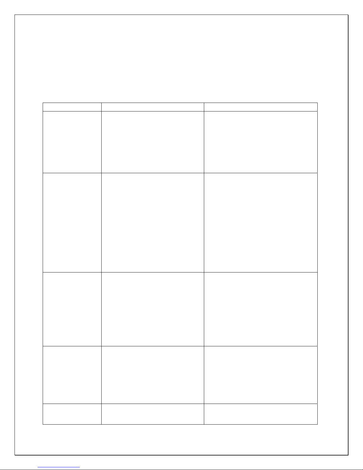
This Troubleshooting Chart is not prepared to replace the training required for a
professional refrigeration service person, not is it comprehensive
Troubleshooting Chart
Complaint Possible Causes Response
1.Unit not
running
2.Displaying
Temperature
fluctuating
3.Temperature
high, but
displaying
temperature
low, unit
stopping and
starting with
short
running time
4.Temperature
high,
compressor
stopping and
starting but
short
running time
5.Not cooling
or
a. No power
b. Power cord unplugged
c. Setting higher than ambient
temperature
d. Defrost light blinking
e. Compressor light blinking
f. Incorrect or loose wirings.
g. Low voltage.
a. Air sensor When using an air sensor, the wine
a. air sensor contacting the
evaporator
b. Short circuit of air flow between
supply and return air
c. Setting too high
d. Failed temperature controller
and air sensor
a. Incorrect voltage
b. Failed components
c. Improper condenser airflow
d. Dirty condenser
e. Overcharge of refrigerant
f. Discharge or suction pressure
too high
a. Improper room insulation & seal
b. Room too large
a. Check power at receptacle & fuses
b. Check for power cord plug
c. Lower temperature setting
d. Unit is under defrost mode
e. Unit waits for anti-short cycle delay
f. Check all wirings and connections
g. Contact an authorized electrician
bottle temperature is mainly controlled
by the average air temperature. If the
set-point is 55
the cooling unit turns on at 59
temperature and turns off at 55
temperature. The average air
temperature is 57
temperature is around 57+/-0.5
air is light enough to change so quickly
that it maintains relatively constant
average temperature that would prevent
wine bottle temperature from varying.
a. Move the air sensor away from the
evaporator
b. Deflect the supply air down
c. Lower setting
d. Call service for diagnosis
a. Check for voltage
b. Check compressor windings, start
relay and overload protector.
c. Check for condenser fan
d. Clean condenser
e. Call service for removing refrigerant
f. Call service for OEM information
a. Check for insulation, gasket and
door opening
b. Check for excessive size
°F with a differential 4 °F,
°F of air
°F of air
°F, and then the wine
°F. The
- 27 -
Page 29
temperature
too high and
running
continually
6.Unit running
too long
7.Evaporator
freezing up
8.Water leak
9.Circuit
tripping
c. Ambient temperature too high
d. Exhaust restricted
e. Malfunctioning fans
f. Improper evaporator or
condenser airflow
g. Dirty Condenser
h. Iced evaporator
i. Sealed system problem
j. Undercharge or overcharge
a. Improper room insulation & seal
b. Exhaust restricted
c. Room too large
d. Ambient temperature extremely
high
e. Dirty Condenser
a. Evaporator air flow restriction
b. Unit not stopping due to air leak,
high ambient temperature or low
setting
c. Low ambient temperature
d. Bad thermostat or sensor
e. Refrigerant low or leak
f. Expansion valve blockage
a. Unit not level
b. Drain line restricted
c. Drip tray leak
d. Very high humidity
e. Wine room air leak
a. Incorrect fuse or breaker
b. Incorrect wirings
c. Overcharge o f refrigerant
d. Condenser air restriction
e. Failed components
c. Check for installation location
d. Leave minimum 3 feet clearance for
e. Check for both evaporator and
f. Check for air restrictions
g. Clean condenser
h. Defrost and reset temperature
i. Call service for checking loss of
j. Call service to add or remove
a. Check for insulation, gasket and door
b. Leave minimum 3 feet clearance for
c. Check for excessive size
d. Check for installation location or
e. Clean condenser
a. Check for fans, CFM
b. Check for seal, door opening,
c. Defrost the unit
d. Check for thermostat and sensor
e. Check for sealed system leakage
f. Check for low side pressure
a. Check for installation
b. Check drain line
c. Check for if water leak but no
d. Use dehumidifier
e. Check for air leak and if
a. Check for proper fuse or breaker
b. Check for wirings and connections
c. Call servi ce for re moving refrigerant
d. Check condenser fan
e. Call service
the exhaust side and leave minimum
1 foot clearance for the fresh air
intake side
condenser fans
refrigerant or restrictions
refrigerant
opening
the exhaust side and leave minimum
1 foot clearance for the fresh air
intake side
increase setting
ambient temperature and setting
overflow
condensation on the cooling unit
- 28 -
Page 30
10.Noisy
operation
a. Mounting area not firm
b. Loose parts
c. Compressor overloaded due to
high ambient temperatures or
airflow restriction
d. Malfunctioning components
a. Add support to improve installation
b. Check fans, cabinet washers, tubing
contact and loose screws.
c. Check for airflow blockage
d. Call service for checking Internal
loose, inadequate lubrication and
incorrect wirings
- 29 -
Page 31

Customer Support
If you still have problems, please contact us at:
Apex
17631 South Susana Road
Rancho Dominguez, CA 90221
Tel: (310) 886-3332
Fax: (310) 886-3310
Email: [email protected]
- 30 -
Page 32

Warranty
Thank you for choosing an Apex cooling unit.
Please enter the complete model and serial numbers in the space provided:
Model_________________________________________________________
Serial No.______________________________________________________
Attach your purchase receipt to this owner’s manual.
1. Limited Warranty
APEX warrants its products, parts only, to be free from defects due to
workmanship or materials under normal use and service for twelve months after
the initial sale. If the product is defective due to workmanship or materials, is
removed within twelve months of the initial sale and is returned to APEX, in the
original shipping carton, shipping prepaid, APEX will at its option, repair or
replace the product free of charge.
This warranty constitutes the entire warranty of the APEX with respect to its
products and is in lieu of all other warranties, express or implied, including any of
fitness for a particular purpose. In no event shall APEX be responsible for any
consequential damages what is so ever. Any modification of APEX products shall
void this warranty.
Service under Warranty
This service is provided to customers within the continental UNITED STATES
only. APEX cooling units are warranted to produce the stated number of BTU/H.
While every effort has been made to provide accurate guidelines, APEX can not
warranty its units to cool a particular enclosure.
In case of failure, APEX cooling units must be repaired by the factory or its
authorized agent. Repairs or modifications made by anyone else will void the
warranty.
Shall an APEX cooling unit fail, contact the dealer for instructions, do not return
the unit to the factory without authorization from APEX. If the unit requires repair,
re-pack it in the original shipping carton and return it to the factory, shipping
prepaid. APEX will not accept COD shipments. If the unit is determined to be
faulty and is within the twelve month warranty period APEX will, at its discretion,
- 31 -
Page 33

repair or replace the unit and return it free of charge to the original retail
customer. If the unit is found to be in good working order, or beyond the initial
twelve month period, it will be returned freight collect.
2. Limitation of Implied Warranty
APEX’S SOLE LIABILITY FOR ANY DEFECTIVE PRODUCT IS LIMITED TO,
AT OUR OPTION, REPAIRING OR REPLACING OF UNIT.
APEX SHALL NOT BE LIABLE FOR:
DAMAGE TO OTHER PROPERTY CAUSED BY ANY DEFECTS IN THE UNIT,
DAMAGES BASED UPON INCONVENIENCE, LOSS OF USE OF THE UNIT,
LOSS OF TIME OR COMMERCIAL LOSS, ANY OUTER DAMAGES,
WHETHER INCIDENTAL, CONSEQUENTIAL OR OTHERWISE.
THIS WARRANTY IS EXCLUSIBE AND IS IN LIEU OF ALL OTHER
WARRANTIES, EXPRESSED OR INPLIED, INCLUDING BUT NOT LIMITED
TO, IMPLIED WARRANTIES OF MERCHANTABILITY OR FITNESS FOR A
PARTICULAR PURPOSE.
While great effort has been made to provide accurate guidelines APEX cannot
warrant its units to properly cool a particular enclosure. Customers are cautioned
that enclosure construction, unit location and many other factors can affect the
operation and performance of the unit. There for suitability of the unit for a
specific enclosure or application must be determined by the customer and cannot
be warranted by APEX.
- 32 -
 Loading...