

CellarCool Ultimate 3300-R FD, Ultimate 4400, Ultimate 8800-R, Ultimate 4400-R, Ultimate 8800-R FD Owner's Manual
...Page 1
ULTIMATE SERIES
OWNER’S MANUAL
Ultimate 3300
Ultimate 4400
Ultimate 8800
Page 2

CellarCool copyrights this manual, the product design, and the design concepts, with all rights reserved. Your rights with regard to
the hardware and manual are subject to the restrictions and limitations imposed by the copyright laws of the USA. Under copyright
laws, this manual may not be copied, reproduced, translated, transmitted, or reduced to any printed or electronic medium or to any
Every effort has been made to ensure that the information in this manual is accurate. CellarCool is not responsible for printing or
CellarCool reserves the right to make corrections or improvements to the information provided and to the related hardware at any
Mention of third-party products is for informational purposes only and constitutes neither an endorsement nor a recommendation.
Conforms to ANSI/UL Std 427
Certied to CAN/CSA Std C22.2 No. 120
We manufacture, test and certify 100% of our wine cooling units in
the USA. By sourcing the best components and closely controlling our
manufacturing processes, we can assure the highest-quality,
lowest defect manufacturing rates in the industry.
Copyright © 2012. CellarCool. All rights reserved.
machine-readable form, for any purpose, in whole or in part, without the written consent of CellarCool.
clerical errors.
time, without notice.
Vinothèque and CellarCool are registered trademarks, and ECE is a trademark of CellarCool. All rights reserved.
CellarCool assumes no liability with regard to the performance or use of these products.
06.10.2015
Page 3

TABLE OF CONTENTS
Introduction ............................................................2
Before You Start ........................................................3
Receiving & Inspecting the Unit ........................................4
Quick Reference Guide .................................................5
Standard Controller Layout ..................................................6
Remote Controller Layout ...................................................
Fan Speed & Unit Specications ..............................................7
Preparing the Wine Cellar ..............................................8
Preparing the Unit for Installation ......................................11
Through-the-Wall Installation
Preparing the Installation Location ...........................................12
Optional Exterior Grille ......................................................14
Installing the Unit ...........................................................15
Condensation Drain Line ...............................................16
Liquid Measuring Thermostat System (Bottle Probe) ..................17
Multi-Speed Fan Control ................................................18
Unit Operation .......................................................... 19
Standard Controller
Functions ...................................................................20
Alarm Codes ................................................................21
CPSM (Customer Preference Selection Mode) .................................21
Ultimate 3300, 4400, & 8800 Wiring Diagram ..........................22
Troubleshooting Guide .................................................24
Maintenance Schedule .................................................26
Technical Assistance & Accessories .....................................27
Installation Terms & Conditions ........................................28
Page 4
INTRODUCTION
Customer Service
Thank you for purchasing a CellarCool Ultimate Series cooling unit. We strive to provide the highest-quality products and the
best possible customer service. If you have any questions about your CellarCool unit, please call us at 1-800-343-9463 or visit
www.cellarcool.com.
Using the Manual
This manual is intended to assist in the proper installation and maintenance of the CellarCool cooling unit. In order to ensure the
longevity of your cooling unit, the equipment should be installed correctly and have a proper care and maintenance schedule.
Please read and review this manual carefully and keep it for future reference.
What is the CellarCool Cooling Unit?
The CellarCool cooling unit is a specialized refrigeration unit designed for one purpose only: to maintain the optimal
temperature and humidity levels conducive to the proper storage and aging of ne wines. It is a self-contained cooling unit
designed to be used as a forced-air, through-the-wall unit.
How Does the CellarCool Ultimate Series Work?
The CellarCool unit is especially designed to maintain optimal conditions for wine storage and aging. The unit is fully selfcontained and can be installed through most walls. The unit is also capable of a more exible ducted application, which allows
the unit to be placed in an indoor remote site, resulting in a quiet airow. The standard through-the-wall and ducted units are
temperature-controlled via a bottle probe.
NOTE: The remote unit comes standard with a 50-foot bottle probe. Additional lengths are available from CellarCool.
Temperature Setting
The CellarCool cooling unit can be set at any temperature within the acceptable wine-aging range of 50–67°F. It is designed
to create a dierential of up to 55°F between the cellar and the ambient temperature (as long as the space to which the unit is
exhausting does not exceed 110˚F).
WARRANTY REGISTRATION
In order to activate the warranty of your system, the verication and operational
documentation must be completed by the certied refrigeration technician
installing your system and submitted via mail, fax, or e-mail.
Mail to:
CellarCool
ATTN: Warranty Registration
1738 E. Alpine Avenue
Stockton, CA 95205-2505
USA
Page 2 | 1-855-235-5271
Fax to:
209-466-4606
Scan and email to:
ULT 072517
Page 5

Ultimate Series
BEFORE YOU START
1. Inspect the unit before installation. If damage is found, please contact your distributor or CellarCool Customer Service at
1-800-343-9463.
2. The unit should remain in an upright position for 24 hours prior to operation.
3. The CellarCool unit requires a dedicated 115V, 20-amp circuit. Use a surge protector with the CellarCool unit. Do not use a
GFI (ground fault interrupter) line.
4. The unit is designed to gently cool down the temperature of the cellar over time by cycling cooler and cooler air throughout.
Test the unit prior to installation.
6. You are REQUIRED to install a drain line to remove condensation from the unit.
7. The CellarCool unit is intended for use in properly designed and constructed wine cellars. Hire a professional wine storage
consultant with a valid contractor’s license to build your wine cellar.
Never try to open the CellarCool unit, repair it yourself, or use a service company
without CellarCool’s authorization. This will void your warranty.
If you encounter a problem with your CellarCool unit, please refer to the Troubleshooting Guide. If you have any further
questions, concerns, or need assistance, please contact CellarCool Customer Service at 1-800-343-9463. Please be sure all testing
has been completed prior to contacting Customer Service. Please have your results ready for your representative.
www.cellarcool.com | Page 3
Page 6
RECEIVING AND INSPECTING THE UNIT
Upon receiving your CellarCool unit:
• Lift only at the designated hand-hold locations on the shipping container, or fully support the unit from underneath.
A shipment may include one or more boxes containing accessories.
• Inspect the packaging for any obvious signs of damage or mishandling before opening the container.
• Note any discrepancies or visual damage on the bill of lading before signing.
• Place the box containing the CellarCool unit on a tabletop to prepare it for testing prior to installation.
• Sit unit upright for 24 hours.
NOTE: CellarCool units are manufactured in the USA and tested prior to shipment.
• Review the packing slip to verify the package’s contents.
• Check the model number to ensure it is correct.
• Check that all factory options ordered are listed.
• Check the box for the following:
3300 / 4400 / 8800
Ultimate cooling unit
• (1) Ultimate Series owner’s manual
• (18) Anti-microbial pan tabs
• (1) Drain line brush
• (1) Bottle probe (50 feet)
Single-piece mounting bracket
Accessory kit:
• (1) 8-foot power cord
• (2) Mounting bracket insulation foam (6 feet)
• (11) 1¾" standard screws
• (7) ½" self-tapping screws (silver)
• (1) ½" barbed "tee" tting
• (1) Drain line tube (½" ID clear plastic tubing, 10 feet)
If any items listed on the packing slip do not match your order information,
contact CellarCool Customer Service immediately.
Please leave the CellarCool unit in its original box until you are ready for installation. This will allow you to move the product
safely without damaging it. When you are ready to remove the product from the box, refer to the installation instructions.
TIP: Save your box and all packaging materials. They provide the only safe means of transporting/shipping the unit.
Page 4 | 1-855-235-5271
ULT 072517
Page 7
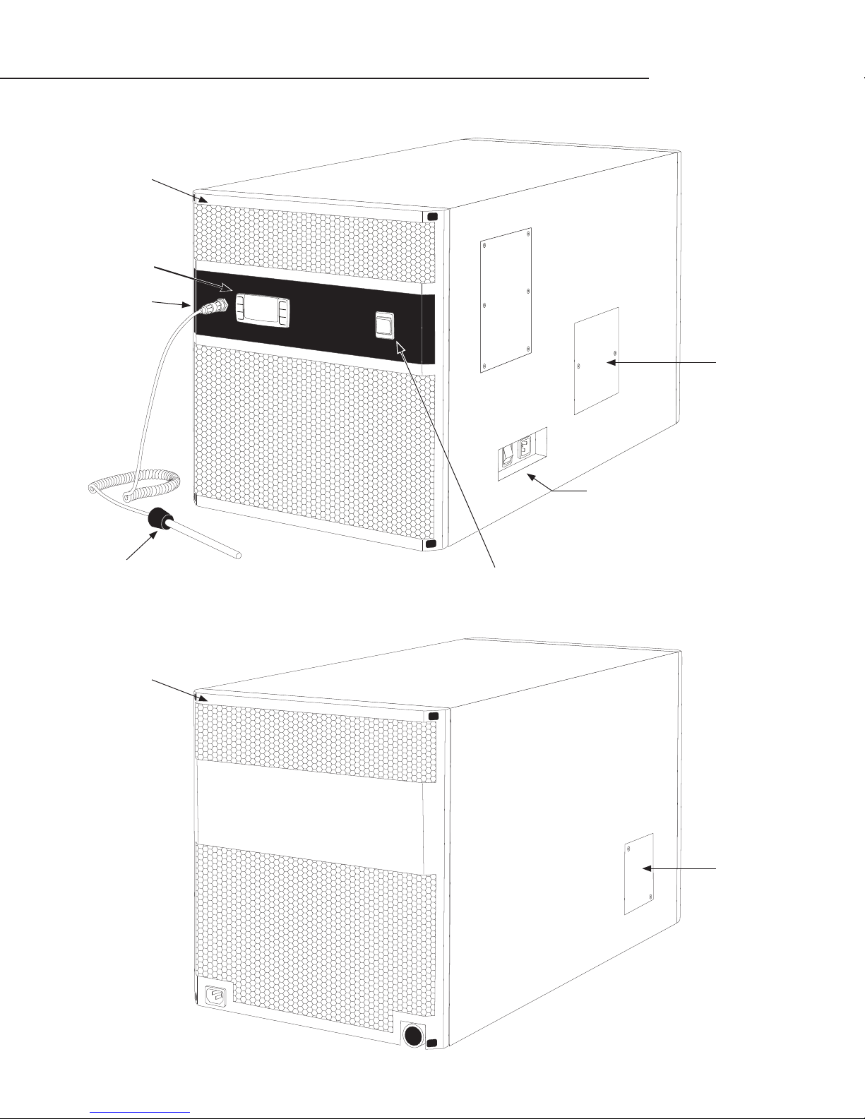
QUICK REFERENCE GUIDE
Front / Side View
Evaporator grille w/
lter
Digital controller
Bottle probe input
Ultimate Series
Compressor
access panel
Bottle probe
Rear / Side View
Evaporator grille w/
lter
Control panel
(see page 11 for details)
Fan speed control
Drain line access
Rear power inlet
Drain port
www.cellarcool.com | Page 5
Page 8
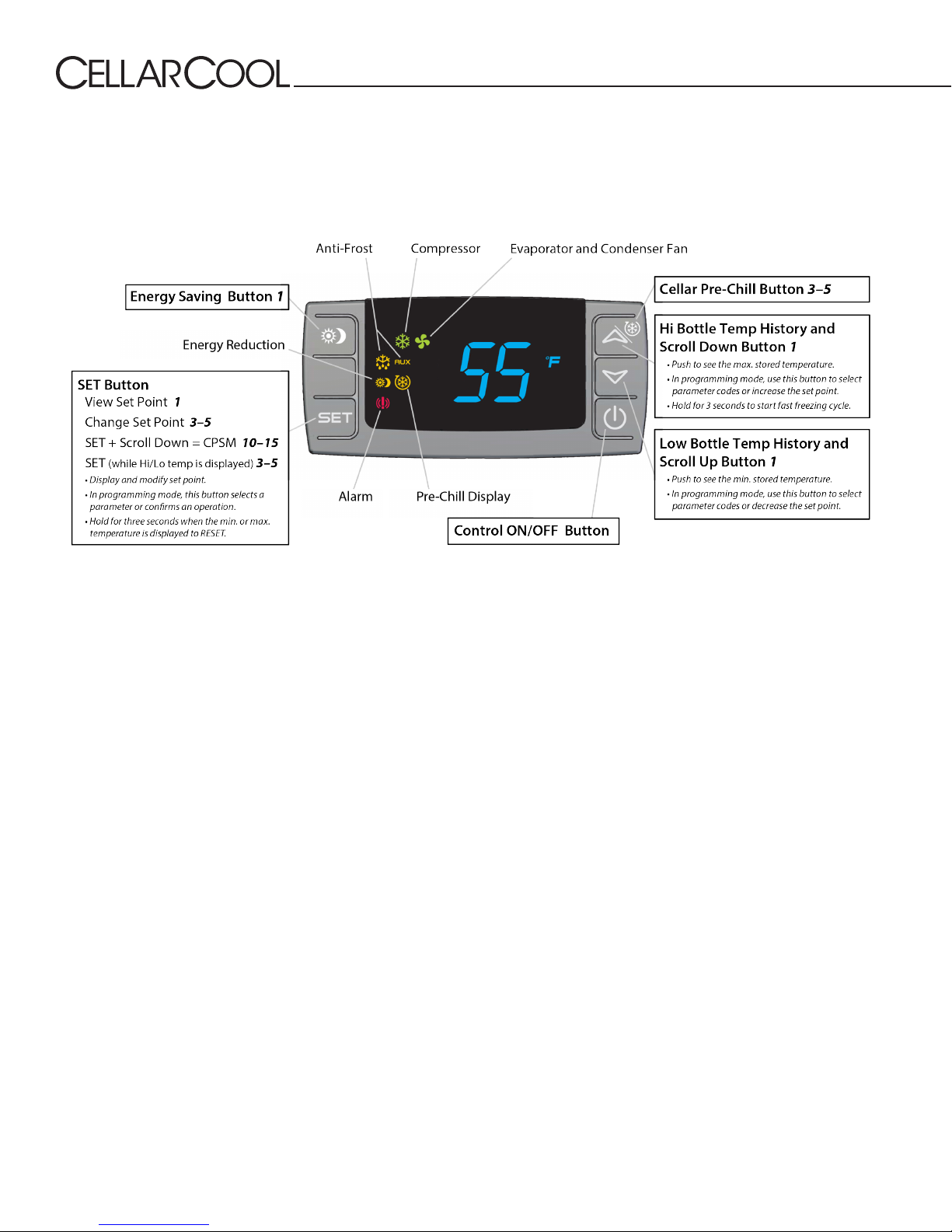
CONTROLLER LAYOUT
Note: 1 or 3–5 indicates the amount of time (in seconds) that the button must be pushed to activate the feature. Refer to page
20 for complete listing of buttons and symbols.
Page 6 | 1-855-235-5271
ULT 072517
Page 9
Ultimate Series
FAN SPEED
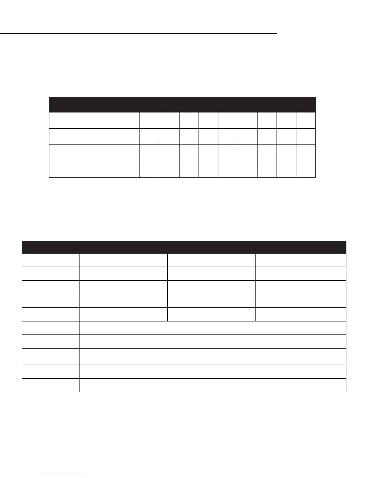
Fan speed selection is determined by the amount of heat that needs to be removed from the cellar and the type of installation
(through-the-wall or fully ducted). Fan speed selection is based on the cellar size, insulation factor, door seal, and desired wine
temperature. When initially installing the unit, set the fan speed to the High setting to quickly chill the wine cellar. Once the
wine cellar reaches the desired temperature, a lower fan speed may be selected. In the event that the outdoor temperature rises
above 90°F, (when exhausting to the outdoors) a higher fan speed may be required.
3300 4400 8800
Speed Selection
Airow (CFM)
Sound
(dBA* In Cellar / Out of Cellar)
Cooling Capacity (BTU/h)
* To give you a feeling for decibels, a food blender at 3 ft. is 90 dBA, a garbage disposal at 3 ft. is 85 dBA, a vacuum cleaner
at 10 ft. is 75 dBA, normal speech at 3 ft. is 79 dBA, a dishwasher in the next room is 55 dBA, and a quiet night is 35 dBA.
UNIT SPECIFICATIONS
Cellar Size*
Dimensions
Weight (lb.)
14.25”W x 15.75”H x 28”D 14.25”W x 15.75”H x 28”D 14.25”W x 22.25”H x 28”D
800 cu. ft. 1250 cu. ft. 2000 cu.ft
Low Med High Low Med High Low Med High
147 180 256 147 180 256 274 318 333
51/51 58/57 66/65 51/51 58/57 66/65 57/57 59/59 60/61
2374 2514 2688 3099 3453 4126 5140 5606 5760
3300 4400 8800
115 115 150
Amps (running)
dBA
Installation
Thermostat
Temp. Delta
Outside Venting
Warranty
51 low | 58 med | 66 high 51 low | 58 med | 66 high 57 low | 59 med | 61 high
Through the wall, partially ducted
Digital display
55°F temperature dierential
(maintains proper cellar temperature when exhaust environment does not exceed 110°F)
Can be done if the outside temperature does not exceed 110°F; an external grille cover is required
2 years (parts and labor) / 5 years (compressor)
9 9 10
* Sizing the Unit to the Room
The specication chart will provide information on the unit's cooling capacity. There are circumstances in which a cellar design may
require a larger unit due to preexisting design restrictions. Certain building materials such as glass, stone, or concrete may seem
adequate but do not oer the insulation capacity required to maintain the optimum temperature for storing wine. We recommend
purchasing a unit with a larger capacity to compensate for these design limitations. Undersized cooling units can lead to premature
failure and/or prevent the system from reaching the desired set temperature. As a result, they are not covered under warranty.
www.cellarcool.com | Page 7
Page 10
PREPARING THE WINE CELLAR
The performance and life of your system is contingent upon the steps you take in preparing the wine cellar. Improperly preparing your enclosure or incorrectly installing your unit may cause unit failure, leaking of condensation, and
other negative side eects.
It is highly recommended that you obtain the assistance of a wine storage professional.
Wine storage professionals work with licensed contractors, refrigeration technicians, and racking companies to build
well-insulated, beautiful, and protective wine cellars. CellarCool has put together some useful tips to assist in the
installation process. Our recommendations are meant to act as a guide in the process of building a proper enclosure.
Your intended location may have specic needs which we do not address.
Wall & Ceiling Framing
Build wine cellar walls using standard 2x4 or 2x6 boards and ceiling joists without violating local or state codes in
your area. As a general rule, the thicker the walls and the higher the insulation value, the more consistent your cellar
temperature will be.
Insulation
Insulation is REQUIRED in order to properly use CellarCool products. It is vital that all walls and ceilings be insulated
to keep the cellar temperature as consistent as possible during the summer and winter months. Standard berglass
or rigid foam insulation is normally used in cellar construction; in some cases, “blown-in” insulation is used. The
R-value, or quality of insulation, is determined by the rate at which heat passes through the insulation. The higher
the R-value, the more resistant the insulation is to conducting heat, and the more consistent your wine cellar’s
temperature will be. Using higher R-values in insulation will lower your operating costs and CellarCool unit run time.
(R-13 is the recommended minimum; R-19 is preferred for interior cellar walls, and R-30 for ceilings and exterior walls.)
Vapor Barrier
Water vapor creates its own pressure, separate from the ambient air pressure, and will intrude into colder/drier
areas. A vapor barrier is REQUIRED in order to prevent the intrusion of water vapor and maintain the correct cellar
temperature and humidity. It is recommended that 6-millimeter plastic sheeting be applied to the warm side of the
cellar walls. The vapor barrier must also be applied to the outside walls and ceiling. If it is impossible to reach the
outside, then the plastic must be applied from within the cellar. The most common method is to wrap the entire
interior, leaving the plastic loose in the stud cavity so the insulation can be placed between each stud. All of the walls
and ceiling must be wrapped in plastic for a complete vapor barrier.
In areas of high humidity, such as Southern and Gulf States, the vapor barrier will prevent inltration of warm moist
air. The moist air can cause mold to form, and standing water in drain pans promote microbial and fungal growth that
cause unpleasant odors and indoor air quality problems. If mold is found, remove it immediately and sanitize that
portion of the unit.
Note: High humidity signicantly increases the heat load on the cooling system.
Any break in the vapor barriers (cut, nail hole, over-lapping, etc.) will cause a moisture leak and must be sealed. The
electric conduit is a “duct” for vapor to travel in. The conduit should be caulked and sealed on the warm air end.
Page 8 | 1-855-235-5271
ULT 072517
Page 11
Ultimate Series
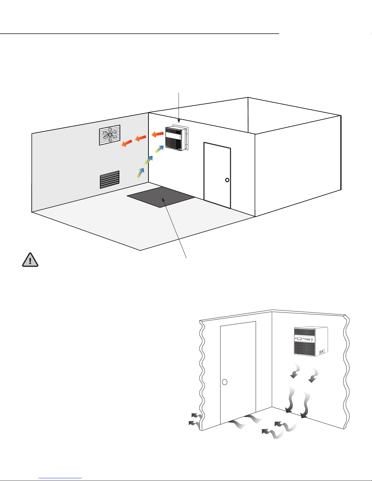
Mounting the Unit
The unit must be mounted within 18 inches of the ceiling in order to achieve sucient cooling. As the room cools down, the
warm air will rise to the ceiling. Mounting the unit high in the room will create a consistently cool environment by capturing the
warm air and replacing it with cool air. Mounting the unit low in the room will result in a temperature variation in the room due
to (a) the unit’s inability to draw warm air down from the ceiling and (b) cold air settling to the oor.
Wine Cellar
Exhaust Fan/Vent
(optional)
Air Intake
(optional)
Keep Clear
Exhaust Area
Unobstructed Airow
Unobstructed airow to and from the unit is critical for the unit’s overall performance and lifespan. Make sure there is a
minimum of three (3) feet of horizontal clearance in every direction around the unit (ve feet is ideal). The air blown by the fans
needs to circulate and either dissipate or absorb heat from the space. The system will operate more eciently with a greater
amount of air to exchange.
Note: Avoid attempting to camouage the unit. This will restrict airow, and thus the unit’s ability to work eciently.
HIGH
MED
LOW
Door and Door Seal
An exterior-grade (1¾”) door must be installed as a cellar door.
It is very important that weather stripping be attached to all
four sides of the doorjamb. A bottom “sweep” or threshold is
also required. The door must have a very good seal to keep the
cool cellar air from escaping out of the cellar. If the cellar door
does not seal properly, the unit will run continuously. In cases
where glass doors are used and the room size is close to
the recommended unit size, the next larger size CellarCool
should be used. This will compensate for the insulation loss
due to the lower insulation rating of glass.
www.cellarcool.com | Page 9
Page 12
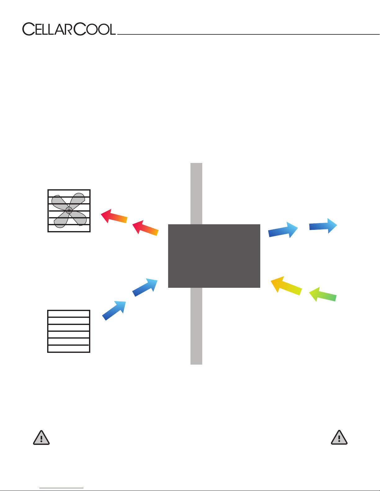
Ventilation
The necessity of dissipating heat away from the unit is critical to the unit’s performance and cannot be overstated. As the unit
operates and cools, a greater amount of heat is generated on the exhaust side of the unit. Adequate ventilation is required in
order to dissipate heat away from the unit. If ventilation is inadequate, the exhaust will heat the area or room and adversely
aect the unit’s ability to cool. In some cases, it may be advisable to install a vent fan to dissipate heat from within the exhaust
area. However, you must have a fresh air inlet as well. If your unit requires ducting, please contact CellarCool to obtain a specially
designed ducting plenum for the unit.
Using any other ducting system will void the warranty.
Note: If you are unsure whether you have adequate ventilation in your install location, please
contact us to assess your specic installation at [email protected] or 1-800-343-9463.
Back — Exhaust Room
Front — Wine Cellar
Exhaust Fan
CellarCool
(side view)
110ºF 55ºF
Air Intake Cellar Wall
Ambient Temperature Factor
The cooling unit has the ability to cool a wine cellar eciently to 55°F as long as the ambient temperature of the area that it is
exhausting to does not exceed 110°F. Therefore, you want to exhaust the unit in a room which will not exceed 110°F. Without
proper heat dissipation the unit will not have the capacity to keep the wine at a desirable 55°F.
WARNING! Allowing your unit to operate in high ambient temperatures for extended
periods of time will greatly decrease the life of your unit and void your warranty.
Page 10 | 1-855-235-5271
ULT 072517
Page 13
Ultimate Series
PREPARING THE UNIT FOR INSTALLATION
The CellarCool Unit requires a dedicated 115V, 20-amp circuit. The unit draws a large amount of amps during its initial
startup. By designating a dedicated circuit breaker, you will guarantee the unit has enough power to run eectively. Contact an
electrician for assistance with the installation of this dedicated electrical circuit.
The unit must sit upright for 24 hours prior to installation. To prepare the unit for installation:
• Remove unit from box.
• Match the electrical outlet to the plug provided on the CellarCool unit.
• Provide a dedicated circuit and wiring for the unit (see above).
• Provide a weatherproof plug for units connected outside.
Power surges and spikes can damage sensitive electrical equipment. CellarCool recommends plugging the unit into a surge
protector or power conditioner in order to protect your system. As outlined in our terms and conditions, power surges and spikes
are not covered under warranty.
We recommend that you do not use a GFI (ground fault interrupter) with this product.
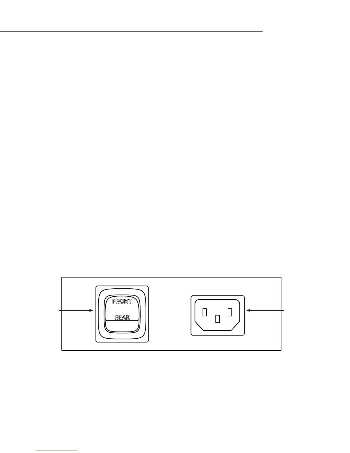
The unit is equipped with two power inlets. One is located on the right side of the unit (inside of the cellar), and the other is
located on the rear of the unit (outside of the cellar). Use the selector switch located on the right side of the unit to select which
power inlet you would like to use. If you would like to plug the unit into a socket outside of the cellar, set the selector switch to
rear. If you would like to plug the unit into a socket inside of the cellar, set the selector switch to the front position. When placed
in either position, power can only enter the unit utilizing the power inlet you’ve selected.
In case the unit should lose power, check the home/main circuit breaker. If the unit does not respond properly, refer to the
Troubleshooting Guide.
Front/Rear
Power Switch
FRONT
Power Inlet
REAR
www.cellarcool.com | Page 11
Page 14
PREPARING THE INSTALLATION LOCATION
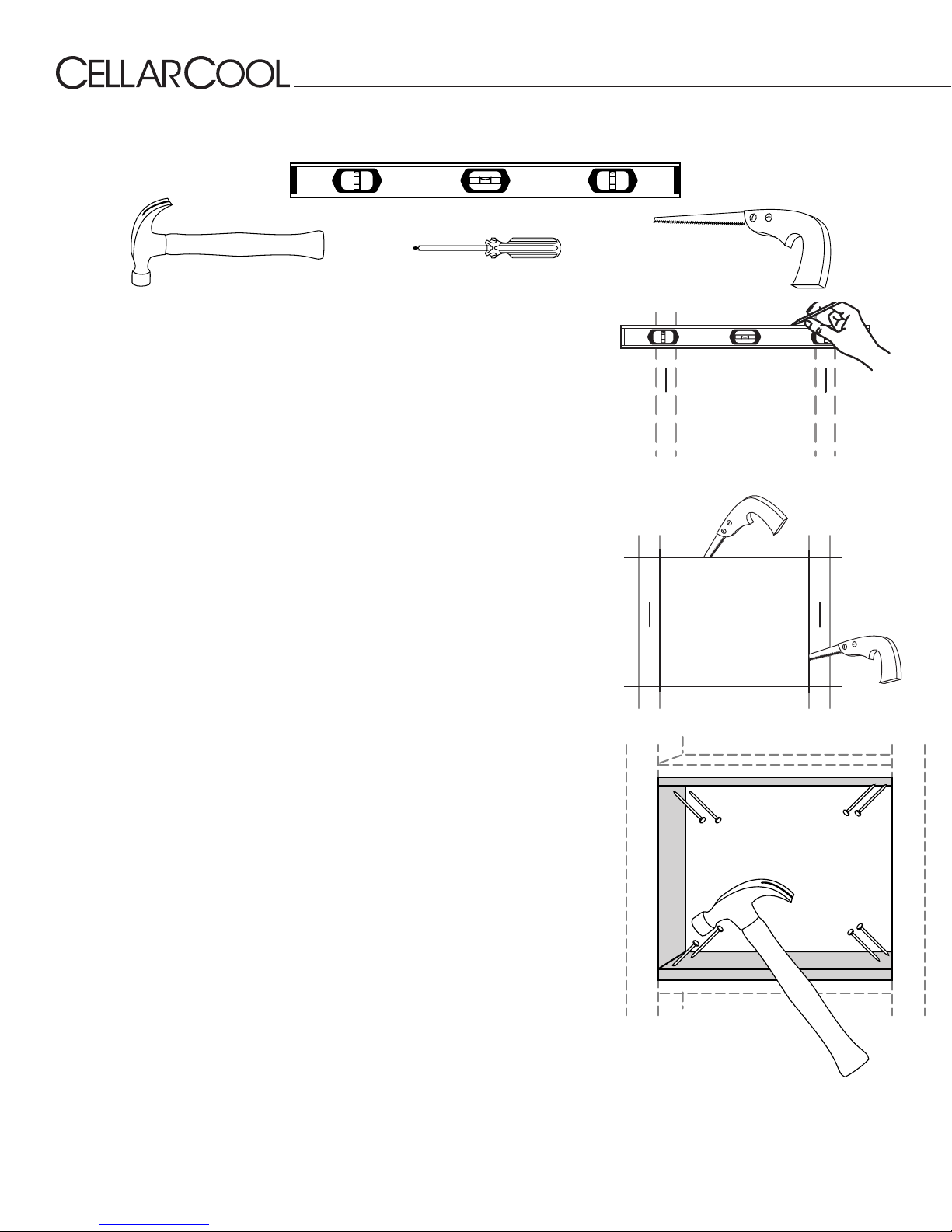
Minimum Tools Needed:
Level
Hammer SawScrewdriver
Locate the desired installation location (no more than 18 inches inches from the
ceiling). Using a stud nder, locate the studs on either side of the center point and
mark them with vertical lines.
Using a level and a pencil, mark a horizontal line on the wall between the two studs,
no less than 1½ inches and no more than 18 inches from the ceiling.
Using a ruler or measuring tape, measure 16 inches down (3300 and 4400) or 22.75
inches down (8800), and mark another horizontal line parallel to the rst one.
Using a saw, cut along the uppermost horizontal line until your saw reaches the stud.
Turn the saw around, inserting it into the cut that has just been made, and cut toward
the opposite stud so that there is a clean horizontal cut between the two studs. Be
careful not to cut into the studs themselves.
Make the second horizontal cut from stud to stud on the line 16 inches below the rst
cut.
Once the horizontal lines have been cut, make vertical cuts using the inside edge
of the studs as a guide. Once both vertical cuts have been made, there should be
rectangular hole in the sheetrock. Make the same hole on the other side of the wall.
Using a nail, mark all four corners of the rst hole by making nail holes through the
sheetrock. Connect the holes with a pencil mark and cut on the other side of the wall.
Sheetrock alone cannot support the weight of a 96-lb cooling unit. Therefore, it is
necessary to frame the hole that has just been cut with upper and lower supports.
These supports also provide solid material for the mounting bracket screws.
Using two 2x4s (14.5 inches in length) and eight 6d nails, secure the upper and lower
supports to the right and left studs, just inside the sheetrock. Make sure that the
internal height remains at 16 inches (3300 and 4400) or 22.75 inches (8800) so that the
CellarCool unit will t snugly through the framed cut-out.
Page 12 | 1-855-235-5271
ULT 072517
Page 15
Ultimate Series
SINGLE-PIECE MOUNTING BRACKET
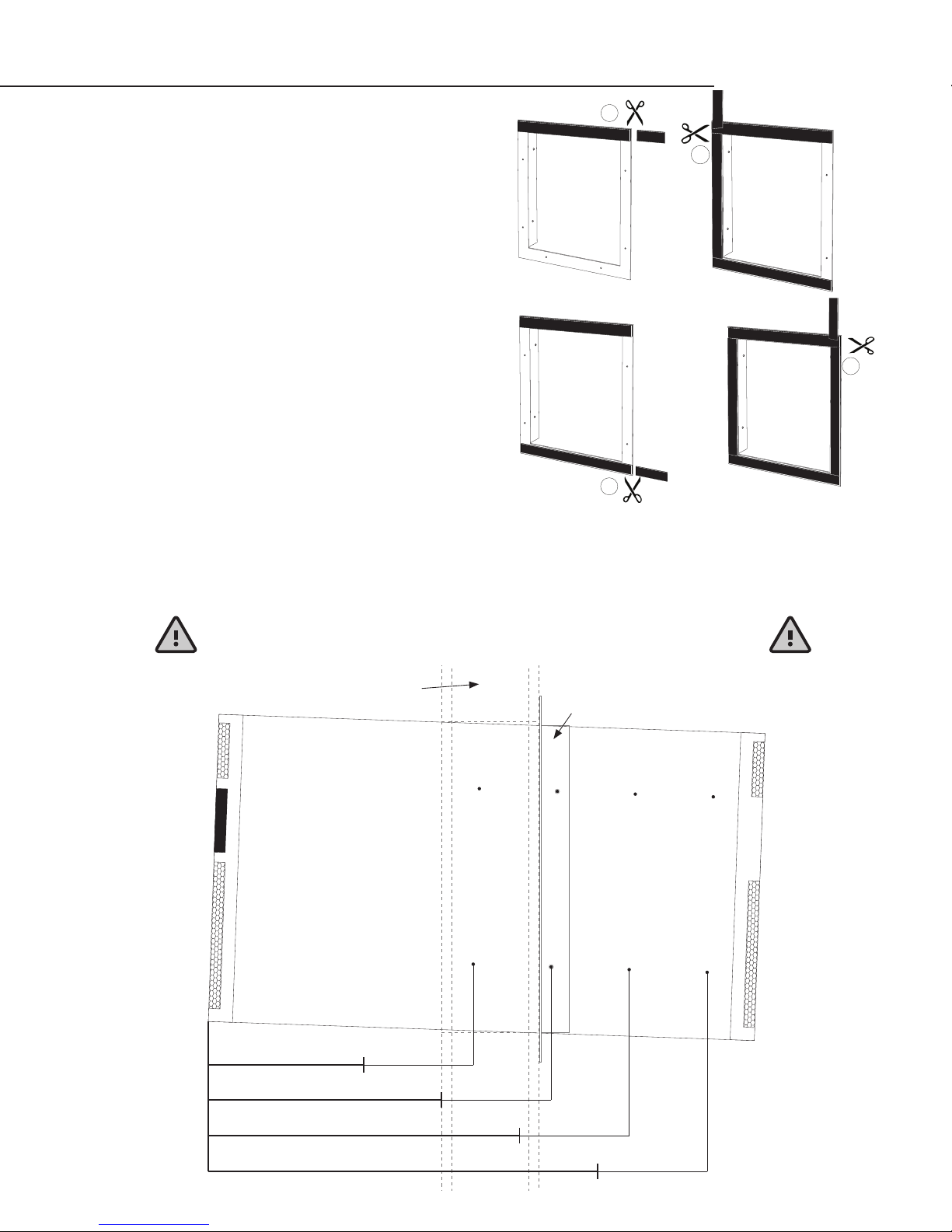
This sturdy bracket is used to frame the installation location
and secures the unit to the wall studs. The bracket has been
designed to hold the unit at a two-degree (2°) angle. This helps
project air into the space and aids in condensation drainage.
Applying Insulation Tape
Locate the six-foot piece of black foam tape included with the
unit. Align one end of the foam tape with the upper left corner
of the rear side of the mounting bracket. Stretch the tape across
the rear of the bracket and cut the tape at the opposite edge.
Peel o the white paper backing and attach the cut piece of
foam tape to the top rear side of the mounting bracket. Follow
the same procedure to place a piece of tape on the bottom edge
of the mounting bracket. Place the remaining piece of foam tape
on one side of the mounting bracket (spanning the distance
between the pieces of tape on the top and bottom edges of the
mounting bracket), then cut, remove paper backing, and secure.
Do the same with on the opposite side of the bracket. Discard
any excess. The foam tape will create a tight seal between the
bracket and the wall.
Mounting Bracket Installation
Select your desired bracket mounting location (see diagram below). This location determines the depth of the installation. For
example, position #1 keeps most of the unit out of the cellar while position #4 sets the back of the unit near ush with the
exterior wall. Slide bracket onto unit. Ensure that the TOP label on the bracket and the unit mounting anges are towards the
back. Use the four supplied ½” self-tapping screws to fasten the bracket to the unit. It is imperative that you use self-tapping
screws no longer than ½” in length.
1
3
4
2
If you are installing through an exterior wall, please review the
next page for specic instructions on exterior grill installation.
5” inch thick wall
(wall thickness m ay vary)
Wine Cellar Exhaust Area
#1 7.5–9.5” In Cellar
Mounting Bracket
#2 11.5–13.5” In Cellar
#3 15.5–17.5” In Cellar
#4 19.5–21.5” In Cellar
www.cellarcool.com | Page 13
Page 16
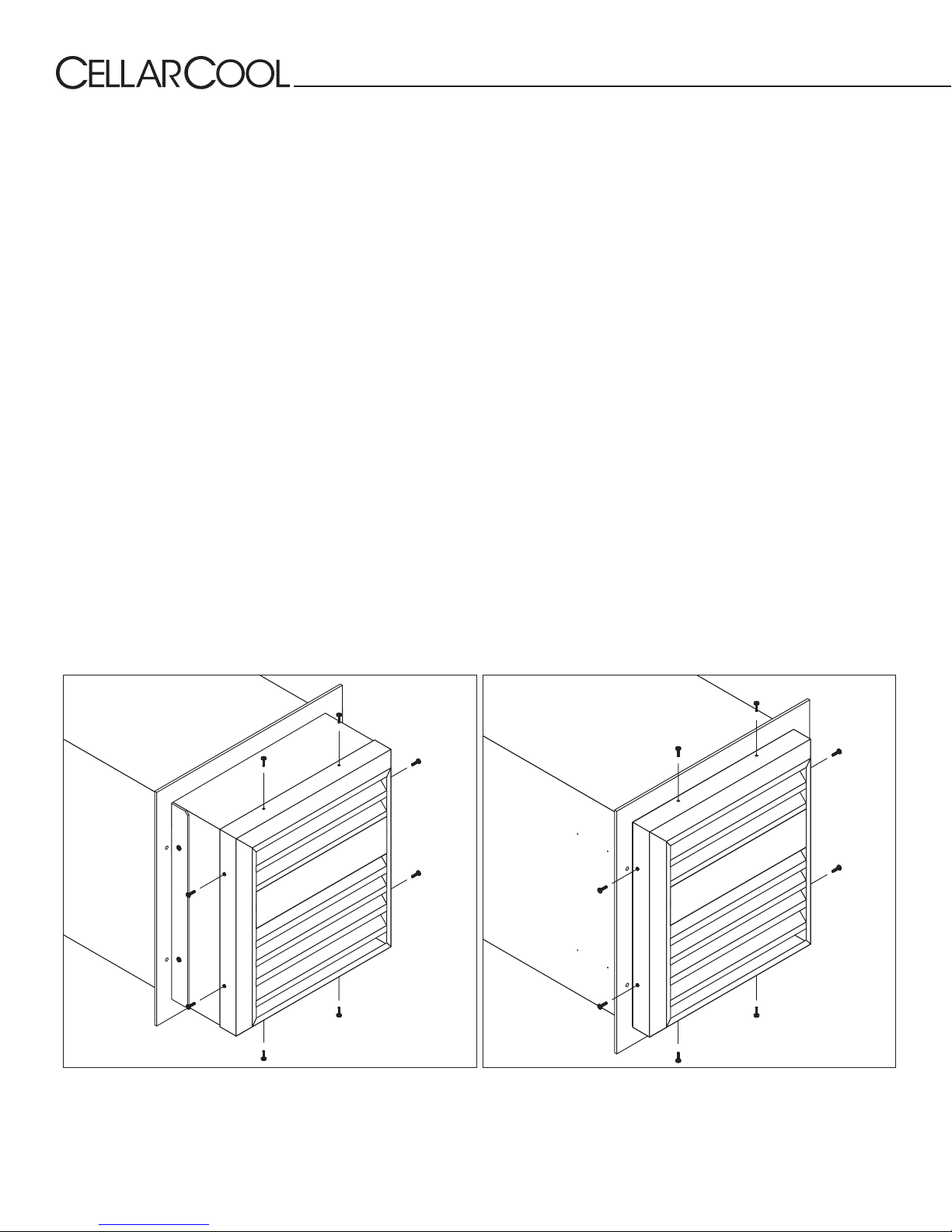
OPTIONAL EXTERIOR GRILLE
The exterior grille is required on all installations where the exhaust side of the unit is exposed to the outdoors (i.e., rain and other
adverse weather conditions).
Non-Flush Installation
Install the unit according to the standard through-the-wall procedure. After the unit is installed, place the exterior grille over the
exhaust side lter grille and line up the screw holes on the top, bottom, and sides. Use the eight (8) supplied self-tapping screws
to fasten the grille to the unit.
Flush Installation
This installation is slightly dierent because you are utilizing the same holes for both the mounting bracket and exterior grille.
1. Slide the mounting bracket onto the unit followed by the exterior grille, bring the two pieces together by sliding the exterior
grille over the mounting bracket side anges.
2. Align the two top screw holes of the exterior grill with the top screw locations on the unit, use the supplied self-tapping
screws to fasten the grille.
3. Repeat Step 2 on the bottom of the unit.
4. Use the supplied self-tapping screws to fasten the grille and bracket to the unit ensuring the bracket stays perpendicular/
square.
5. Continue through-the-wall installation.
You are required to use the ½” self-tapping screws provided. Do not drill holes into unit.
Non-Flush Installation
Page 14 | 1-855-235-5271
Flush Installation
ULT 072517
Page 17
Ultimate Series
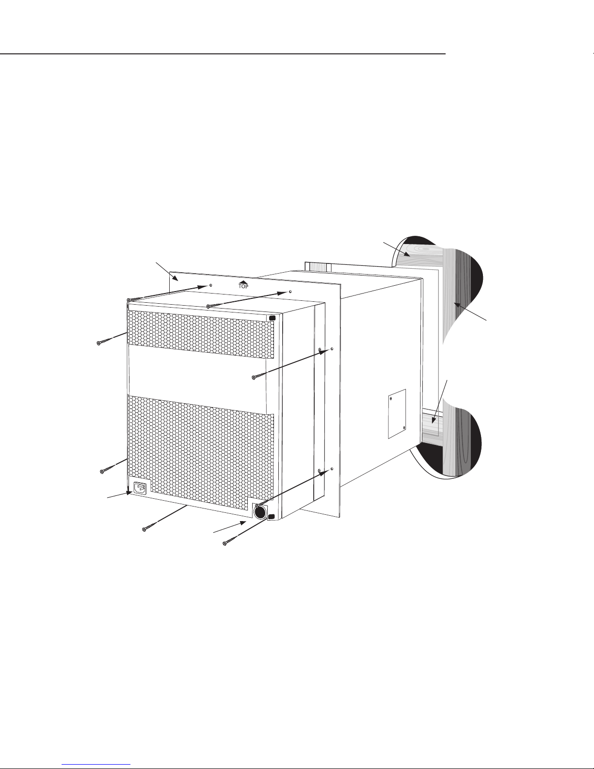
INSTALLING THE UNIT
Slide the unit from the outside wall into your wine cellar with the outer ange ush with the wall. Secure the ange to the wall
using the pre-drilled holes. The screws should penetrate the studs as well as the upper and lower supports to provide adequate
support for the CellarCool unit (see illustration). Seal all cracks and gaps around the CellarCool Ultimate unit with an air-tight sealant or caulking to prevent air leakage.
Note: If you use decorative moulding, it should be attached to the walls and never to the
cooling unit itself. The moulding itself should be removable in case the unit needs servicing.
2x4 Upper Support
Mounting Flange
Wall Stud
Rear Power
Back of Unit
2x4 Lower Support
Drain Port
www.cellarcool.com | Page 15
Page 18
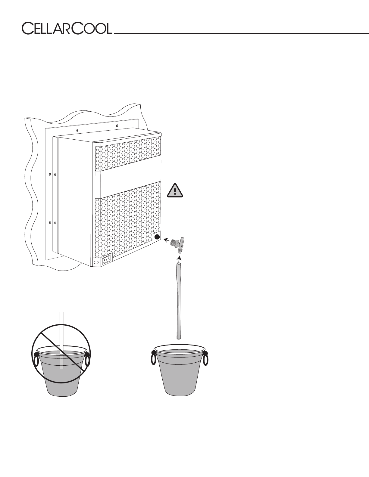
CONDENSATION DRAIN LINE
The condensation drain line tube is used to drain excess condensation from the unit to a proper discharge location. It is
important that the drain line tube be properly connected in order to prevent leakage and other problems associated with excess
condensation.
Failure to use the condensation drain line tube will void the warranty on the unit.
All units come with a drain line for additional removal of
excessive condensate. It is mandatory to install the drain line
with a “tee” tting. During operation, the cooling unit will
strip excess water from the air in order to maintain the proper
level of humidity within the cellar. However, in extreme
humidity, additional condensate will be removed. The
drain line will prevent overow and leaking by allowing for
discharge of the additional condensate.
To prevent mold from growing, allow the drain line to
hang above the water line.
Ultimate Drain Line Installation
1. Wrap tee with Teon tape one or
two turns clockwise.
WRONG: Drain line is under water.
Drain line
Black ½" tee
2. Next, thread the barbed tee into
the drain port and rotate until tight.
Make sure the barbed parts of the tee
are vertical.
3. Next, attach the piece of ½" ID clear
plastic tubing to the lower barb of
the tee.
4. Every six weeks, disconnect the
drain line from the tee. Remove the
tee from the rear drain port and clean
it. Then use the supplied drain line
brush to clean the interior drain line.
Use the drain line access door to drop
a pan tab into the drip tray to prevent
the buildup of microbial growth.
Page 16 | 1-855-235-5271
ULT 072517
Page 19
Ultimate Series
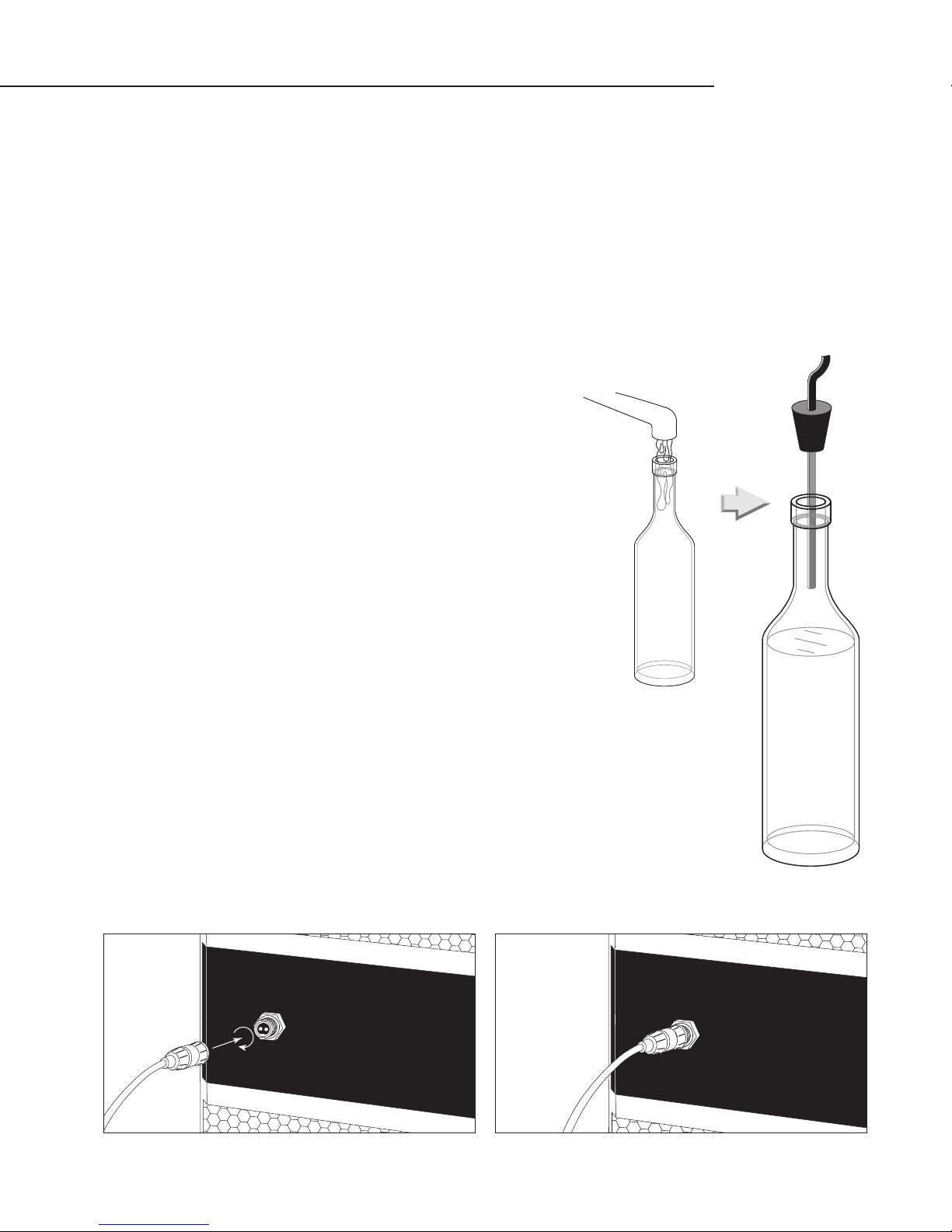
LIQUIDMEASURING THERMOSTAT SYSTEM BOTTLE PROBE
CellarCool cooling units come with a liquid-temperature-measuring thermostat. The self-calibrating bottle probe
contains a sensor which communicates back and forth with the thermostat. This results in a consistent temperature
setting and accuracy. Wine should be kept at a very precise, controlled temperature and humidity. By measuring the
liquid temperature rather than air, the unit will operate 75–80% of the time.
Setting up the Bottle Probe
1. Locate an empty wine bottle.
Figure 1
2. Fill it 75% full with room-temperature tap water.
3. Place bottle probe securely into bottle as seen in Figure 1.
4. Place bottle off to the side of the unit in your wine cellar, with the probe level.
5. To ensure a consistent temperature, place bottle probe approximately three
(3) feet away from the air output and not in the flow of the air.
6. Connect the opposite end of the bottle probe wire to the circular connector
on the front of the unit marked “bottle probe.” Twist the connector clockwise
to lock it in place as seen in Figure 2.
It is recommended that the bottle be placed in a central location of your
wine cellar. Avoid pulling too much on the probe cord. It may become
disconnected, resulting in limited functionality of the unit.
Note: The thermostat can be set between 50-67°F.
Remember: The CellarCool unit operates based on the temperature of the water.
Do not be misled by thermostats which read air temperature. The air temperature
in the cellar will be cooler than the liquid temperature of the wine while it is
reaching its optimum balanced temperature.
Figure 2
E
L
P
T
R
T
O
O
B
B
E
E
L
P
T
R
T
O
O
B
B
E
www.cellarcool.com | Page 17
Page 20
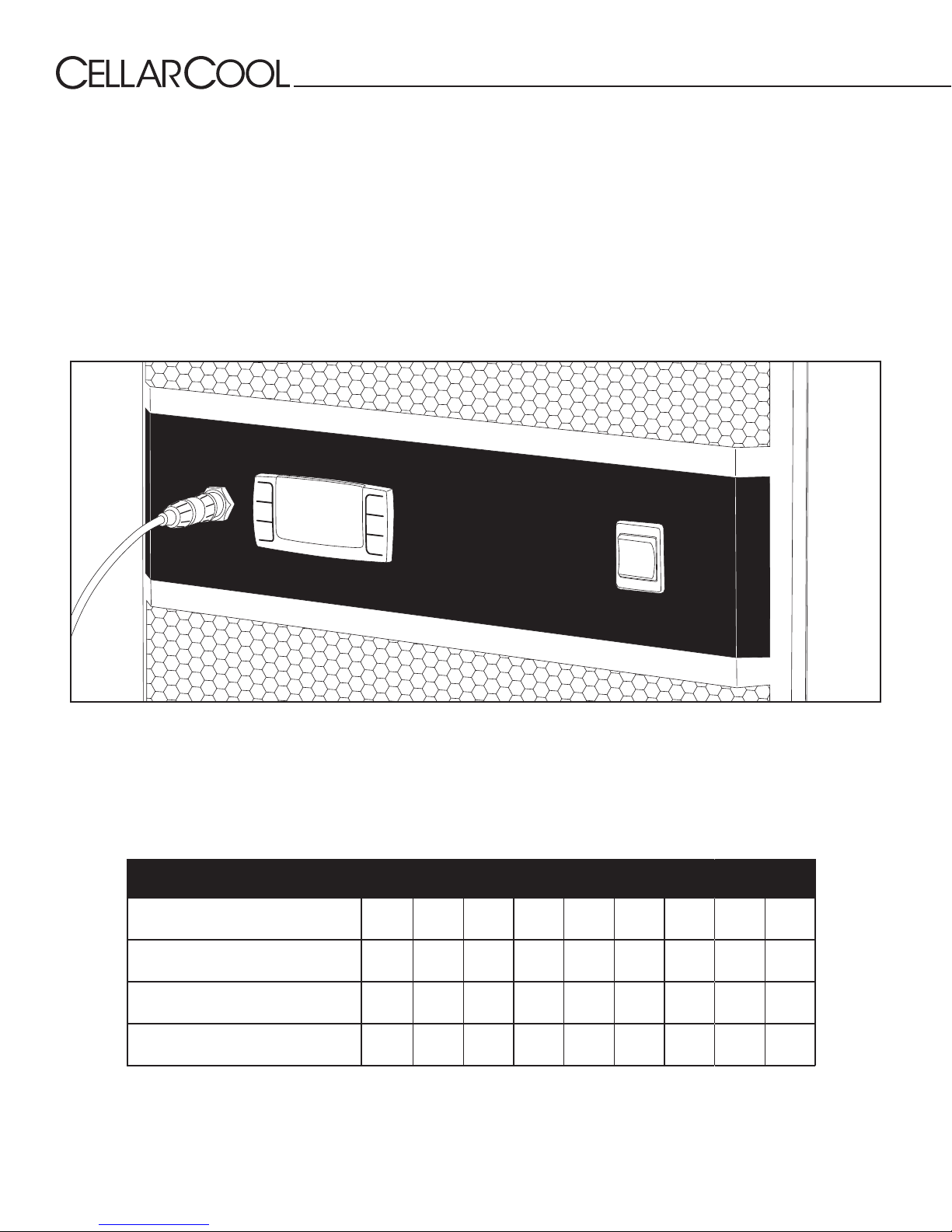
MULTISPEED FAN CONTROL
Designed for wine cellars up to 1000 and 2000 cubic feet, the Ultimate 3300, 4400, and 8800 feature multi-speed fans. These
fans have a high setting for maximum performance in high-temperature (+110°F) environments and a low setting for super-quiet
operation.
Fan Speed Selector Switch (Low/Med/High)
The cooling unit fans operate on three speed settings: Low, Medium, and High. For optimum sound and energy eciency,
select the lowest fan speed that will maintain the desired cellar temperature. If the relative humidity is low, a higher fan speed
will cause less moisture to be removed during cooling. High speed is recommended for initial cellar cool-down, extreme
temperature conditions, and ducted installations.
Fan speed selection is determined by the amount of heat that needs to be removed from the cellar and the type of installation
(through-the-wall or fully ducted). Fan speed selection is based on cellar size, insulation ratings, door seals, and the desired wine
temperature. When initially installing the unit, set the fan speed to the High setting to quickly cool down the cellar. Once the
wine cellar reaches the desired temperature, a lower fan speed may be selected. In the event that the outdoor temperature rises
above 90°F (when exhausting to the outdoors), a higher fan speed may be required.
Speed Selection
Airow (CFM)
Sound
(dBA* In Cellar / Out of Cellar)
Cooling Capacity (BTU/h)
* To give you a feeling for decibels, a food blender at 3 ft. is 90 dBA, a garbage disposal at 3 ft. is 85 dBA, a vacuum cleaner at 10 ft. is 75 dBA,
normal speech at 3 ft. is 79 dBA, a dishwasher in the next room is 55 dBA, and a quiet night is 35 dBA.
Page 18 | 1-855-235-5271
3300 4400 8800
Low Med High Low Med High Low Med High
147 180 256 147 180 256 274 318 333
51/51 58/57 66/65 51/51 58/57 66/65 57/57 59/59 60/61
2374 2514 2688 3099 3453 4126 5140 5606 5760
ULT 072517
Page 21

SYSTEM OPERATION
Ultimate Series
Initial Start-Up
When power is applied to the unit, the snowake symbol
will be displayed (if unit is calling for cooling). There may be
a delay of up to 60 seconds before the evaporator fan turns
on. When the evaporator fan is activated, the fan symbol will
display.
APST (Advance Product Safety Technology) is a temperature
control feature for the evaporator fan that comes standard
with all CellarCool units. APST ensures that in the possible
event of a cooling deciency, the heat from the indoor fan
will not raise the temperature of the wine cellar, which could
otherwise have an adverse eect on the wine-aging process.
Set Point
The set point is set at the factory (CellarCool) to 55°F. It can be
adjusted by the customer between 50–67°F in one-degree
increments.
Humidity Features
The Fon ("fan on") function is an adjustable feature which
allows the customer the convenience of reintroducing some
of the humidity removed by the fan coil during the cooling
process. When the bottle probe has reached the set point (all
units are shipped with the set point of 55°F and a dierential
of 1°), the compressor and the condenser fan will turn o, but
the indoor fan will continue to run for about 5 minutes to
reintroduce any moisture from the evaporator coil. All units
come with this feature turned o. If low humidity is a problem,
increasing "fan on" time will raise the humidity level.
Display
The bottle probe temperature is displayed by default. “Def”
is displayed during Anti-Frost. The air sensing probe and
evaporator probe temperatures can be accessed by pushing
the SET button and scrolling through “PB1” (bottle probe), and
“PB2” (evaporator probe).
Safety Features
Once the compressor relay is de-energized the controller must
wait ve minutes before reenergizing the relay. This prevents
the compressor from repeatedly turning o and on. If the unit
is calling for cooling during this time, the compressor symbol
will blink, indicating that cooling is needed but the control is
waiting for the Anti-Short Cycle delay.
In the event of a faulty bottle probe, the compressor will
cycle o for 10 minutes and on for 40 minutes. “P1” will be
displayed on the screen.
Alarms
See Alarm Codes in the Controller Functions chart on page 21.
Anti-Short Cycle
The Anti-Short Cycle ensures that the compressor will remain
o for a period of three minutes after the unit has reached
the set point to allow the pressure in the refrigeration unit to
equalize prior to starting the compressor.
Anti-Frost Cycle (defrost)
When the evaporator probe senses a temperature of 26°F
for ve minutes, the unit will go into an Anti-Frost Cycle. This
will shut down the compressor and allow the evaporator and
condenser fans to run to evaporate any frost accumulation on
the coil. The compressor will remain o until the evaporator
coil reaches 40°F, or for a maximum of ten minutes. The unit
will then return to normal operation.
Bottle Probe Failure Protection
In the event that a bottle probe should fail, the APST (Advance
Product Safety Technology) will automatically transition
the compressor to a pre-determined time cycle (based
on detailed laboratory testing), which will ensure that the
product is kept within a safe temperature range.
www.cellarcool.com | Page 19
Page 22
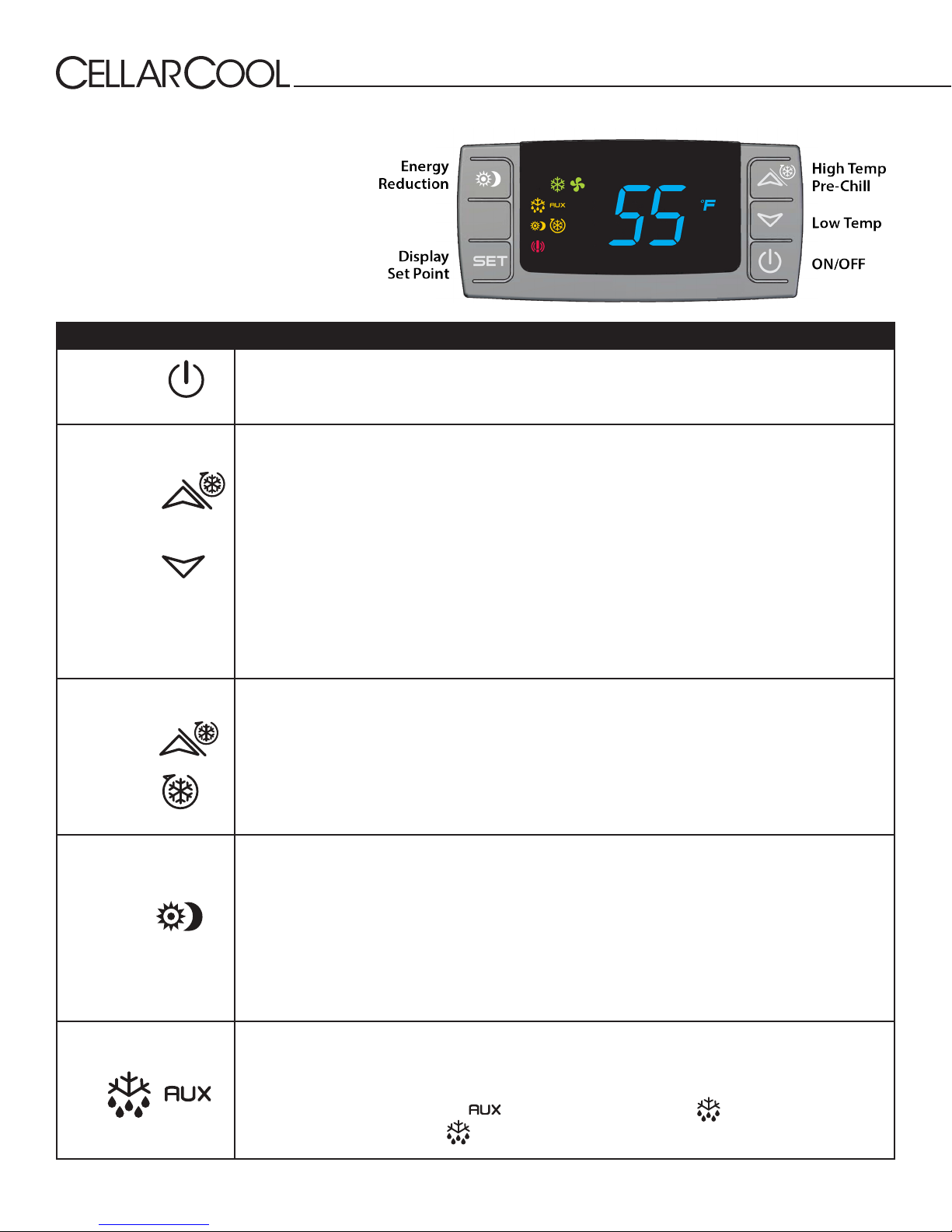
STANDARD
CONTROLLER
FUNCTIONS
If your unit is installed through the wall and
does not have a remote controller, you have the
standard controller.
Button/Symbol Normal Functions
ON/OFF
The ON/OFF button allows the customer the convenience of turning the refrigeration unit ON or
OFF from the control panel. This feature does not disconnect power from the unit. In order for the
power to be shut o from the unit, the power cord must be unplugged from the wall outlet.
UP/DOWN ARROWS
CELLAR PRE-CHILL
(CPC)
ENERGY REDUCTION
(ER)
Use these buttons to scroll through the CPSM (Customer Preference Selection Mode) menu. The
arrow buttons also display the highest and lowest temperatures sensed by the bottle probe. They
can be easily reset to reect current temperatures.
1. Press the UP ARROW or DOWN ARROW button once and the highest or lowest temperature (Hi/
Lo) sensed by the bottle probe will be displayed.
2. To reset the Hi/Lo, press and hold the SET button when the Hi/Lo value is displayed on the
display, continue to hold the SET button until “rSt” appears on the display and then blinks. This
will erase the past recorded temperature data history and start recording from the current time
and temperature.
3. The Hi/Lo feature should be reset at initial startup and after the cellar or cabinet has reached its
normal operating temperatures, generally 55°F.
Activate the CPC feature by pressing the UP ARROW button for 3–5 seconds until the CPC logo
appears on the display. The CPC feature can be terminated by pressing the UP ARROW button for
3–5 seconds. The feature will self-terminate after six hours.
The CPC feature may be used to pre-chill the cellar prior to loading it with warm product. The
feature will shift the set point down to a lower setting of 52°F, for the next 6 hours. After the sixhour time period, the set point will automatically return to the original set point.
The CPC feature can be conveniently adjusted to the customer’s specic needs, by accessing the
CPSM (Customer Preference Select Mode). See CPSM Instructions on the following page.
The ER feature is activated by pressing the ER button once. The ER symbol (a sun and a crescent
moon) will appear on the display. The ER feature reduces energy consumption by shifting the set
point up by four degrees. This allows cooling unit to run for shorter periods of time, resulting in a
reduction in energy cost. The ER feature allows for energy savings at any time — during periods of
high ambient temperatures, vacations or business travel.
To deactivate the ER feature, press the ER button one time, and the ER logo will turn o. The ER
feature can be conveniently adjusted to the customer’s specic needs. See CPSM Instructions on
the following page.
ANTI-FROST CYCLE
Page 20 | 1-855-235-5271
The Anti-Frost Cycle is automatically activated when the evaporator registers a temperature of 25°F
for a period of ve minutes. During this cycle the compressor and condenser fans will turn o while
the evaporator fans continue to run. Once the temperature of the evaporator gets back up to 40°F
the cycle will deactivate and the unit will revert back to normal operating conditions.
At the beginning of the cycle the symbol will display and the
the cycle begins properly, the symbol will be steadily illuminated.
symbol will ash. When
ULT 072517
Page 23
Button/Symbol Normal Functions
Ultimate Series
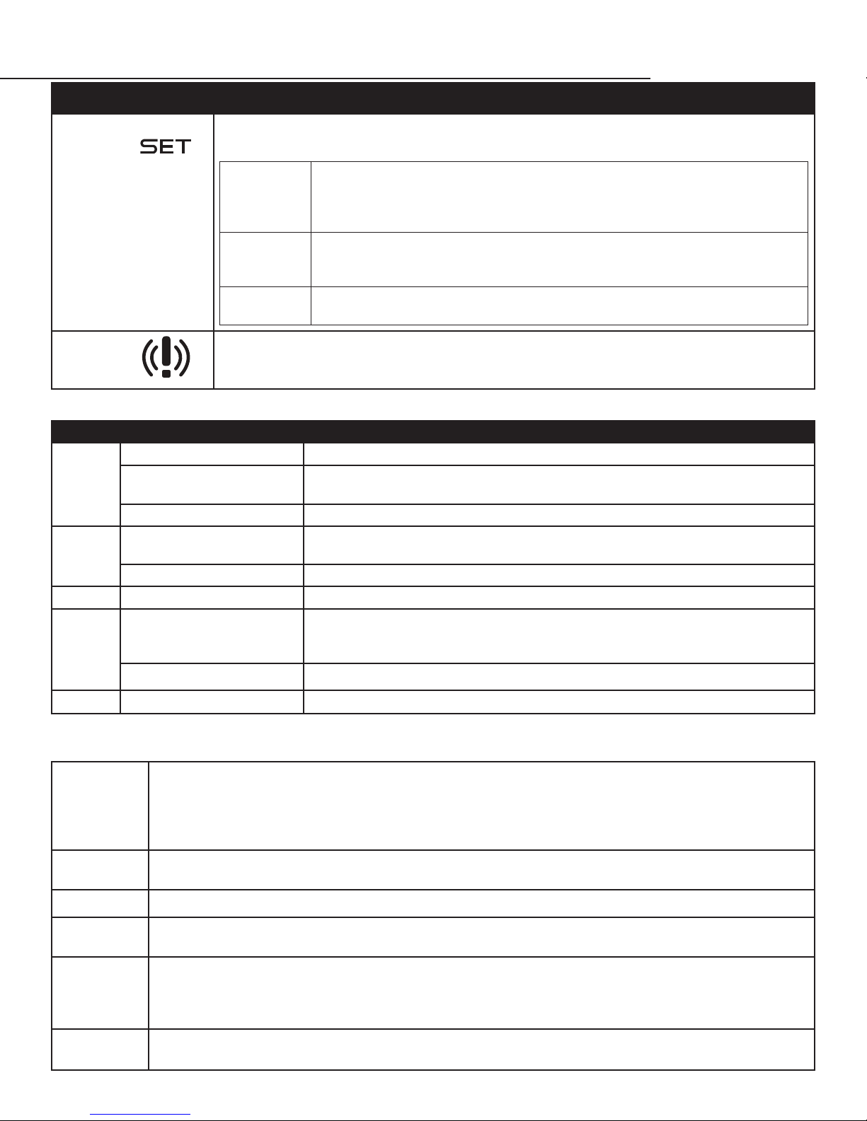
SET BUTTON
ALARM
Press the SET button once and it will display the set point. After approximately 5 seconds, the
display will return to normal operation and display the bottle probe temperature.
Press and hold the SET button for 3–5 seconds until the set point is displayed and
Change
Set Point
Reset
Temp.
History
CPSM
The Alarm symbol is shown when the unit encounters an issue that needs attention, the displayed
alarm codes are explained below.
the °F symbol blinks. Press the UP or DOWN ARROW buttons to select a new set
point. Press the SET button once and the set point numbers and the °F on the
display will blink to conrm the new setting.
Press and hold the SET button during the display of the Hi/Lo (temperature data
history). Hold button until “rSt” blinks on display, erasing the current time and
temperature data.
Press the SET and the DOWN ARROW buttons simultaneously for 10–15 seconds
to enter CPSM (Customer Preference Selection Mode).
ALARM CODES
Message Cause Solution
Bottle probe is unplugged Attach bottle probe to unit
“P1”
“P2”
“HA”
“L A”
Faulty bottle probe
connection
Defective bottle probe Replace the bottle probe
Faulty evaporator probe
connection
Defective evaporator probe Replace the evaporator probe
Defective bottle probe Replace the bottle probe
The bottle probe is sensing
a temperature that is 4°
below the set point
Defective bottle probe Replace the bottle probe
1. Check bottle probe attachment at circular connector
2. Check bottle probe connection at the back of controller
Check evaporator probe connection at green terminal block on the back of
controller
Allow the room to warm up which will increase the temperature of the wine
“POF”
The controller is locked Hold UP and DOWN ARROW buttons for 3–5 seconds to disable. “PON” will display.
CPSM (CUSTOMER PREFERENCE SELECTION MODE)
Press and hold the SET and DOWN ARROW buttons for 10–15 seconds to enter the CPSM menu.
Fon
Humidity
Management/
Enhancement
FOF
CCS
Con/Cof
HES
The "fan on" setting is preset at the factory to zero minutes, which should provide adequate relative
humidity for the cellar. Increasing the amount of "fan on" time will increase the Humidity Enhancement
(%RH). Adjustments should be made in increments of 5, with a maximum of 15 and a minimum of 0. After
any adjustment to Humidity Enhancement, you should wait a minimum of three days before making any
additional adjustments. This will allow the cellar sucient time to acclimate to the new setting.
The "fan o" time is normally set to 15 minutes. This parameter should not be adjusted, as it simply provides
an OFF cycle time for the fan during the compressor's OFF cycle.
Cellar Pre-Chill Set Point. This parameter is set at 52°F, but can be adjusted to a set point between 50–67°F.
Cellar Pre-Chill Duration. This parameter is set to 6 hours, but can be adjusted to a set point between 0–23.5
CCt
hours.
Compressor On time (Con) and O time (Cof) with a P1 Alarm. These parameters are set at Con 40 min/Cof 10 min.
In the event of a P1 Alarm, the compressor/refrigeration system automatically starts a predetermined ON/OFF
cycle, which is controlled by the Con and Cof parameters. These parameters can be adjusted to maintain the
desired bottle temperature.
Dierential for Energy Reduction. During the Energy Reduction mode, this parameter is set at 4°F above the set
point. A decrease in this setting will lower the set point and an increase in this feature will raise the set point.
www.cellarcool.com | Page 21
Page 24
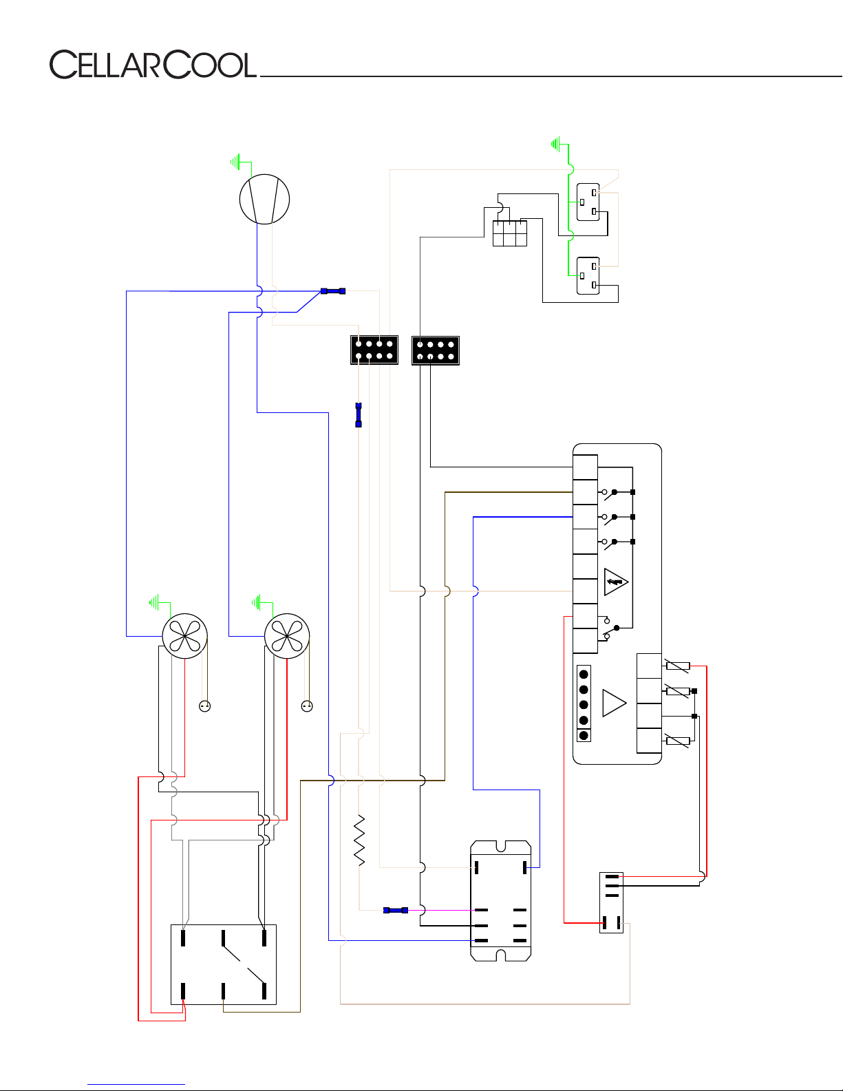
ULTIMATE 3300, 4400, & 8800 WIRING DIAGRAM
blue
Condenser
Fan
blue
blue
white
Evaporator
Fan
Compressor
white
white
white
white
black
black
6
3
5
4
2
1
FRONT/REAR SWITCH
black
line
fan
comp
neutral
white
1 2 3 4
5
6 7 8
black
white
16A
16(5)A
Receptacle
Front
Receptacle
Rear
Max
5A 250V~
8(3)A 250V~
black
grey
6 3
white
red
Med
Low
brown
Capacitor
4 1
High
black
grey
5
2
white
red
Fan Speed
Switch
brown
Capacitor
crankcase heater
brown
white
purple
black
blue
8(3)A 250V~
D.I.
9 10
!
11 12
Evap.
Room
blue
red
1 5
Anti-Frost
red
black
0
3 4 2
Relay
NC C NO
7 8 6
3
4
2
Relay
Compressor
1
Page 22 | 1-855-235-5271
ULT 072517
Page 25

NOTES
Ultimate Series
www.cellarcool.com | Page 23
Page 26
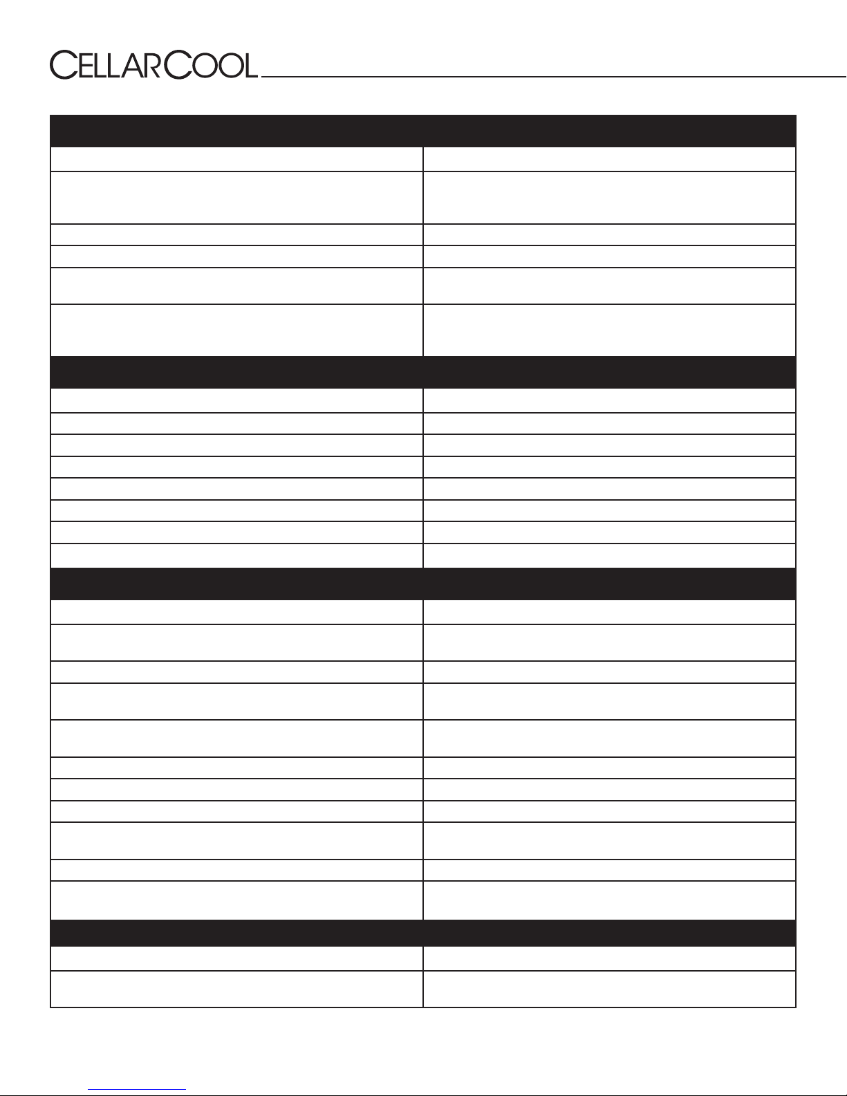
TROUBLESHOOTING GUIDE
Unit has ice forming on the evaporator
Possible cause Solution
Evaporator coil is dirty Clean the coil with a vacuum. If coil is very dirty, use a spray bottle
with a small amount of liquid dish detergent or coil cleaner. Spray coil,
let set for ve minutes, then ush with fresh water.
There is something blocking the supply and/or return air Remove blockage
The evaporator fan is not turning on Call a service tech to troubleshoot
The unit has not gone through an Anti-Frost Cycle yet Check the coil for surface ice. Melt with blow drier until coil is warm to
the touch. Soak up water with a towel.
The unit continues to ice Observe ice formation pattern. If only part way up the coil face, unit
could be low on refrigerant. If all the way up, the coil may be dirty or
airow is blocked.
Unit does not run/power up
Possible cause Solution
Unit is not plugged in Make sure the unit is plugged into an outlet
Power switch not on Turn unit on by pressing the power button on the control
Line voltage is incorrect rating for unit Check line voltage to make sure there is 110V-120V
Bottle at set point Lower set point
Thermostat not calling for cooling Lower set point
Power select switch in wrong position See page 11 for correct switch position
Faulty thermostat or wiring Call Customer Service at 1-800-343-9463
Cellar temperature is too warm
Possible cause Solution
The temperature of the room to which the unit
exhausts exceeds 110°F
The unit is undersized for the cellar Order correct size unit
There is something blocking the supply and/or return air on
evaporator or condenser side of the unit
Unit is mounted too low in the cellar Relocate unit so the distance from the ceiling and top of the unit or
One or more of the fans is not turning on Call Customer Service at 1-800-343-9463
Compressor is not turning on Call Customer Service at 1-800-343-9463
Compressor keeps cycling on overload Make sure all fans are working and there is no airow obstruction
Poor seal around door Make sure there are no air gaps around the door. If door seal is
Set point too high Lower the set point
Evaporator coil is frosted or iced up Observe ice formation pattern. If only part way up the coil face, unit could
Intake temperature needs to drop below 110°F
Remove airow obstruction
cold air supply duct is no more than 18”
damaged, replace it.
be low on refrigerant. If so, call Customer Service at 1-800-343-9463.
System runs constantly
Possible cause Solution
Leaky door seal or poorly insulated cellar Fix leaky door seal and insulate cellar in accordance with this manual
(page 9)
Page 24 | 1-855-235-5271
ULT 072517
Page 27
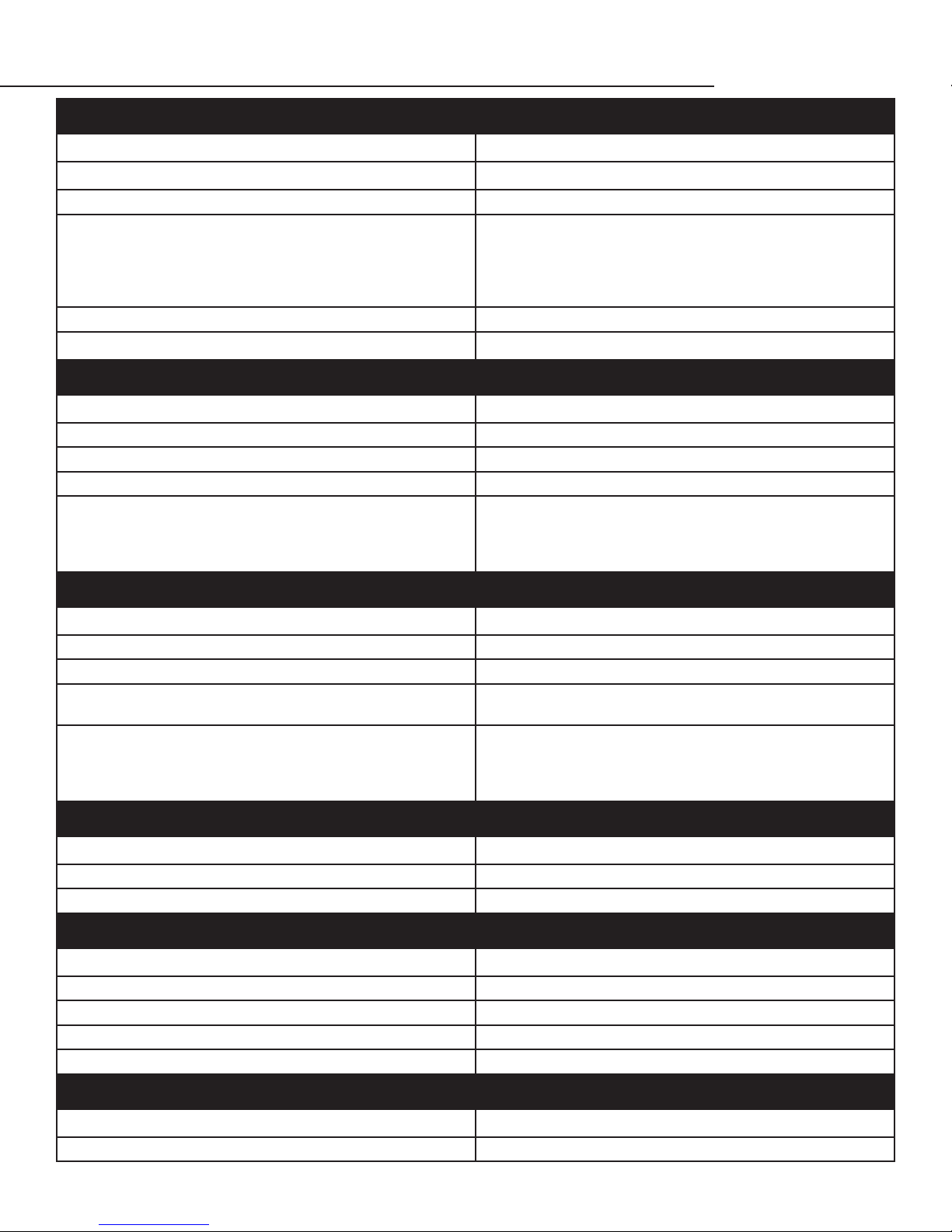
Ultimate Series
Unit leaks water
Possible cause Solution
Unit is level
Drain line clogged or kinked Check drain line to make sure water can ow freely
Drain is clogged, preventing water form escaping 1. Disconnect exterior drain line and clear it out; run provided drain
Drain line does not have a downward slope Fix drain line so there is a downward slope from the unit to the drain
Coil is iced, causing drain pan to freeze and water to overow Melt ice with blow drier; soak up with a towel
Unit runs but does not cool
Possible cause Solution
Lack of airow Make sure fan is unobstructed and coil is clean
Compressor not running Call Customer Service at 1-800-343-9463
Unit undersized Call Customer Service at 1-800-343-9463
Compressor is overheating Shut unit o for 1 hour to allow compressor to cool. Turn back on
System should have a two-degree (2°) pitch towards the exhaust side
line brush through the drain port and into the interior drain line.
2. Open access door and, using a ashlight, check drain line for
blockage; drop a pan tab into the drain pan to prevent further
blockages.
and check for cooler air to ow out. If compressor runs, check for and
clean condenser coil as a possible cause of compressor overheating.
If problem repeats, call Customer Service at 1-800-343-9463.
Evaporator fan runs but compressor does not
Possible cause Solution
Running an Anti-Frost cycle Check evaporator coil temperature
Compressor and/or starting components faulty Call Customer Service at 1-800-343-9463
"Fan on" (FOn) setting has been increased, allowing fans to run after
the compressor turns o
Compressor may have overheated Shut unit o for 1 hour to allow compressor to cool. Turn back on
Lower the "fan on" (FOn) time
and check for cooler air to ow out. If compressor runs, check for and
clean condenser coil as a possible cause of compressor overheating.
If problem repeats, call Customer Service at 1-800-343-9463.
Compressor runs but evaporator fan does not
Possible cause Solution
Faulty fan motor Call Customer Service at 1-800-343-9463
Faulty controller Call Customer Service at 1-800-343-9463
Compressor short cycles
Possible cause Solution
Evaporator blows on bottle probe Move bottle probe to a more central location
Unit low on refrigerant charge Call Customer Service at 1-800-343-9463
Condensing fan motor/capacitor faulty Call Customer Service at 1-800-343-9463
Compressor and/or starting components faulty Call Customer Service at 1-800-343-9463
Humidity in cellar too low
Possible cause Solution
Not enough moisture Install a humidier or decorative fountain in the wine cellar
www.cellarcool.com | Page 25
Page 28
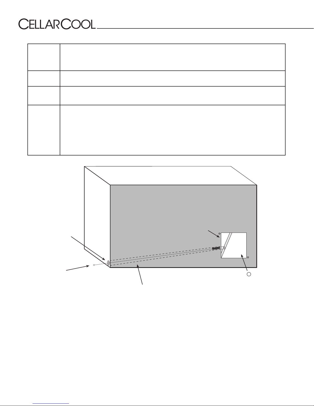
MAINTENANCE SCHEDULE
Monthly
Every Six
Weeks
Quarterly
Annually
1. Check lters
2. Check for unusual noise or vibration
3. Check drain line to see if it is above the waterline (when draining into a vessel)
Using the supplied drain line brush, clean the interior drain line leading from the drip tray and drop a
pan tab into the drip tray (see illustration below for more details).
1. Clean lters
2. Replace lters on ducted units (see diagram below)
1. Replace lters if worn or plugged beyond cleaning
2. Use a vacuum with brush attachment to clean coils; be careful not to crush coil ns
3. Inspect for corrosion
4. Check wiring connections and integrity of cords
5. Examine duct work for cracks or possible leaks
6. Pour a 50/50 bleach solution into the drain line every spring
TOP OF UNIT
EXTERIOR UNIT HOUSING
REAR
OF
UNIT
ACCESS DOOR
EXTERIOR DRAIN PORT
Insert supplied drain
line brush from this
end
INTERIOR DRAIN LINE
DRIP
TR AY
Drop pan tab into drip tray
through access door
Pan tabs kill bacteria and related odors, remove sludge and scale, and help to prevent water damage caused by condensate overow. They are non-corrosive and easy to install. Simply use the access door to drop a pan tab into the drip
tray every six weeks.
WARNING: Keep pan tabs out of reach of children. They contain quaternary ammonium chloride and
can cause skin and eye irritation. They are harmful or fatal if ingested. Wear protective gloves when
handling pan tabs. Wash hands thoroughly after handling. If pan tabs make contact with eyes, rinse
cautiously with water for several minutes. In case of an emergency, call 1-800-255-3924 (24 hours).
Page 26 | 1-855-235-5271
ULT 072517
Page 29

Ultimate Series
TECHNICAL ASSISTANCE
CellarCool Customer Service is available Monday through Friday from 6:00 a.m. to 4:00 p.m. Pacic Standard Time.
The appointed customer service representative will be able to assist you with your questions and warranty information more
eectively if you provide them with the following:
• The model and serial number of your CellarCool system(s).
• Location of unit and installation details, such as ventilation, ducting, construction of your wine cellar, and room size.
• Photos of the cellar and installation location may be needed.
Contact CellarCool Customer Service
1738 E. Alpine Ave
Stockton, CA, 95205
www.cellarcool.com
Email: [email protected]
Technical Support & Customer Service: 1-800-343-9463
Sales & Sizing Assistance: 1-855-235-5271
Fax: 209-466-4606
ACCESSORIES FOR COOLING UNITS
CellarCool oers accessories to enhance and customize your wine cooling unit.
Exterior Grille
Protects the unit from the weather elements when placed on the exhaust side.
• Small Exterior Grille (used for Ultimate 3300 and 4400)
• Large Exterior Grille (used for Ultimate 8800)
Condensate Pump Kit
The condensate pump kit is designed as an automatic condensate removal pump for water dripping out of our cooling units’
drain line. The pump is controlled by a oat/switch mechanism that turns the pump on when approximately 2¼” of water
collects in the tank, and automatically switches o when the tank drains to approximately 1¼”. The condensate pump kit allows
the excess condensate to be pumped up to 20 feet away from the unit.
Ultimate Ducting Kit
This kit allows either side of the unit to be ducted. Duct the cold air through a vent into the cellar, duct the hot exhaust air out of
the home. This option allows for total installation exibility.
Note: Flex or rigid ductwork is not included.
Accessories can be purchased at www.cellarcool.com
www.cellarcool.com | Page 27
Page 30
Ultimate Series
Product Warranty Information
CellarCool Product Terms and Conditions
Including Product Limited Warranty And Product Installation Requirements
For CellarCool Ultimate Series
ATTENTION: PLEASE READ THESE TERMS OF USE CAREFULLY BEFORE INSTALLING YOUR CELLARCOOL COOLING
SYSTEM. INSTALLING YOUR CELLARCOOL COOLING SYSTEM INDICATES THAT YOU ACCEPT AND AGREE TO EACH OF
THE TERMS AND CONDITIONS SET FORTH HEREIN (“TERMS OF USE”). IF YOU DO NOT ACCEPT THESE TERMS OF USE,
YOU RISK VOIDING YOUR WARRANTY AND ASSUMING ADDITIONAL REPAIR AND REPLACEMENT COSTS.
1. Purchase of a CellarCool Cooling System assumes that the Purchaser (“End User”) fully accepts and agrees
to the Terms and Conditions set forth in this document. The Terms and Conditions of Sale and Owner’s Manual
are shipped with each unit and, if another copy is needed, replacement copies can be downloaded from the
company website (cellarcool.com) or by contacting CellarCool directly for a new copy. CellarCool reserves the
right, in its sole discretion, to change its Terms and Conditions at any time, for any reason, without notice.
2. CellarCool Product Limited Warranty:
A. Two (2) Year Limited Warranty. For the period of TWO (2) YEARS (the “Limited Warranty Period”) from the date of
original sale of a Product by CellarCool, if a CellarCool Product is found to be defective in material or workmanship
after undergoing CellarCool’s customer service troubleshooting, then, subject to the CellarCool Product Limited
Warranty Limitations and Exclusions as well as the other Terms and Conditions stated herein, CellarCool will do the
following, as appropriate, for the end user (“End User”) who has installed and is actually using the Product, with
regard to LABOR, PARTS and FREIGHT:
1. LABOR - repair or replace (at CellarCool’s sole option) the Product. If CellarCool determines that Product is
to be REPLACED, there will be no labor reimbursement. If CellarCool chooses to REPAIR the Product, CellarCool
will consider possibility of maximum reimbursement of $350.00 in labor for REPAIRING Product on site and
supplying all parts at no charge. Invoice for service must be forwarded to CellarCool for assessment and
processing.
2. PARTS – supply, at no charge, new or rebuilt replacement parts for the Product in exchange for the return of
defective parts. CellarCool, at its option, will assess possibility to replace unit that is at the original site with a
warranty replacement unit OR consider possibility of supplying all parts at no charge.
3. FREIGHT – cover normal ground freight charges for parts, and, in the event the Product is not repairable
in the eld, CellarCool, at its option, will pay freight charges to return original Product to CellarCool for
evaluation. End User is responsible for freight charges of replacement Product being shipped to End User.
B. Five (5) Year Compressor Limited Warranty. CellarCool Product’s compressor only will be covered for ve (5) years
from date of purchase. Labor and freight of compressor is the End Users responsibility.
C. Product Warranty Limitations and Exclusions:
1. This limited warranty does not cover cosmetic damage caused during installation, damage due to acts
of God, commercial use, accident, misuse, abuse, negligence, or modication to any part of the Product.
Delivery and installation of the Product, any additional parts required, as well as removal of the Product if
warranty work is required, are all at the sole cost, risk and obligation of the End User.
2. This limited warranty does not cover damage due to improper installation or operation or lack of proper
maintenance of the Product, connection of the Product to improper voltage supply, or attempted repair of
the Product by anyone other than a technician approved by CellarCool to service the Product.
3. This limited warranty does not cover any Product sold “AS IS” or “WITH ALL FAULTS.”
4. Product that has been replaced during warranty period does not extend the warranty period past the
original date of purchase.
5. This limited warranty is valid only in the continental United States. Sales elsewhere are excluded from this
Page 28 | 1-800-235-5271
ULT 072517
Page 31

6. Proof of purchase of the Product in the form of a bill of sale, receipted invoice or serial number, which is
evidence that the Product is within the Limited Warranty Period, must be presented by the End User to
CellarCool in order to obtain limited warranty service.
7. This limited warranty is void if the factory applied serial number has been altered or removed from the
Product.
8. This limited warranty is voided if installed in an enclosure of insucient design that does not follow the
Product installation requirements stated herein and in the owner’s manual.
9. Removing the rivets from the Product’s unit housing without prior authorization from CellarCool voids this
limited warranty.
10. The End User must rst contact CellarCool Customer Service by telephone at 1-800-343-9463 prior to
attempting service on any Product still under the limited warranty; else the limited warranty is voided.
11. This limited warranty does not cover Product being concealed by, but not limited to, vegetation, fabric,
shelving, mud, snow, or dirt. Product must not be painted or limited warranty will be void.
12. This limited warranty does not cover exposure to corroding environments such as, but not limited to,
petroleum and gasoline products, cleaning solvents, caustic pool chemicals, and marine air.
13. This limited warranty does not cover any cause not relating to Product defect.
14. THE REPAIR OR REPLACEMENT OF THE PRODUCT AS PROVIDED UNDER THIS LIMITED WARRANTY IS THE
EXCLUSIVE REMEDY OF YOU, THE END USER, AS WELL AS ANYONE ELSE IN THE CHAIN OF TITLE OF THE
PRODUCT, DOES NOT START A NEW LIMITED WARRANTY TIME PERIOD, AND IS IN LIEU OF ALL OTHER
WARRANTIES (EXPRESS OR IMPLIED) WITH REGARD TO THE PRODUCT. IN NO EVENT SHALL CellarCool BE
LIABLE FOR INCIDENTAL, CONSEQUENTIAL, SPECIAL OR CONTINGENT DAMAGES FOR BREACH OF ANY
EXPRESS OR IMPLIED WARRANTY ON THIS PRODUCT. THE IMPLIED WARRANTIES OF MERCHANTABILITY
AND FITNESS FOR A PARTICULAR PURPOSE ARE HEREBY EXPRESSLY DISCLAIMED. Some states do not
allow the exclusion or limitation of incidental or consequential damages, or allow limitations on how
long an implied warranty lasts, so the above limitations or exclusions may not apply to you. This limited
warranty gives you specic legal rights, and you may have other rights, which vary from state to state.
15. Failure of the End User to comply with all of the Product Installation Requirements, Maintenance
Requirements and End User Requirements may, at CellarCool’s sole discretion, void this limited warranty.
16. No one has any authority to add to or vary the limited warranty on this Product.
3. Product Installation Requirements:
A. Prior to installing a CellarCool Product, the End User must read the CellarCool Owner’s Manual and thereafter
the End User must follow the required installation, use and maintenance procedures set forth by CellarCool in
CellarCool’s Owner’s Manual. The Owner’s Manual is shipped with each Product and if another copy is needed,
replacement copies can be downloaded from CellarCool’s website (www.cellarcool.com) or by contacting
CellarCool directly for a new copy of the Owner’s Manual.
B. It is highly recommended that the End User obtain the assistance of a wine storage professional.
C. Failing to address all of the variables associated with proper installation will cause the Product to operate
incorrectly and limit both the Product’s ability to cool and the longevity of the Product itself.
D. The End User is responsible for all risks and costs of installation of the Product, including but not limited to
all labor costs as well as cost of any additional parts required for the proper and complete installation of the
Product. The End User is responsible for all risks and costs of removing the Product if limited warranty work is
required.
E. The Product cannot operate at its optimum capacity if airow is constricted by ducting or venting the exhaust
side of the Product into a location with inadequate ventilation.
4. Maintenance Requirements
It is the End User’s responsibility to clean o any accumulated dust, lint, or other debris from the front and rear
intake grills; failure to do this on a regular basis will restrict the airow and may aect the Product’s ability to
function properly. Periodically cleaning the Product’s vents will help assure maximum cooling eciency. The drain
tube must also be checked and kept clean and free of debris and mold to maintain proper performance.
www.cellarcool.com | Page 29
Page 32

Mold is a natural living organism in the environment. It exists in the air in the form of microscopic spores that move
in and out of buildings through doors, windows, vents, HVAC systems and anywhere else that air enters. Once it is
discovered, mold must be addressed quickly and appropriately. Delayed or improper treatment of mold issues can
result in costly and reoccurring repairs. If the End User suspects a mold problem, it is always best to hire a qualied
and experienced mold remediation specialist.
5. Additional End User Costs And Responsibilities
The following items are not covered under any warranty and are the sole responsibility of the End User:
A. End Users should satisfy themselves that the Product they are purchasing is suitable for their particular needs
and requirements, and thus no responsibility will be placed with CellarCool for the End User’s decisions in this
regard.
B. It is the End User’s responsibility to secure safe haven/storage for ANY AND ALL items that are being kept and
stored in the End User’s wine cellar, including any Product. CellarCool takes no responsibility for the safety and
preservation of the aforementioned items in the event that the environment becomes unsuitable to maintain a
proper storage environment.
C. End User is responsible for initial installation costs, including, but not limited to, labor costs and the cost of any
additional parts necessary to complete the installation.
D. End User is responsible for all costs incurred for the installation and/or removal of the Product, or any part
thereof, unless such cost has been agreed by CellarCool to be a warranty repair prior to the work being
performed.
6. Sales and Use Tax
CellarCool only collects California sales tax for orders shipped within the State of California; CellarCool does not
collect sales tax for orders shipped to other states. However, the Purchaser and the End User may be liable to the
taxing authority in their state for sales tax and/or use tax on the Product. The Purchaser and the End User should
each check with their state’s taxing authority for sales and use tax regulations.
7. Customer Service and Troubleshooting
CellarCool’s customer service department is available to answer any questions or inquiries for End Users regarding
a CellarCool Product, as well as to assist in performing basic troubleshooting, Monday through Friday, from 6:30
a.m. to 4:00 p.m. PST, at telephone number 1-800-343-9463. CellarCool Corporation is located at 1738 East Alpine
Avenue, Stockton, California 95205.
8. Miscellaneous Terms and Conditions
A. Return Policy. All return inquiries must be made within thirty (30) calendar days of the original purchase of a
Product and are subject to a twenty ve percent (25%) restocking fee. Shipping costs are not refundable and the
Purchaser is responsible for all return shipping costs (including customs fees and duties, if applicable).
B. Security Interest. CellarCool retains a security interest in each Product until payment in full.
C. Construction and Severability. Every provision of these Terms and Conditions shall be construed, to the extent
possible, so as to be valid and enforceable. If any provision of these Terms and Conditions is held by a court of
competent jurisdiction to be invalid, illegal or otherwise unenforceable, such provision will, to the extent so held,
be deemed severed from the contract of sale between Purchaser and CellarCool, and all of the other non-severed
provisions will remain in full force and eect.
D. Governing Law/Choice of Forum. The laws of the State of California (without regard for conicts of law) shall
govern the construction and enforcement of the these Terms and Conditions of Sale (Sections 1 through 9
inclusive, including Product Limited Warranty And Product Installation Requirements), and further these Terms
and Conditions of Sale shall be interpreted as though drafted jointly by CellarCool and Purchaser. Any dispute
will be resolved by the courts in and for the County of San Joaquin, State of California, and all parties, CellarCool,
Purchaser and End User, hereby irrevocably submit to the personal jurisdiction of such courts for that purpose.
No waiver by CellarCool of any breach or default of the contract of sale (including these Terms and Conditions of
Sale) concerning a Product will be deemed to be a waiver of any preceding or subsequent breach or default.
Page 30 | 1-800-235-5271
ULT 072517
Page 33

E. Correction of Errors and Inaccuracies. These Terms and Conditions may contain typographical errors or other
errors or inaccuracies. CellarCool reserves the right to correct any errors, inaccuracies or omissions, and to
change or update these Terms and Conditions, at any time without prior notice.
9. Questions, Additional Information And Technical Assistance
A. Questions. If you have any questions regarding these Terms and Conditions or wish to obtain additional
information, contact us via phone at 1-800-343-9463 or please send a letter via U.S. Mail to:
Customer Service
CellarCool Corporation
1738 E Alpine Ave
Stockton, CA 95205
Email: [email protected]
Web: www.cellarcool.com
B. Technical Assistance. CellarCool Customer Service is available Monday through Friday from 6:30 a.m. to 4:00
p.m. PST. The Customer Service representative will be able to assist you with your questions and warranty
information more eectively if you provide them with the following:
1. The model and serial number of your CellarCool UNIT.
2. The location of the system and installation details, such as ventilation, construction of your wine cellar,
and room size.
Model ______________________________________ Serial Number _________________________
ULT
Installed by __________________________________________ Date __________________________
C
www.cellarcool.com | Page 31
Page 34
CellarCool
1738 E. Alpine Ave
Stockton, CA 95205
1-855-235-5271
www.cellarcool.com
 Loading...