

Page 1
NI-209E
INSTRUCTION MANUAL
Rev. 4 12/02
DIFFERENTIAL PRESSURE SWITCHES
WEATHERPROOF: SERIES DW EXPLOSIONPROOF: SERIES DA
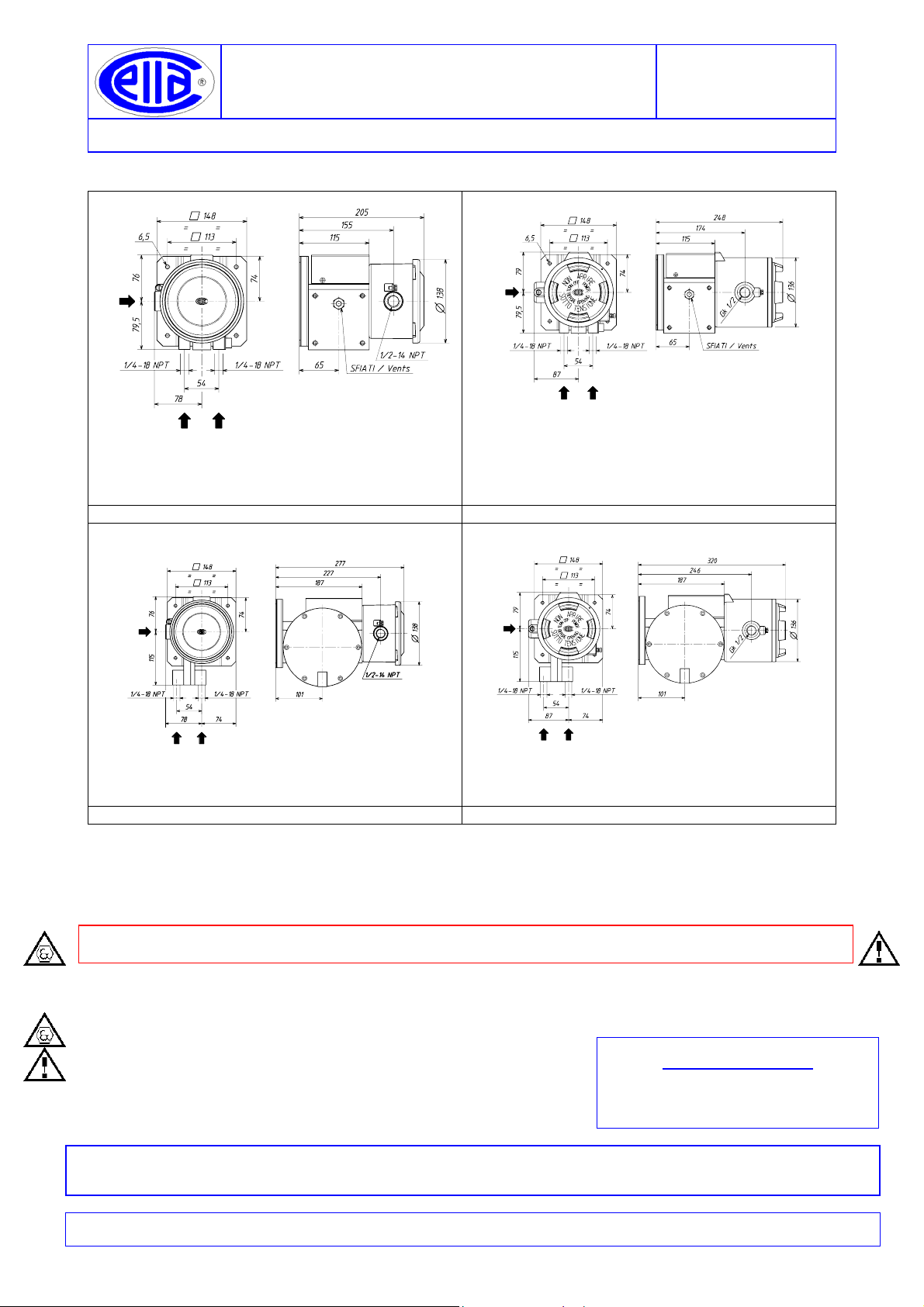
Models DW40, DW100, DW160
Models DA40, DA100, DA160
C
C
AB
AB
A Low pressure attachment
B High pressure attachment
Weight 6,2 kg dimensions in mm Weight 7,2 kg dimensions in mm
Models DW10
C
C Cable entry
A Low pressure attachment
B High pressure attachment
Models DA10
C
C Cable entry
AB
A Low pressure attachment
B High pressure attachment
Weight 8,2 kg dimensions in mm Weight 10 kg dimensions in mm
NOTE: dimensions and weights are not binding unless released on certified drawings.
CAUTION
• Before installing, using or carrying out maintenance on the instrument it is necessary to read and understand the
indications given in the attached Instruction Manual.
• The instrument must only be installed and maintained by qualified personnel.
• INSTALLATION IS TO BE CARRIED OUT ONLY AFTER CHECKING THAT INSTRUMENT CHARACTERISTICS
ARE CONSISTENT WITH PROCESS AND PLANT REQUIREMENTS
• The functional features of the instrument and its degree of protection are shown on the identification plate fixed to the
case.
SAFETY INSTRUCTIONS FOR USE IN HAZARDOUS ATMOSPHERES.
RECOMMENDATIONS FOR PRESSURE SWITCH SAFE USE.
All data, statements and recommendations supplied with this manual are based on information believed by us to be reliable. As
the conditions of effective use are beyond our control, our products are sold under the condition that the user himself evaluates
such conditions before following our recommendations for the purpose or use foreseen by him.
The present document is the property of ETTORE CELLA SPA and may not be reproduced in any form, nor used for any purpose
other than that for which it is supplied.
C Cable entry
A Low pressure attachment
B High pressure attachment
AB
C Cable entry
RELATED DOCUMENT
To authentified document with certificate
N° CESI 03 ATEX 004
Page 2
INSTRUCTION MANUAL
1. GENERAL NOTES
1.1 FOREWORD
The wrong choice of a series or a model, as well as the
incorrect installation, lead to malfunction and reduce
instrument life. Failure to follow the indications given in
this manual can cause damage to the instrument, the
environment and persons.
1.2 ALLOWED OVERRANGE
Pressures exceeding the working range can be
occasionally tolerated provided they remain within the
limits stated in the instrument features (vacuum or proof
pressure). Continuous pressures exceeding the working
range can be applied to the instrument, provided they
are clearly stated in the instrument features. The current
and voltage values stated in the technical specifications
and ratings must not be exceeded. Transitory
overranges can have a destructive effect on the switch.
1.3 MECHANICAL VIBRATIONS
Can generally lead to the wearing of some parts of the
instrument or cause false actuation. It is therefore
recommended that the instrument be installed in a place
where there are no vibrations. In cases where this is
impossible it is advisable to take measures to lessen the
effects (elastic supports, installation with the pin of the
microswitch positioned at right angles to the vibration
plane, etc.).
1.4 TEMPERATURE
Due to the temperature of both the environment and the
process fluid, the temperature of the instrument could
exceed the allowed limits (normally from -20° to +70°C).
Therefore, in case it does, suitable measures (protection
against heat radiation, fluid separators, cooling coils,
heated lockers) must be taken. The process fluid or its
impurities must not in any case solidify inside the
instrument chambers.
2. OPERATING PRINCIPLE
The differential pressure, acting on the sensitive
diaphragm element, determines its elastic deformation
which is used to actuate one or two electric
microswitches regulated at set point values. The
microswitches are of the snap acting type with automatic
reset. When the pressure moves away from the set
values, returning towards the normal values, the switch
is reset. The dead band (difference between the set
point value and the reset value) can be set or adjustable
(letter R in the contact codes).
NI-209E
Rev. 4 12/02
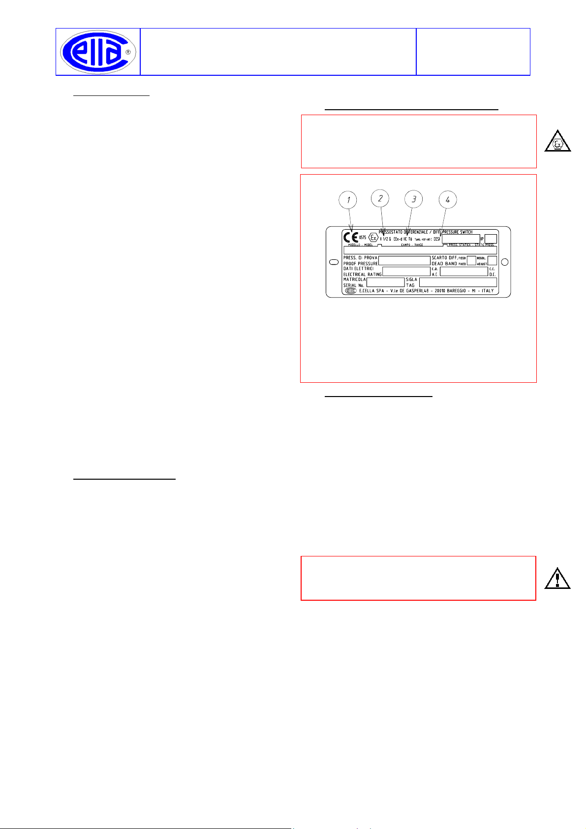
3. IDENTIFICATION PLATE AND MARKINGS
The instrument is fitted with a metal plate bearing all its
functional characteristics and – in case of explosionproof
execution (Series DA) – also the markings prescribed by
standard CEI EN 50014. Fig. 1 shows the plate mounted
on explosionproof instruments.
Fig. 1 - Explosionproof instruments plate
1 CE marking and identification number of the notified body
responsible for production surveillance.
2 Apparatus classification according to ATEX 94/9 CE
directive.
3 Type of protection and ambient temperature limits of
operation.
4 Notified body that issued the type certificate and number of
said certificate.
4. SET POINT REGULATION
Each microswitch is independent and can be regulated
by means of a screw (for adjustment) in such a way that
it is released when the pressure reaches (increasing or
decreasing) the desired value (set point).
The instrument is usually supplied with the switches set
at the setting range value nearest to zero (factory
calibration).
The instrument is supplied with an adhesive rating plate
showing the set point calibration value. With factory
calibration the values are not indicated on the ratings as
these are temporary and will be modified with the
definitive values.
Prior to installation the instrument must be calibrated
and the definitive calibration values written on the
adhesive rating plate using a suitable indelible ink pen.
If the instrument has been ordered with a specific
calibration, it is a good rule to check the calibration
values marked on the relevant adhesive label, prior to
installation.
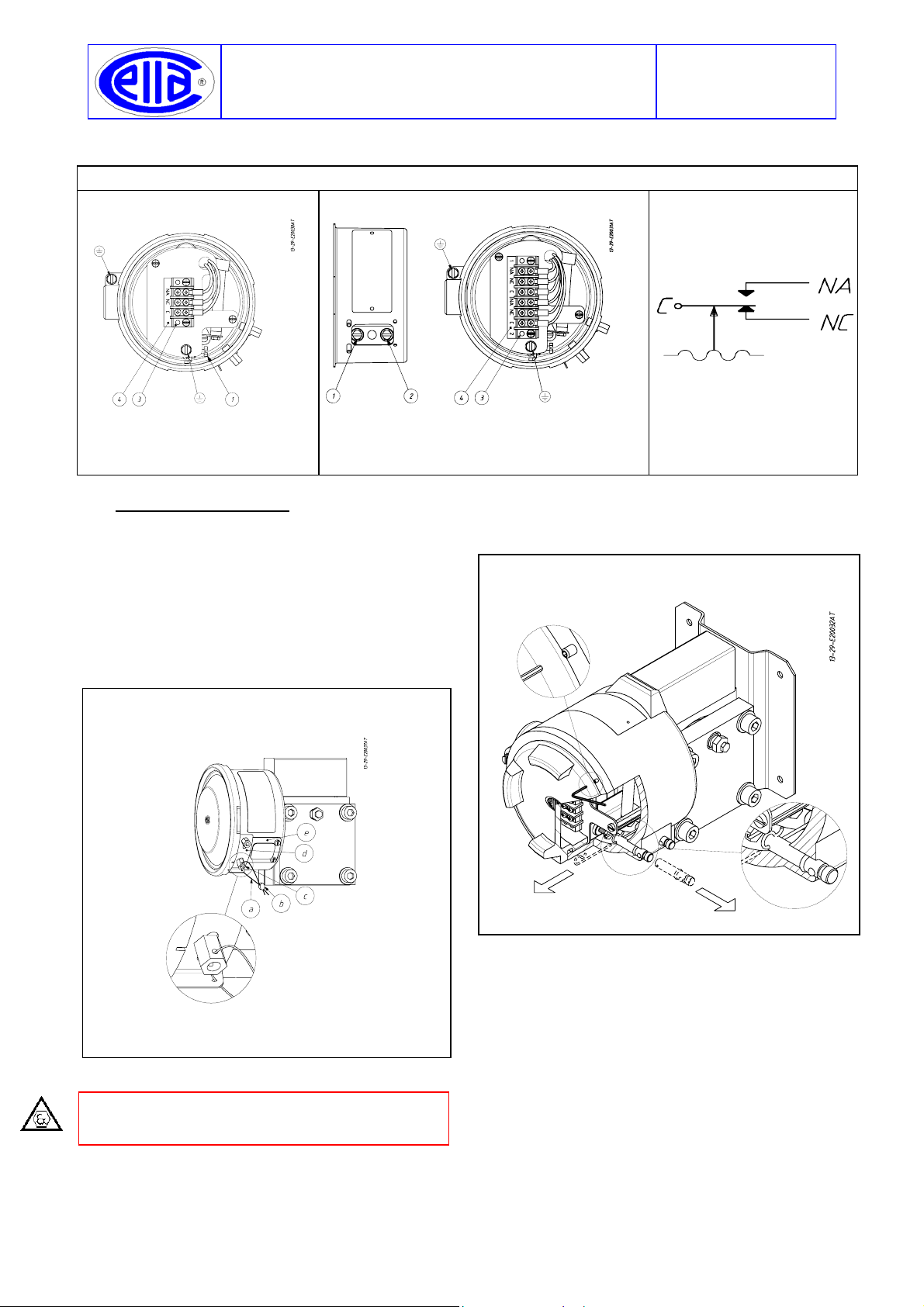
The position of the adjustment screws is given in fig. 2.
The effect that the direction of rotation of the adjustment
screws has is described on the adhesive plate.
Page 3
INSTRUCTION MANUAL
Fig. 2 - Electrical connections and adjustment screws
One contact instruments Two contact instruments
NI-209E
Rev. 4 12/02
Microswitch electrical circuit:
State of the contacts at atmospheric
pressure
1 - Microswitch set point calibration screw
3 - Terminal block
4 - Electrical connection identification
plate
5. SET POINT CALIBRATION
In order to proceed with the calibration and the periodical
functional verification of the instrument a suitable
calibration circuit (fig. 5) and an adequate pressure
source is required.
5.1 PRELIMINARY OPERATIONS
Weatherproof pressure switches (Series DW) (Fig.
3)
Remove the blocking device fixed to the side of the
instrument case and the adjustment screw access plate.
Remove the cover be rotating it anticlockwise.
Fig. 3 -
and plumbing
Weatherproof pressure switch cover blocking device
1 – Microswitch 2 set point calibration screw
2 – Microswitch 1 set point calibration screw
3 – Terminal block
4 – Electrical connection identification plate
Designation of the contacts:
C - common
NA - Normally open
NC - Normally closed
Loosen the locking headless screw situated on the cover
using a 1,5 hexagonal key then unscrew the cover.
Remove the internal blocking device inserted on the
closure plugs and slide out the plugs.
Fig. 4 -
Explosionproof pressure switch cover blocking device
a) Plumbing wire
b) Plumbing
c) Blocking nut
Explosionproof pressure switches (Series DA) (Fig.
4)
CAUTION: do not open the cover of explosionproof
pressure switches (Series DA) when energized, in
explosive atmospheres.
c) Blocking bracket
e) Adjustment screw access
plate
5.2 CALIBRATION CIRCUIT AND OPERATIONS
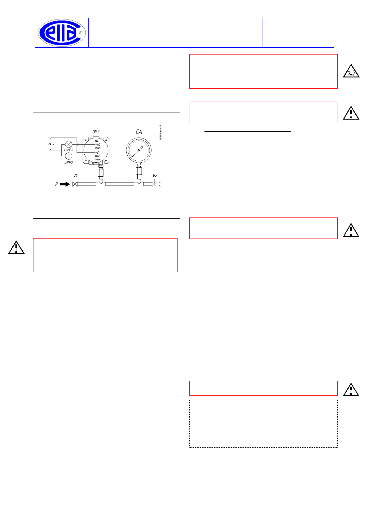
Prepare the control circuit as indicated in Fig.5.
The warning lamps should be connected to contact 1 or
2 in the NO or NC position according to the required
contact action.
Connection of C and NO terminals
• If the circuit is open at the working pressure, the switch
closes the circuit as the pressure increases when the
desired value is reached.
• If the circuit is closed at the working pressure, the
switch opens the circuit as the pressure decreases
when the desired value is reached.
Connection of C and NC terminals
• If the circuit is closed at the working pressure, the
switch opens the circuit as the pressure increases
when the desired value is reached.
• If the circuit is open at the working pressure, the switch
closes the circuit as the pressure decreases when the
desired value is reached.
Page 4
INSTRUCTION MANUAL
The test instrument should have a measurement range
approximately equal to or slightly wider than the pressure
switch range and should have an accuracy consistent
with the precision required to calibrate the set point.
The pressure switch must be mounted in the normal
installation position, i.e. with the pressure connection
downwards; the instrument must be connected to the
pressure source by the + pipe inlet while the - pipe inlet
must be at atmospheric pressure.
Fig. 5 -
DPS – Differential pressure switch
CA – Test pressure gauge
V1 - Inlet valve
V2 – Discharge valve
P - Pressure source
Avoid forcing the elastic support of the microswitch by
hand or with tools. This could affect the instrument
functioning.
CAUTION: if the switch is of the kind with adjustable
dead band (letter R of contacts code) before proceeding
with the following operations it is necessary to proceed
with the adjustment of the dead band (see attachment
NI-704E).
Increase the pressure in the circuit up to the desired set
point value for the first microswitch.
Use a wide bladed screwdriver, as indicated on the
adhesive plate, until the relative lamp turns on (or turns
off).
- If the instrument is equipped with only one contact the
calibration is complete.
- If it is equipped with two contacts continue in the
following manner.
Vary the pressure until the desired set point value for the
second microswitch is reached (fig. 2).
Act on the adjustment screw of the second contact.
Repeat former operations on the first contact, then
operations on the second contact, until the required set
point precision is obtained. This is necessary due to the
reciprocal influence which the microswitches have with
the sensitive element of the instrument.
Check the calibration values (varying the pressure in the
circuit accordingly) and record them on the adhesive
plate using a pen with indelible ink.
5.3 FINAL OPERATIONS
Disconnect the instrument from the calibration circuit.
Weatherproof pressure switches (Series DW)
Take the cover, ensure that the sealing gasket is
correctly fitted into its seat, insert the cover onto the
case, with the blocking gap positioned in
correspondence to the blocking bracket.
Turn the cover clockwise closing it tightly. Mount the
adjustment screw access plate, then the blocking device
as in Fig.3.
Explosionproof pressure switches (Series DA).
Calibration circuit
Test fluid:
air for P ≤ 10 bar
water for P > 10 bar
NI-209E
Rev. 4 12/02
Insert the closure plugs of the adjustment screw access
holes, block them using the internal device and if
necessary seal them with plumbing. Screw on the cover
and block it using the headless screw with which it is
equipped (Fig. 4).
Replace the supplied protection caps on the pressure
attachment and cable conduit.
IMPORTANT: the protection caps should only be
definitively removed during the connection steps (see
§6).
6. MOUNTING AND CONNECTIONS
6.1 MOUNTING
Surface mount the instrument by means of the holes
provided, or pipe mount using the appropriate bracket
(see Fig. 9).
The chosen position must be such that vibrations, the
possibility of shocks or temperature changes are within
tolerable limits. With gas or vapour process fluid, the
instrument must be positioned higher than the pipe inlet
(see Fig. 8). With a liquid process fluid, the instrument
can be positioned higher or lower, indifferently (see Fig.7
and 8).
6.2 PRESSURE CONNECTIONS
Connecting lines are an integral part of the instrument in
transmitting the measured variable from the measuring
point to the instrument.
For a correct installation it is necessary to:
Mount a shut-off valve with drain (root valve) on each
process pipe inlet to allow the instrument to be excluded
and the connection tubing to be drained. It is
recommended that said valve has a capstan blocking
device aimed at preventing it being activated casually
and without authorisation.
Mount a 3 valve manifold near the instrument to permit
possible functional verification on site and removal of the
instrument. It is recommended that the manifold is made
up of two service valves, one by-pass valve and two
suitably connected drain plugs. The three valves with the
drains can be reunited by a single device called a “Three
valve manifold”.
Mount a three piece joint onto the threaded attachment
of the instrument to permit the easy mounting or removal
of the instrument itself.
Carry out the connection using a flexible tube in such a
way that variations in the temperature of the tube itself
do not force the instrument attachment.
Ensure that all the pressure connections are airtight. It is
important that there are no leakage in the circuit.
Close root valves, the two service valves, drain plugs
and open the by-pass valve.
NOTE: if the instrument is used for level control in
tanks under pressure it is recommended that installation
is carried out according to the diagram in figure 8;
ensuring that:
• the distance K is greater than 0.5 m;
• the seal pot B has a sufficient capacity to maintain
the liquid level at the maximum height over time.
Page 5
INSTRUCTION MANUAL
6.3 ELECTRICAL CONNECTIONS
It is recommended to carry out the electrical connections
according to the applicable standards. In case of
explosionproof instruments (Series DA) see also the
Standard EN-60079-14. If the electrical connection is
carried out in a protected tube, it shall be made so that
condensate is prevented from entering instrument
enclosure.
The arrangement shown in figure 7 and 8 is therefore
recommended.
CAUTION: fittings used for the electrical connection of
the pressure switch Series DA (explosionproof) shall be
certified to Standards EN 50014 and 50018, and shall
guarantee instrument degree of protection (IP65).
Check that there is no power in the lines. Remove the
cover and carry out the cabling and connections to the
terminal block (see Fig. 2). Flexible cables with a
maximum section of 1.2 mm
recommended using pre-insulated fork thimbles. Do not
touch the adjustment screws and do not bend the
elastic microswitch supports in order to prevent the
instrument calibration being altered. Ensure that no
deposits or wire ends remain inside the case.
As soon as connection steps are completed, mount the
cover on and make sure it is tight and blocked See Fig. 3
and 4.
6.4 SPECIAL NOTE FOR INSTALLATION OF
CATEGORY 1/2 G PRESSURE SWITCHES
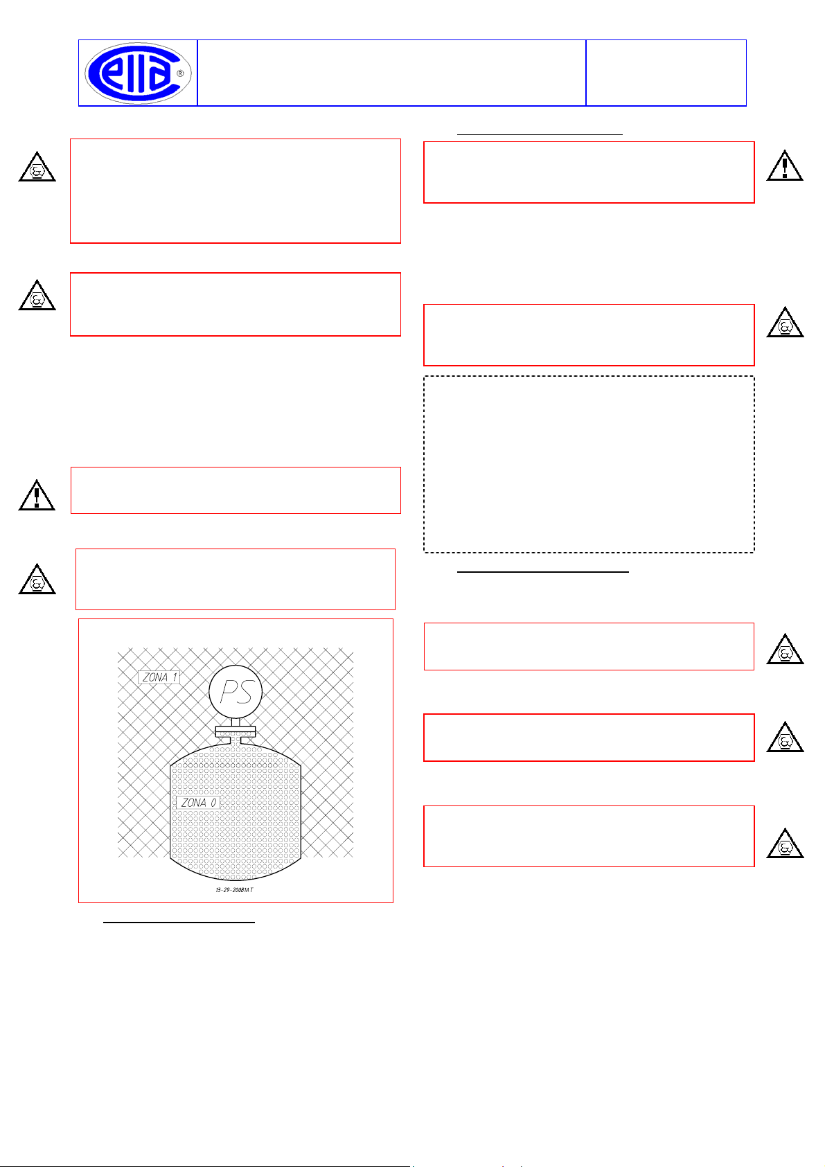
Explosionproof pressure switches (Series DA) can be
installed on processes requiring apparatus of group II
category 1 in an ambient requiring apparatus of group II
category 2 (see Fig. 6).
Fig. 6 - Installation of Group II Cat. 1 / 2 G instruments
2
(16AWG) are
NI-209E
Rev. 4 12/02
8. PUTTING INTO OPERATION
As the signal transmitted by the instrument is used in a
complex system, it is necessary that the means of
putting it into operation are established by personnel in
charge of the plant.
The instrument comes into operation as soon as the root
valves are opened and then, afterwards, the service
valve attached to the instrument + inlet pipe is opened,
the by-pass valve closed and the service valve attached
to the instrument - inlet pipe is opened. Any possible
drainage of the connection tubing can be carried out by
opening the drains positioned on the instrument.
In case of explosionproof instruments (Series DA), initial
inspections are to be carried out according to customer
procedures and at least in accordance with Standard
EN-60079-17.
NOTE: if the instrument is used for level control in
tanks under pressure and is installed according to the
diagram in Fig. 10 proceed as follows:
Close the root valves V1 and V2 open the valves V3 V4
V5 (the service and by-pass valves). Fill with the process
fluid, from plug SB positioned on the seal pot B, bleeding
air from the plug S positioned on the seal pot near the
V2 valve. Then close S and top up the liquid in B.
Remove air from the breather plug S+ and S- positioned
on the instrument, topping up the liquid in B. Close the
plug SB and the by-pass valve V5 and open the root
valves V1 and V2. The instrument is ready for use.
9. FUNCTIONAL VERIFICATION
This will be carried out according to the Client’s control
procedures. Series DW instruments can be verified on
the plant if installed as illustrated in Fig. 7 or 8.
The instruments Series DA may be checked on site only
if apparatus suitable for explosive atmospheres are used
and provided that the electric line is not energized.
If this is not the case it is necessary to stop operation,
dismount by means of the three piece joints and carry
out the verification in a test room.
CAUTION: do not open the cover of explosionproof
pressure switches (Series DA) when energized, in
explosive atmospheres.
Verification consists in checking the calibration value
and possibly regulating the adjustment screw (see
par.5).
In case of explosionproof instruments (Series DA),
inspections of the electrical installation are to be carried
out also according to customer procedures and at least
in accordance with Standard EN-60079-17.
7. INSTRUMENT PLUMBING
Weatherproof pressure switches (Series DW)
The plumbing, aimed as a guarantee against possible
tampering of the calibration and electrical connections,
can be carried out using a flexible steel wire (a) inserted
into the holes in the locking nut (c) and the bracket (d)
provided for this purpose (see Fig. 3).
Explosionproof pressure switches (Series DA)
Plumbing is not necessary as the cover is blocked with a
headless screw, the closure plugs of the adjustment
screw access holes are blocked by means of the internal
blocking device and the instrument does not have to be
opened when installed (see Fig. 4).
Page 6
NI-209E
INSTRUCTION MANUAL
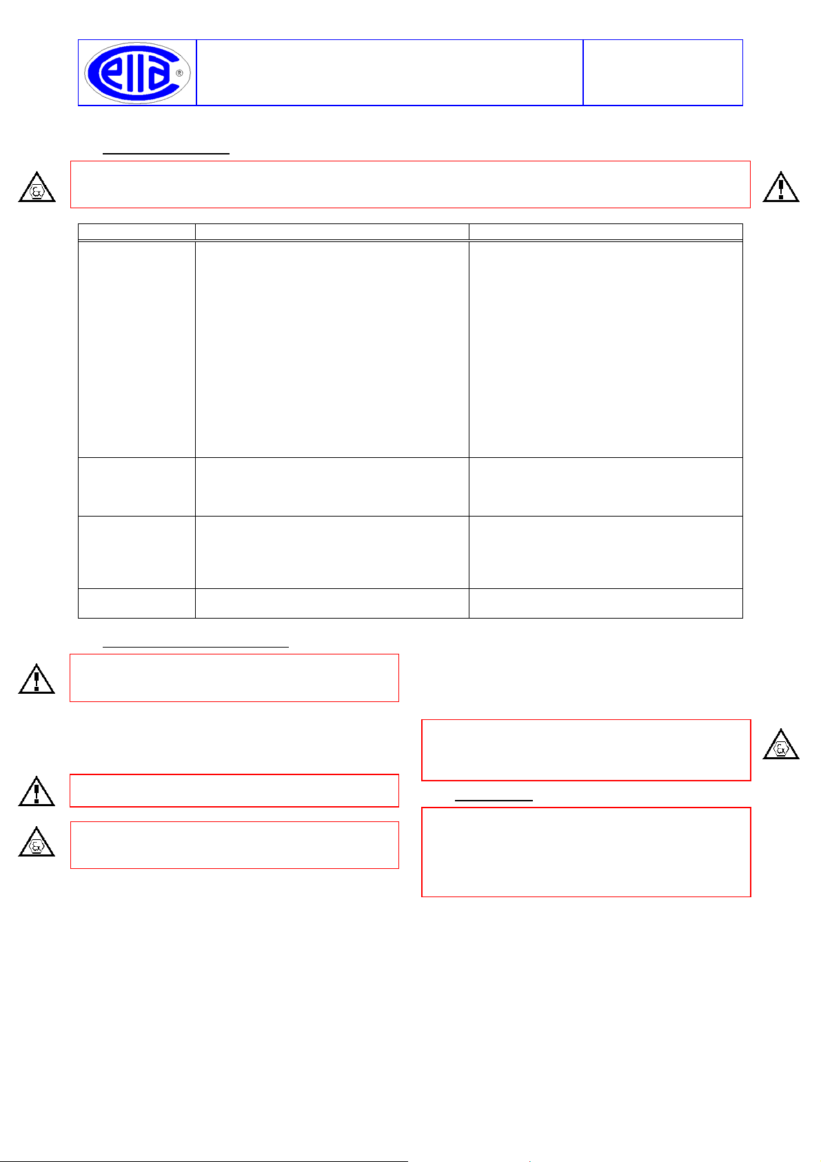
10. TROUBLESHOOTING
IMPORTANT NOTE: operations involving replacement of essential components must be carried out at our
workshop, especially for instruments with explosionproof certificate; this is to guarantee the user the total and
correct restoration of the product original characteristics.
MALFUNCTION PROBABLE CAUSE REMEDY
Set point shift
Slow response
No actuation or
undue actuation
Undue actuation
11. STOPPING AND DISMOUNTING
Before proceeding with these operations ensure that the
plant or machines have been put into the conditions
foreseen to allow these operations.
With reference to figures 7 and 8
Remove the power supply (signal) from the electrical
line.
Close the service valve (2) and open the by-pass valve.
Carefully open the drains.
Do not dispose of the process fluid into the environment,
if this can cause pollution or damage to people.
Unscrew the three piece joint (1).
CAUTION: do not open the cover of explosionproof
pressure switches (Series DA) when energized, in
explosive atmospheres.
Unscrew the three piece joint (11) (electrical cable
tubing).
Remove the instrument cover and disconnect the
electrical cables from the terminal block and earth
screws.
Air bubbles in the connection lines
(condensation in the case of use of gas;
excluding models DW10 and DA10)
Solid particles deposited inside the
measurement chambers of the instrument
(excluding models DW10 and DA10)
Permanent deformation of the sensitive
element due to fatigue or non-tolerated overranges
Variation of the elastic features of the
sensitive element due to its chemical
corrosion.
Leakage of filling fluid (excluding models
DW10 and DA10).
Clogged or obstructed connection line.
Root or service valve partially closed.
Too viscous fluid.
Root or service valve closed.
By-pass valve open.
Microswitch contacts damaged.
Loosened electrical joints.
Interrupted or short-circuited electrical line.
Accidental shocks or excessive mechanical
vibrations.
Remove the screws fixing the case to the panel (or pipe)
and remove the instrument, taking care to slide the
electrical conductors out from the case.
Replace the instrument cover. Insulate and protect the
conductors remaining on the plant. Temporarily plug the
pipes disconnected from the instrument.
In case of explosionproof instruments (Series DA) it is
recommended to follow - at least – the standard EN60079-17 for the withdrawal from service of electrical
apparatus.
12. DEMOLITION
The instruments are mainly made of stainless steel and
aluminium and therefore, once the electrical parts have
been dismounted and the parts coming into contact with
fluids which could be harmful to people or the
environment have been properly dealt with, they can be
scrapped.
Drain using the appropriate plugs
Dismount the measurement chambers and
clean them (during the mounting phase the
screw locking couple is 80 N/m)
Recalibrate or replace the sensitive element.
Recalibrate or replace the sensitive element
with another made of a suitable material. If
necessary apply a fluid separator
Send to the constructor for checking
Check and clean line.
Open valve.
Provide instrument with suitable fluid
separator.
Open the valve.
Close the valve.
Replace the microswitch.
Check all electrical joints.
Check the conditions of the electrical line.
Modify the mounting.
Rev. 4 12/02
Page 7
INSTRUCTION MANUAL
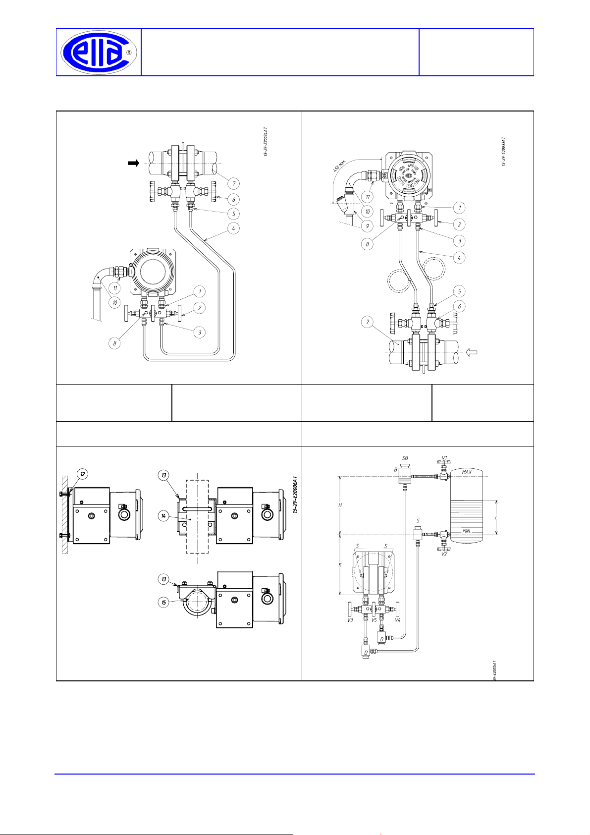
Fig. 7 - Example of connections - Fig. 8 - Example of connections -
WEATHEPROOF EXPLOSIONPROOF
-+
NI-209E
Rev. 4 12/02
1 - Three pieces fitting
2 - Three valves manifold
3 - Three pieces fitting
4 - Piping
5 - Three pieces fitting
6 - Root valve with drain
7 - Filter or nozzle
8 - Check inlet and drain plug
9 - Blocking joint
10 - Curve
11 - Three pieces fitting
12 - M6 screws (N°4)
13 - Bracket for 2” pipe
14 - Vertical pipe
15 - Horizontal pipe
Fig. 9 - Example of mounting Fig. 10 - Level check of tanks under pressure using wetted
tube
Surface mounting
Montaggio a parete
2” pipe mounting
Montaggio su staffa
per tubo da 2”
+
-
+-
NOTE With gas or vapour process fluid, the instrument must be positioned higher than the pipe inlet (see Fig. 8). With
a liquid process fluid, the instrument can be positioned higher or lower, indifferently (see Fig. 7 e 8).
ETTORE CELLA SPA Viale de Gasperi, 48 - Casella Postale (P.O. Box) 96 - I 20010 Bareggio (MILANO) ITALY
Telefoni +39 029036.1146/1237/1241 - FAX +39 029036.1331 e-mail: [email protected]
 Loading...