

Page 1
celexon.
TM
Installaon Guide
celexon ceiling recessed electric
Professional Plus screen
Thank you for purchasing this celexon product. Before installing
the projector screen, please read the following instrucons carefully
and keep for future reference.
Page 2
DE:
Auf http://www.celexon.de finden Sie durch Eingabe der Identifikationsnummer „CX1005“
im Suchfeld die aktuelle Version dieser Bedienungsanleitung in Ihrer jeweiligen
Landessprache zum Download.
Die Konformitätserklärung und die zu diesem Produkt gültigen Zertifizierungen sind auf
unserer Webseite http://de.celexon.com einsehbar.
EN:
At www.celexon.co.uk you can find the latest version of the manual and download it simply
by searching the identification number “CX1005” in the search field.
The declaration of conformity and the relevant certificates for this product are available on
our website http://de.celexon.com.
FR:
En vous rendant sur http://www.celexon.fr et en entrant le numéro d‘identification
„CX1005“ dans la barre de recherche, vous pourrez télécharger la version française la plus
actuelle de cette notice d‘utilisation.
La déclaration de conformité ainsi que les certificats en cours de validité de ce produit
sont disponibles sur notre site internet http://fr.celexon.com.
NL:
Op http://www.celexon.nl vind u door ingave van het identificatienummer „CX1005“ in
het zoekveld de actuele versie van deze gebruikershandleiding in uw taal als download.
De conformiteitsverklaring en de voor dit product geldige certificaten kunnen op onze
website http://nl.celexon.com worden ingezien.
SE:
På http://uk.celexon.com hittar du den aktuella versionen av din bruksanvisning på ditt
spårk för nedladdning genom att skriva in identifikationsnumret „CX1005“ i sökrutan.
Försäkran om överensstämmelse och de gilitiga certifikaten för denna produkt kan hittas
på hemsidan http://uk.celexon.com.
PL:
Na stronie http://www.celexon.pl znajdą Państwo aktualną wersję instrukcji obsługi.
W polu szukaj należy podać następujący numer: „CX1005“.
Deklaracja zgodności oraz certyfikaty dotyczące produktu są dostępne na stronie
http://de.celexon.com.
ES:
Puede descargar la versión actual de este manual de uso, en el idioma correspondiente
en http://www.celexon.de introduciendo el código de identificación “CX1005” en la barra
de búsqueda.
Puede encontrar la declaración de conformidad y los certificados correspondientes para
este producto en nuestra página web http://es.celexon.com.
1
Page 3
Safety instructions
• Do not start installation before reading the complete installation manual
and the safety warnings.
• This product should only be installed by qualified personnel (with mechanical
and electrical experience).
• If necessary, carry out the installation with another person to ensure safe
installation.
• Tighten the screws but ensure that they are not overtightened as this may
cause damage.
• This product is designed for indoor use only. Outdoor use could result in
damage to the product and may cause injury.
• Hanging loads must be tested at least twice a year for strength and carrying
capacity.
Disclaimer
The information in this document is subject to change without prior notice.
Changes will be documented in future editions of this manual. The manufacturer
does not guarantee accuracy of the information contained in this document.
Important
Please read the following instructions carefully and keep them for future reference.
The manufacturer does not accept liability for any damage to property or personal
injury if the screen is used outside of the recommended specifications, or if it is
installed improperly.
Do not use the screen near extreme temperatures (radiators or air conditioning
units). Do not install the screen in direct sunlight or in front of a window. Due to the
temperature-sensitive PVC surface, damage may occur to the projection fabric.
We recommend to wait approx. 2 hours after delivery of the screen before you start
installation so that the fabric can acclimatise, particularly when the fabric came in
from a cold environment to a warm one.
Please avoid any stains on the fabric as it may not be possible to remove them.
2
Page 4
Cleaning instructions
Never clean the screen with alcohol or other cleaning agents containing solvents.
Use only a soft and clean cloth with a mild soapy solution. Avoid contact with pointed or sharp objects. These could damage the fabric.
In the box
Prior to installation, please check that you have all the piece parts listed below.
If any piece parts are missing, please contact the dealer where you purchased the
product and wait with the installation until you have received the missing part.
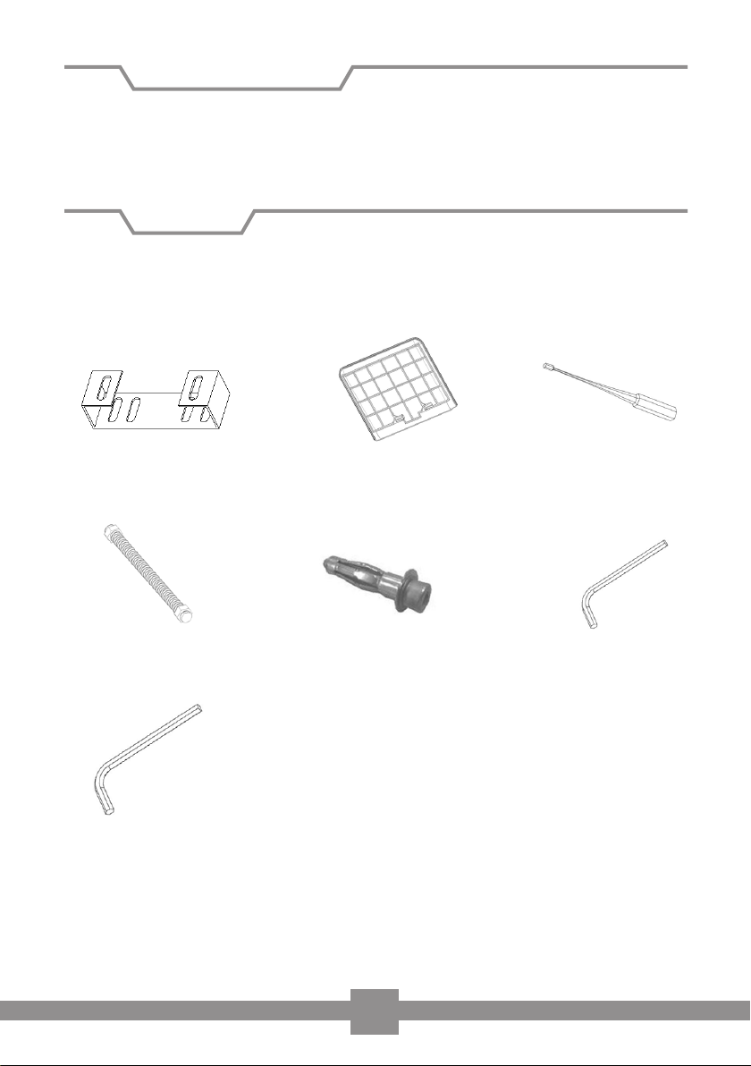
2 x Mounting brackets (A) 2 x Inspection covers (B)
4 x Threaded rod (D)
1 x Allen key (8mm) (L)
4 x Wall plugs (E) 1 x Allen key (5mm) (F)
1 x Allen Key Tool
(for end stop
positions) (C)
3
Page 5
Installation of screen
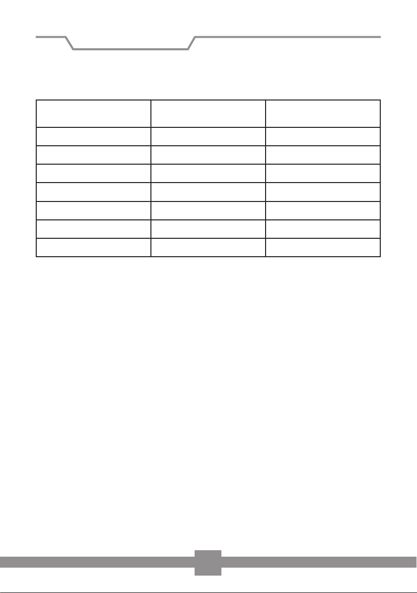
1. Take the cut-out dimensions from the list below and cut an appropriate hole
into your suspended ceiling.
Width
Viewing area
160 cm 202 cm 11 cm
180 cm 222 cm 11 cm
200 cm 244 cm 11 cm
220 cm 264 cm 11 cm
240 cm 284 cm 11 cm
280 cm 329 cm 13,5 cm
300 cm 349 cm 13,5 cm
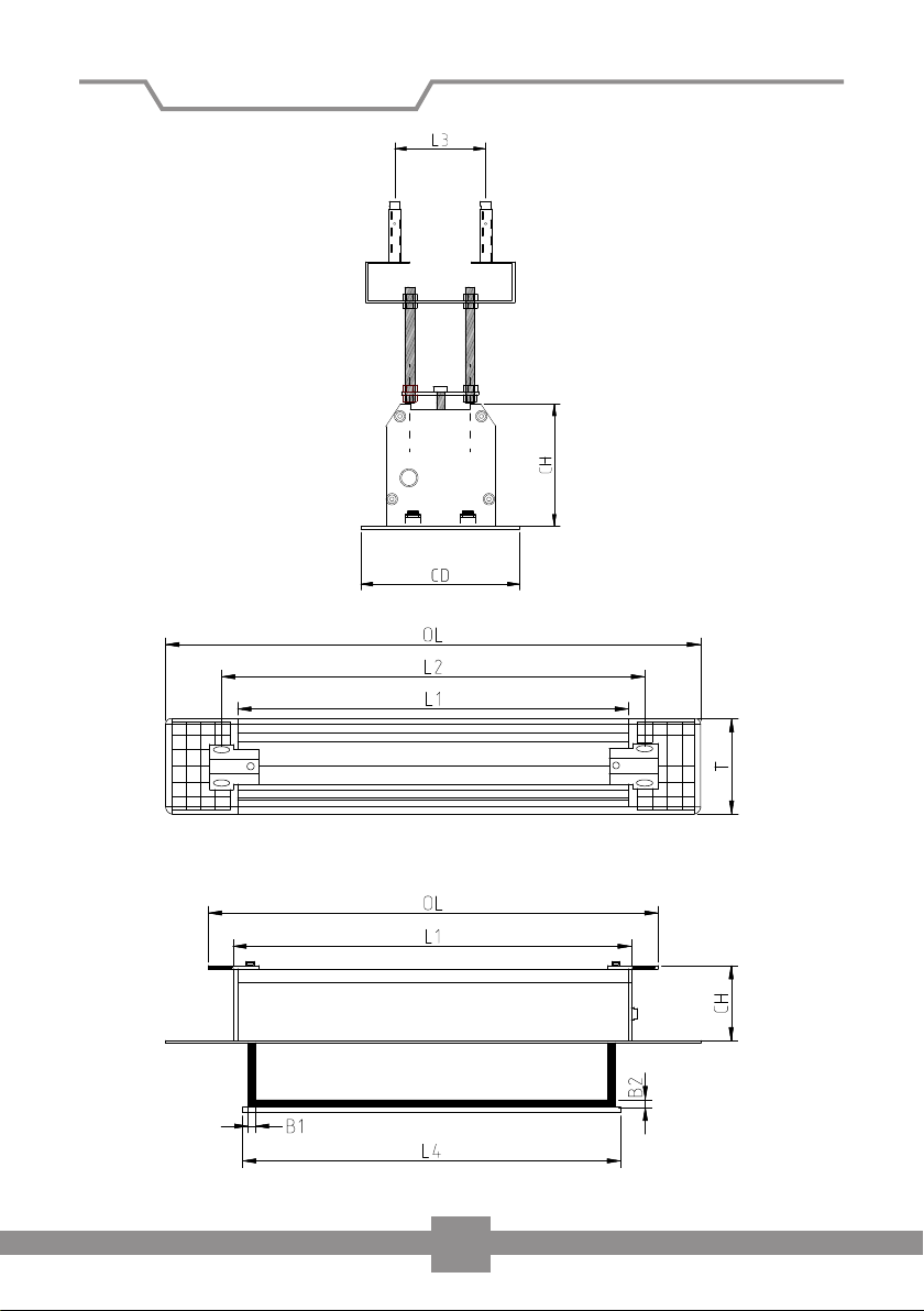
Alternatively, you can determine the cut-out dimensions as follows:
Measure the length „L“ as well as the depth „CD“ of the screen housing as shown in
the two figures below. Add 190mm to length “L” and deduct 25mm from the width
„CD“.
Length
Ceiling cut-out
Width
Ceiling cut-out
4
Page 6
Installation of screen
Figure 1
5
Page 7
Installation of screen
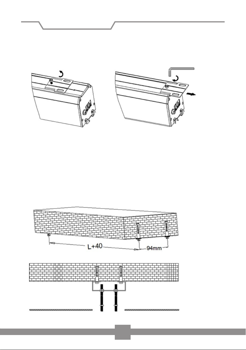
2. Loosen the screws of the mounting plate above the screen housing. Slide the
mounting plates to the ends of the housing and tighten the screws again (Figure 2). Please ensure that the holes for the threaded rods are not covered by the
housing.
Figure 2
3. Drill 4 holes in the load bearing ceiling and insert the wall plugs E. The distance
between the holes should be L + 40mm x 94mm. If necessary, use other wall
plugs and screws suitable for your specific requirements.
Now attach the two mounting brackets (A) to your ceiling. Please ensure that
brackets are securely fastened and provide a safe installation. Then attach the 4
threaded rods (D) to the mounting brackets and attach a nut to each rod (Fig 3).
Figure 3
6
Page 8
Installation of screen
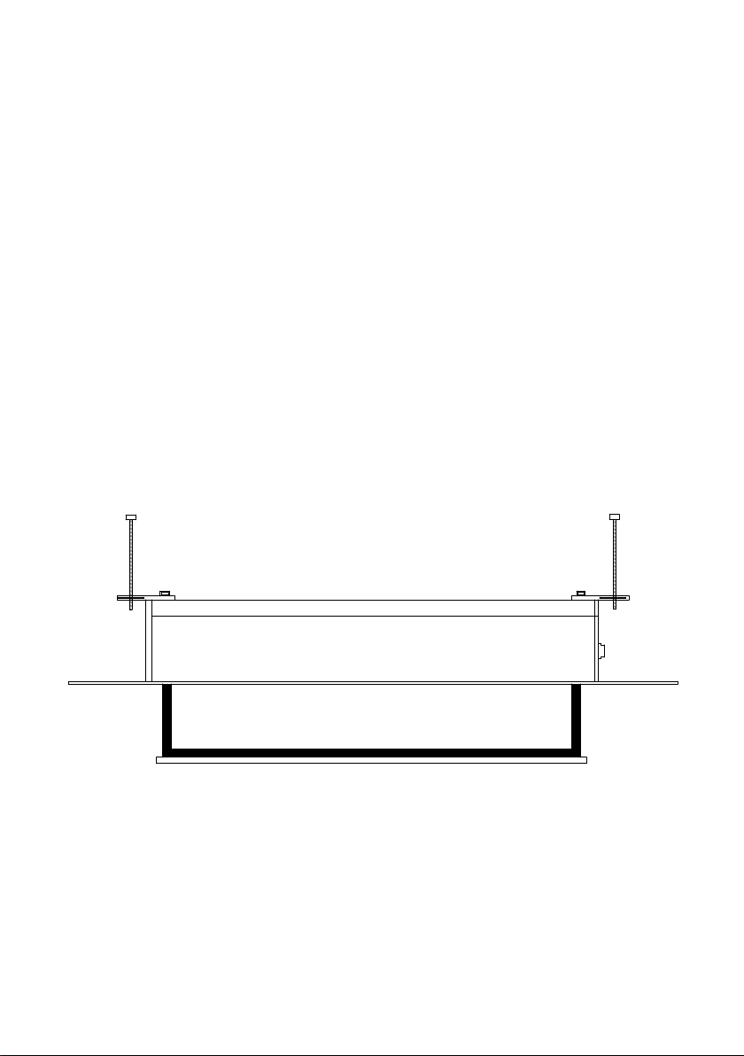
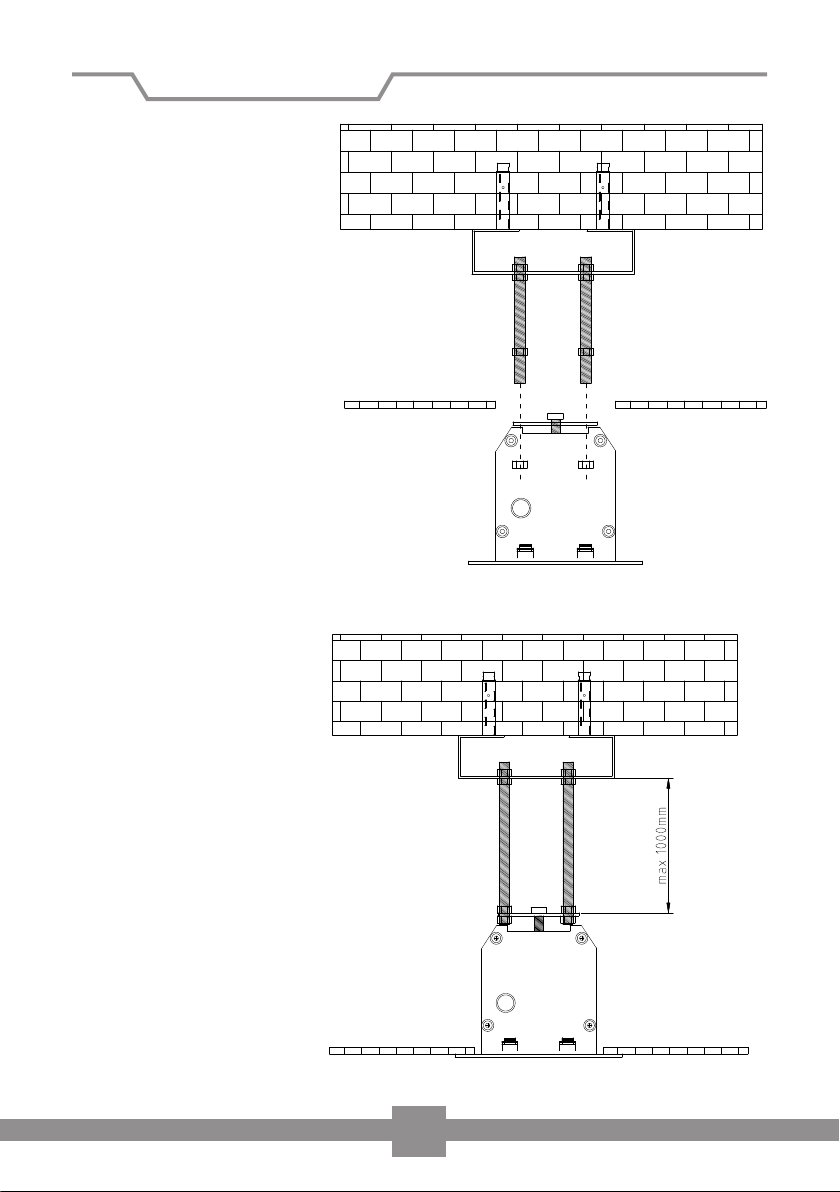
4. Insert the housing into
the ceiling cut-out.
Please ensure that the
four threaded rods
are inserted into the
holes of the mounting
brackets. Tighten the
nuts on each threaded
rod to secure the screen
(see fig 4).
5. Move the screen into a
horizontal position
tightening the nuts and
eliminating any gap
between the ceiling and
the trim (Fig 5). Use a
spirit level to ensure that
the screen is perfectly
horizontal.
Suspended
ceiling
Figure 4
Threaded rods
pass through
the holes
Suspended
ceiling
Figure 5
Nuts
7
Page 9
Installation of screen
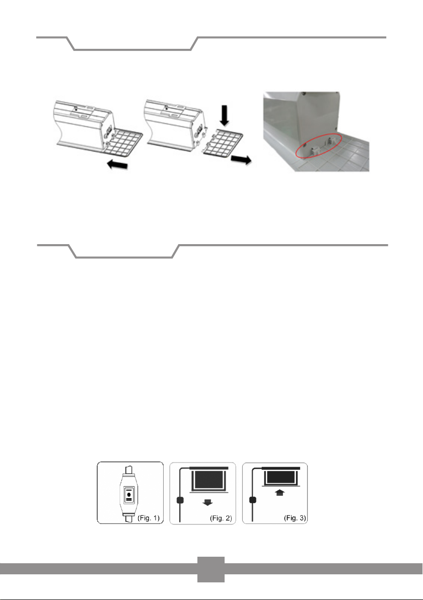
6. Finally attach the inspection covers (B) to the sides of the housing. To dismantle
the screen, pull the covers down and away from the housing (Fig 6).
Figure 6
This completes the installation.
Screen operation
Operating the screen via wall switch
Plug the power cable into the socket (ensure correct voltage). Position the cable so
that it does not present a hazard or comes into contact with hot surfaces. You may
require an extension lead.
To lower the screen (see fig 2)
When you set the switch to < + >, the screen will come down and stop automatically at the lower stop position.
To retract the screen (see fig 3)
When you position the switch to < - >, the screen will automatically retract into its
housing and stop at the upper stop position.
To stop the screen
If you position the switch to < 0 > , the screen will stop at that position.
8
Page 10
Installation of screen
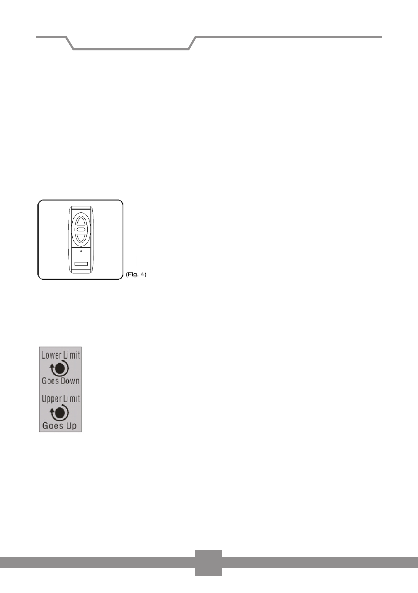
Wireless operation (g 4) (Optional)
To lower the screen:
If you press the lower button on the remote control, the screen will automatically
lower itself and stop at the lower stop position (when fully extended).
To retract the screen:
If you press the top button on the remote control, the screen will automatically
retract into its housing and stop when fully retracted.
To stop the screen:
If you wish to stop the screen, then press the middle button on your remote control.
To adjust the stop positions
Please note that any damage caused by incorrect tempering of the stop positions
will not be covered under the warranty.
Lower Limit — Adjusting the lower stop limit is only possible when
the screen is fully extended. To extend the lower limit, turn the ‘lower
limit’ Allen key hole clockwise.
Upper Limit — Adjusting the upper stop limit is only possible when
the screen is fully retracted into the housing. To adjust the upper limit,
turn the ‘upper limit’ Allen key hole clockwise.
9
Page 11
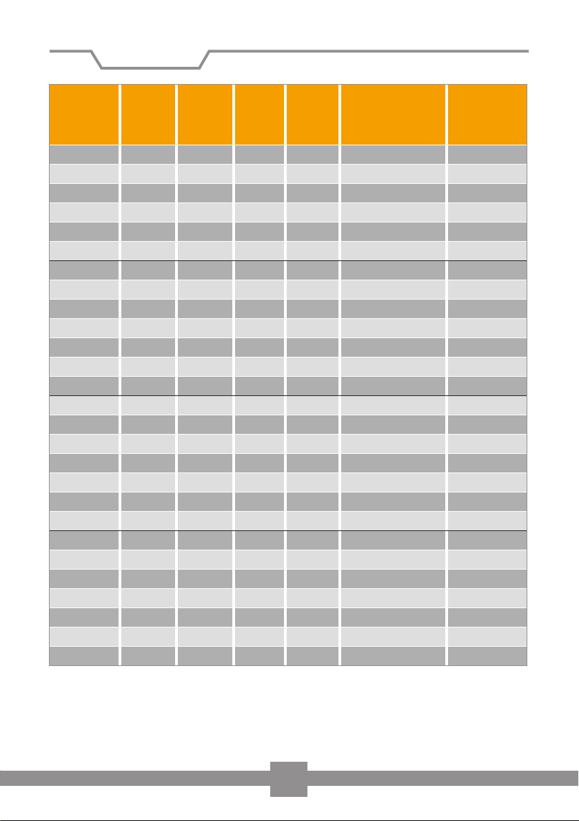
Dimensions
Product
descriptions
(W x H)
160x160 cm 182,6 cm 186,6 cm 9,4 cm 172,2 cm 206,6x10,3x13,6 cm 201,6x11,1 cm
180x180 cm 202,6 cm 206,6 cm 9,4 cm 192,2 cm 226,6x10,3x13,6 cm 221,6x11,1 cm
200x200 cm 224,6 cm 228,6 cm 9,4 cm 214,2 cm 248,6x10,3x13,6 cm 243,6x11,1 cm
220x220 cm 244,6 cm 248,6 cm 9,4 cm 234,2 cm 268,6 x10,3x13,6 cm 263,6x11,1cm
240x240 cm 264,6 cm 268,6 cm 9,4 cm 254,2 cm 288,6x10,3x13,6 cm 283,6x11,1 cm
280x280 cm 309,8 cm 313,8 cm 9,4 cm 296,3 cm 312,4x12,7x16,0 cm 328,8x13,5 cm
160x120 cm 182,6 cm 186,6 cm 9,4 cm 172,2 cm 206,6x10,3x13,6 cm 201,6x11,1 cm
180x135 cm 202,6 cm 206,6 cm 9,4 cm 192,2 cm 226,6x10,3x13,6 cm 221,6x11,1 cm
200x150 cm 224,6 cm 228,6 cm 9,4 cm 214,2 cm 248,6x10,3x13,6 cm 234,6x11,1 cm
220x165 cm 244,6 cm 248,6 cm 9,4 cm 234,2 cm 268,6x10,3x13,6 cm 263,6x11,1 cm
240x280 cm 264,6 cm 268,6 cm 9,4 cm 254,2 cm 288,6x10,3x13,6 cm 283,6x11,1 cm
280x210 cm 309,8 cm 313,8 cm 9,4 cm 296,3 cm 312,4x12,7x16,0 cm 328,8x13,5 cm
300x225 cm 329,8 cm 333,8 cm 9,4 cm 316,3 cm 339,5x12,7x16,0 cm 348,8x13,5 cm
160x90 cm 182,6 cm 186,6 cm 9,4 cm 172,2 cm 206,6x10,3x13,6 cm 201,6x11,1 cm
180x102 cm 202,6 cm 206,6 cm 9,4 cm 192,2 cm 226,6x10,3x13,6 cm 221,6x11,1 cm
200x113 cm 224,6 cm 228,6 cm 9,4 cm 214,2 cm 248,6x10,3x13,6 cm 243,6x11,1 cm
220x124 cm 244,6 cm 248,6 cm 9,4 cm 234,2 cm 268,6x10,3x13,6 cm 263,6x11,1 cm
240x135 cm 264,6 cm 268,6 cm 9,4 cm 254,2 cm 288,6x10,3x13,6 cm 283,6x11,1 cm
280x158 cm 309,8 cm 313,8 cm 9,4 cm 296,3 cm 312,4x12,7x16,0 cm 328,8x13,5 cm
300x169 cm 329,8 cm 333,8 cm 9,4 cm 316,3 cm 339,5x12,7x16,0 cm 348,8x13,5 cm
160x110 cm 182,6 cm 186,6 cm 9,4 cm 172,2 cm 206,6x10,3x13,6 cm 201,6x11,1 cm
180x112 cm 202,6 cm 206,6 cm 9,4 cm 192,2 cm 226,6x10,3x13,6 cm 221,6x11,1 cm
200x125 cm 224,6 cm 228,6 cm 9,4 cm 214,2 cm 248,6x10,3x13,6 cm 243,6x11,1 cm
220x137 cm 244,6 cm 248,6 cm 9,4 cm 234,2 cm 268,6x10,3x13,6 cm 263,6x11,1 cm
240x150 cm 264,6 cm 268,6 cm 9,4 cm 254,2 cm 288,6x10,3x13,6 cm 283,6x11,1 cm
280x175 cm 309,8 cm 313,8 cm 9,4 cm 296,3 cm 312,4x12,7x16,0 cm 328,8x13,5 cm
300x187 cm 329,8 cm 333,8 cm 9,4 cm 316,3 cm 339,5x12,7x16,0 cm 348,8x13,5cm
Dimen-
sions L1
Dimen-
sions L2
Dimen-
sions L3
Width L4
Housing dimensions
(OlxCHxCD)
Ceiling cut-out
dimensions
10
Page 12

celexon.
Information on EU conformity
celexon declares that this product complies with the EU directive on electromagnetic compatibility (EMC) and the EU Low Voltage Directive (LVD).
A copy of the declaration of conformity can be found at www.celexon.co.uk -->
Service --> Certificates.
celexon Germany GmbH & Co. KG
TM
 Loading...