

Page 1

INSTRUCTION MANUAL FOR MODELS:
SERIES
#91519- Advanced VX Mount
#32054- Advanced VX 6” Newtonian Telescope
#32062- Advanced VX 8” Newtonian Telescope
#22020- Advanced VX 6” Refractor Telescope
#12025- Advanced VX 5” Schmidt-Cassegrain Telescope
#12079- Advanced VX 6” Schmidt-Cassegrain Telescope
#12026- Advanced VX 8” Schmidt-Cassegrain Telescope
#12046- Advanced VX 9.25” Schmidt-Cassegrain Telescope
#12067- Advanced VX 11” Schmidt-Cassegrain Telescope
#12031- Advanced VX 8” EdgeHD Telescope
Page 2

TABLE OF CONTENTS
Introduction . . . . . . . . . . . . . . . . . . . . . . . . . . . . . . . . . . . . . . . . . . . . . . . . . . . 3
Advanced VX Mount . . . . . . . . . . . . . . . . . . . . . . . . . . . . . . . . . . . . . . . . . . . . . . 4
Assembly . . . . . . . . . . . . . . . . . . . . . . . . . . . . . . . . . . . . . . . . . . . . . . . . . . . . 5
Computerized Hand Control . . . . . . . . . . . . . . . . . . . . . . . . . . . . . . . . . . . . . . . . . . 10
Object Catalog . . . . . . . . . . . . . . . . . . . . . . . . . . . . . . . . . . . . . . . . . . . . . . . 14
Slewing to an Object. . . . . . . . . . . . . . . . . . . . . . . . . . . . . . . . . . . . . . . . . . . . 14
Advanced VX Main Menu Tree . . . . . . . . . . . . . . . . . . . . . . . . . . . . . . . . . . . . . . . . . 21
Optical Tube Assemblies . . . . . . . . . . . . . . . . . . . . . . . . . . . . . . . . . . . . . . . . . . . . 23
Setting up the Refractor . . . . . . . . . . . . . . . . . . . . . . . . . . . . . . . . . . . . . . . . . . 24
Setting up the Newtonian Reflector. . . . . . . . . . . . . . . . . . . . . . . . . . . . . . . . . . . . 24
Setting up the EdgeHD & Schmidt-Cassegrain Optical Tubes . . . . . . . . . . . . . . . . . . . . . 25
Aligning the Finderscope . . . . . . . . . . . . . . . . . . . . . . . . . . . . . . . . . . . . . . . . . 27
Polar Aligning the Mount. . . . . . . . . . . . . . . . . . . . . . . . . . . . . . . . . . . . . . . . . . 27
Appendix A - Advanced VX Mount Technical Specifications . . . . . . . . . . . . . . . . . . . . . . . . . 30
Celestron Two Year Limited Warranty . . . . . . . . . . . . . . . . . . . . . . . . . . . . . . . . . . . . . 31
2 I ENGLISH
Page 3

Introduction
Congratulations on your purchase of the Celestron Advanced
VX telescope mount. The Advanced VX German equatorial
mount has been designed with the highest quality materials to
ensure stability and durability. All this adds up to a telescope
that gives you a lifetime of enjoyment with a minimal amount
of maintenance.
Your telescope is designed to give you years of fun and
rewarding observations. However, there are a few things to
consider before using your telescope that will ensure your
safety and protect your equipment.
Furthermore, the Advanced VX mount is versatile — it will
grow with you as your interest grows from astronomical
observing to astroimaging.
If you are new to astronomy, you may wish to start off by
using the built-in Sky Tour feature, which commands the
telescope to find the most interesting objects in the sky and
automatically slews to each one. If you are an experienced
amateur, you will appreciate the comprehensive database of
over 40,000 objects, including customized lists of all the
best deep-sky objects, bright double stars and variable stars.
No matter your level of experience, Advanced VX will help
you and your friends explore the wonders of the universe.
Some of the features of the Advanced VX include:
• High-torque motors for helping to smoothly drive
heavier loads
• Permanently Programmable Periodic Error Correction
(PEC) to improve your tracking performance
• A dedicated autoguider port for making corrections when
astroimaging
• Large, easy to access polar alignment knobs for quick and
sure movements
• Ergonomic design that disassembles into compact and
portable pieces
• Database filter limits for creating custom object lists
• Storage for programmable user defined objects
• Many other high performance features!
Warning
• Never look directly at the Sun with the naked eye or
with a telescope (unless you have the proper solar filter).
Permanent and irreversible eye damage may result.
• Never use your telescope to project an image of the Sun
onto any surface. Internal heat build-up can damage the
telescope and any accessories attached to it.
• Never use an eyepiece solar filter or a Herschel wedge.
Internal heat build-up inside the telescope can cause these
devices to crack or break, allowing unfiltered sunlight to
pass through to the eye.
• Never leave the telescope unsupervised. Make sure an
adult who is familiar with the correct operating procedures
is with your telescope at all times, especially when children
are present.
The Advanced VX mount is one of the most sophisticated
and easy to use telescopes available on the market today.
Take time to read through this manual before embarking
on your journey through the universe. It may take a few
observing sessions to become familiar with your telescope,
so you should keep this manual handy until you have fully
mastered your telescope’s operation. The hand control has
built-in instructions to guide you through all the alignment
procedures needed to have the telescope up and running in
minutes. Use this manual in conjunction with the on-screen
instructions provided by the hand control. The manual gives
detailed information regarding each step as well as needed
reference material and helpful hints guaranteed to make your
observing experience as simple and pleasurable as possible.
ENGLISH I 3
Page 4

Advanced VX Mount (Advanced VX with 5” Schmidt-Cassegrain Optical Tube Shown)
1
2
3
4
5
6
1 Optical Tube
2 Control Panel
3 Advanced VX Equatorial Mount
4 Latitude Adjustment Scale
5 Tripod Center Leg Brace/Accessory Tray
6 Tripod
7 Dec Motor Housing
8 Counterweight
9 R.A. Motor Housing
10 Counterweight Bar
11 Hand Control
8
10
11
7
9
CONTROL PANEL
A Power Port
B DEC Motor Port
C Power Switch
D Auxiliary Ports
E Hand Control Port
F Auto Guider Port
B
D
C
E
F
A
4 I ENGLISH
Page 5

Assembly
This section covers the assembly instructions for your
Celestron Advanced VX mount. Your mount should come
with all of the following:
• Equatorial head
• Tripod
• Accessory tray
• Counterweight bar with locking nut
• Azimuth adjustment screws (x2)
• Hand control
• Hand control holder (2 pieces)
• Declination motor cable
• Car battery adapter cable
• Counterweight
If you purchased the Advanced VX mount by itself, you
should receive one counterweight in the box. If you purchased
an Advanced VX telescope kit, you may receive one or two
additional counterweights, depending on the optical tube
included in the kit. These counterweights will be packed in
separate boxes. More information can be found in the section
of the manual concerning the use of your optical tube.
Remove all the pieces from their respective inner boxes and
place on a flat, clear work area. A large floor space is ideal.
When setting up your Celestron mount, you must start with
the tripod and work up from there. These instructions are
laid out in the order each task must be performed.
Setting up the Tripod
The Advanced VX tripod comes with an all-metal center leg
brace/accessory tray to give rock solid support to the mount.
Before securing the mount to the tripod:
1. Locate the Azimuth Adjustment Knobs from the box
containing the Advanced VX equatorial head.
2. Thread one knob into each of the holes located on either
side of the mount.
3. Only thread the knobs about half way in, leaving enough
space for the tripod alignment peg, which will need to fit
between the two screw tips.
Attaching the Equatorial Mount
The Advanced VX equatorial mount allows you to tilt the
telescope’s axis of rotation so that you can track the stars as
they move across the sky. On one side of the tripod head
is a metal alignment peg for aligning the mount. This side of
the tripod will face north when setting up for an astronomical
observing session. To attach the equatorial head:
1. Locate the azimuth adjustment screws on the equatorial
mount.
2. Retract the azimuth adjustment screws so they no longer
extend into the azimuth housing on the mount. Do NOT
remove the screws since they are needed later for
polar alignment.
3. Hold the equatorial mount over the tripod head so the
azimuth housing is above the metal peg.
4. Place the equatorial mount on the tripod head so that
the two are flush.
5. Push the knob located on the central rod on the
underside of the tripod head upward and turn it
clockwise to hold the equatorial mount firmly in place.
The tripod comes fully assembled with a metal plate, called
the tripod head that holds the legs together at the top. In
addition, there is a central rod that extends down from the
tripod head that attaches the equatorial mount to the tripod.
To set up the tripod:
1. Stand the tripod upright and pull the tripod legs apart
until each leg is fully extended. The tripod will now stand
by itself.
2. To adjust the height of the legs, loosen the lever found
at the bottom of each leg by rotating it counterclockwise.
3. Slide each leg out to the desired length and secure in
place by rotating the levers clockwise. Make sure the
levers are tight so the legs do not accidentally slide
inward when you add weight to the tripod.
Attaching the Azimuth Adjustment Knobs
To ensure safe shipment of your Advanced VX mount, the
azimuth adjustment knobs have been removed from the
mount and will need to be attached.
Tripod Head
Mounting Knob
Equatorial
Mount
Azimuth Knobs
(on both sides
of mount)
ENGLISH I 5
Page 6

Your Advanced VX tripod comes with the alignment peg
installed so the polar axis and counterweight bar extends
between two tripod legs. If you wish, you can reposition the
alignment peg so the counterweight bar extends directly
over a tripod leg. This is a matter of personal preference and
does not affect the stability of the mount. Observers at lower
latitudes will prefer to leave the alignment peg between two
legs to avoid the counterweight from making contact with the
tripod leg when the counterweight is in the lowest part of its
swing. To change the position of the alignment peg:
Alignment Peg
Mounting Knob
Central
Column
Accessory
Tray
Tray Knob
Tripod Head
Lock Nut
1. Use a wrench to hold the alignment peg in place while
using another wrench to loosen the locking nut
underneath the alignment peg.
2. Once the nut is loose, you can unthread the alignment
peg and move it to the threaded hole on the opposite
side of the tripod head.
3. Thread the peg in until it stops, and back it off until the
flat sides of the alignment peg are square to the tripod.
4. Hold the peg in this position with one wrench while
using another wrench to tighten the locking nut against
the tripod head.
5. Mount the equatorial head as described above.
Attaching the Accessory Tray
The Advanced VX mount comes with an accessory tray
that has holes specially designed for 1.25” and 2” eyepieces.
The accessory tray also acts as a tripod leg tensioner to add
stability to the mount. To install the tray:
1. Remove the nut and washer from the lower side of the
tripod’s central rod.
2. Slide the accessory tray over the central rod so that
each arm of the tray is pushing against the inside of
the tripod legs.
3. Thread the accessory tray knob onto the central rod
and tighten.
Installing the Counterweight Bar
To properly balance the telescope, the mount comes
with a counterweight bar and at least one counterweight
(depending on model). To install the counterweight bar:
1. Locate the counterweight bar and locking nut from the
box containing the equatorial head. The locking nut
should already be threaded onto the end of the
counterweight bar.
2. Locate the opening in the equatorial mount on the
declination axis and thread the counterweight bar into
the opening until it is tight.
3. Tighten the counterweight bar lock nut fully.
Declination Axis
Lock Nut
Counterweight Bar
Counterweight
Safety Screw
Counterweight Lock Screw
Once the bar is securely in place, you are ready to attach
the counterweight.
Observing Tip: Since the fully assembled telescope can
be quite heavy, position the mount so that the polar axis is
pointing towards north before the optical tube assembly and
counterweights are attached. This will make the polar
alignment procedure much easier.
Installing the Counterweight
To install the counterweight(s) that were included with your
mount or telescope kit:
6 I ENGLISH
1. Orient the mount so the counterweight bar points toward
the ground.
Page 7

2. Remove the counterweight safety screw on the bottom
end of the counterweight bar by turning it counterclockwise. This screw prevents the counterweight from falling
off the mount in the case the counterweight locking screw
comes loose.
3. Loosen the locking screw on the side of the counterweight.
4. Slide the counterweight over the counterweight bar and
move it about halfway up the bar.
5. Tighten the locking screw on the side of the counterweight
to hold it in place.
6. Replace the counterweight safety screw.
Tip: The hole in the center of your counterweight is slightly
larger on one side. When you slide the counterweight
onto the counterweight bar, make sure that the smaller
hole is facing the equatorial head. This allows you to
slide the counterweight over the safety screw at the
bottom of the counterweight bar in case you need
a little bit more adjustment to balance additional
accessories mounted on your optical tube. The smaller
hole prevents the counterweight from completely
sliding over the safety screw.
Attaching the Hand Control Holder
The Advanced VX telescope models come with a hand
control holder that attaches to a tripod leg. The hand control
holder comes in two pieces: the leg clamp that snaps
around the tripod leg and the holder which attaches to
the leg clamp. To attach the hand control holder:
that the mount does not move suddenly while attaching the
telescope. To mount the telescope tube:
1. Loosen the two mounting screws on the side of the
telescope mounting platform. This allows you to slide
the dovetail bar onto the mount.
2. If your telescope is equipped with one, remove the safety
screws located beneath the dovetail bar.
3. Slide the dovetail bar on the telescope tube into the
mounting platform of the mount. Slide the telescope so
that the back of the dovetail bar is close to the back of
the mounting platform.
4. Tighten the mounting screws on the side of the mounting
platform to hold the telescope in place.
Now that the optical tube is securely in place, the visual
accessories can be attached to the telescope. This is
covered in detail in the section of this manual dealing
with the use of optical tubes.
Safety
Screw
Dovetail Bar
Telescope
Mounting
Screw
1. Place the leg clamp up against one of the tripod legs
and press firmly until the clamp wraps around the leg.
2. Slide the back of the hand control holder downward into
the channel on the front of the legs clamp until it snaps
into place.
Hand Control Holder
Leg Clamp
Attaching an Optical Tube to the Mount
The telescope attaches to the mount via a dovetail slide
bar, which is mounted along the bottom of the telescope
tube. Before you attach the optical tube, make sure that the
declination and right ascension clutch knobs are tight and
the counterweight(s) are securely installed. This will ensure
Using the Dual Saddle Plate
Your Advanced VX mount comes with a dual saddle plate,
allowing you to use any optical tube using a 1.75” V-plate
dovetail bar (Synta, Vixen) or the wider 3” (75mm) D-plate
style dovetail bar (CGEM, CGX, CGX-L).
Your Advanced VX mount should already be set up to use
the smaller V-plate. To convert the mount for use with the
larger D-plate, simply remove the two bolts from the left
side of the dovetail saddle using a 6mm Allen-key.
Remove the two hand knobs and transfer them over to the
threaded holes you just uncovered.
ENGLISH I 7
Page 8

To keep the empty threads clean, always replace the
Allen-key screws into the set of holes you are not using.
Moving the Telescope Manually
In order to properly balance your telescope, you will need to
move your telescope manually at various portions of the sky
to observe different objects. To make rough adjustments,
loosen the R.A. and DEC clutch knobs slightly and move
the telescope in the desired direction.
Both the R.A. and DEC axis have lock levers to clutch down
each axis of the telescope. To loosen the clutches on the
telescope, rotate the lock levers counterclockwise.
Declination
Clutch Lever
telescope (i.e., the telescope remains stationary when
the R.A. clutch knobs are loose).
6. Tighten the screw on the counterweight to hold it
in place.
Tip: While the above instructions describe a perfect balance
arrangement, there should be a SLIGHT imbalance to
ensure the best possible tracking. When the scope is
on the west side of the mount the counterweight should
be slightly imbalanced to the counterweight bar side.
And when the tube is on the east side of the mount,
there should be a slight imbalance toward the telescope
side. This is done so that the worm gear is pushing
against a slight load. The amount of the imbalance
is very slight. When taking astroimages, this balance
process can be done for the specific area at which
the telescope is pointing to further optimize
tracking accuracy.
RA Clutch
Lever
Balancing the Mount in R.A.
To eliminate undue stress on the mount, the telescope
should be properly balanced around the polar axis. Proper
balancing is crucial for accurate tracking. To balance
the mount:
1. Verify that the telescope is securely attached to the
telescope mounting platform.
2. Loosen the R.A. lock lever and position the telescope
off to one side of the mount. The counterweight bar will
extend horizontally on the opposite side of the mount.
3. Release the telescope — GRADUALLY — to see which
way the telescope “rolls.”
4. Loosen the set screws on the side of the counterweight,
so it can be moved the length of the counterweight bar.
5. Move the counterweight to a point where it balances the
Balancing the Mount in DEC
Although the mount does not track in declination, the telescope
should also be balanced in this axis to prevent any sudden
motions when the DEC lock lever is loose. To balance the
telescope in DEC:
1. Loosen the R.A. clutch lock lever and rotate the telescope
so that it is on one side of the mount (i.e., as described in
the previous section on “Balancing the Mount in R.A.”).
2. Tighten the R.A. lock lever to hold the telescope in place.
3. Loosen the DEC clutch lock lever and rotate the
telescope until the tube is parallel to the ground.
4. Release the tube — GRADUALLY — to see which way it
rotates around the declination axis. DO NOT LET GO
OF THE TELESCOPE TUBE COMPLETELY!
5. Slightly loosen the knobs that hold the telescope to
the mounting platform and slide the telescope either
forward or backward until it remains stationary when the
DEC clutch is loose. Do NOT let go of the telescope
tube while the knob on the mounting platform is loose.
It may be necessary to rotate the telescope so that the
counterweight bar is pointing down before loosening the
mounting platform screw.
6. Tighten the knobs on the telescope mounting platform
to hold the telescope in place.
8 I ENGLISH
Page 9

Like R.A. balance, these are general balance instructions
and will reduce undue stress on the mount. When taking
astroimages, this balance process should be done for the
specific area at which the telescope is pointing.
• Turning the right adjustment knob clockwise moves the
mount toward the right.
• Turning the left adjustment knob clockwise moves the
mount to the left.
Adjusting the Mount
In order for a motor drive to track accurately, the telescope’s
axis of rotation must be parallel to the Earth’s axis of rotation,
a process known as polar alignment. Polar alignment is
achieved NOT by moving the telescope in R.A. or DEC but
by adjusting the mount vertically, which is called altitude and
horizontally, which is called azimuth. This section simply covers
the correct movement of the telescope during the polar
alignment process. The actual process of polar alignment, or
making the telescope’s axis of rotation parallel to the Earth’s,
is described later in this manual in the section on “Polar
Alignment.”
Adjusting the Mount in Altitude
• To increase the latitude of the polar axis, tighten the rear
latitude adjustment screw and loosen the front screw.
• To decrease the latitude of the polar axis, tighten the front
latitude adjustment screw (located below the counterweight
bar and loosen the rear screw.
The latitude adjustment on the Advanced VX mount has a
range from approximately 7° to 77°.
Latitude
Adjustment
Azimuth
Adjustment
Knobs
Knobs
Both screws push off of the alignment peg on the tripod
head, which means you may have to loosen one screw while
tightening the other. The screw that holds the equatorial
mount to the tripod may have to be loosened slightly.
Keep in mind that adjusting the mount is done during the
polar alignment process only. Once polar aligned, the mount
must NOT be moved. Pointing the telescope is done by
moving the mount in right ascension and declination, as
described earlier in this manual.
Attaching the Declination Cable
The Advanced VX mount comes with a cable that connects
the electronic control panel to the declination motor. To
attach the motor cables:
• Locate the Declination cable and plug one end of the cable
into the port on the electronics panel labeled DEC Port.
• Plug the other end of the cable into the port located on the
declination motor.
Powering the Telescope
The Advanced VX mount can be powered by the supplied
car battery adapter or optional 12V AC adapter. Use only
adapters supplied by Celestron. Using any other adapter
may damage the electronics and will void your manufacturer’s
warranty.
1. To power the telescope with the car battery adapter
(or 12V AC adapter), simply plug the round post into
the 12V outlet on the electronic panel and plug the other
end into your car’s cigarette lighter outlet or portable
power supply.
2. Turn on the power to the telescope by flipping the switch,
located on the electronics panel, to the “On” position.
It is best to always make final adjustments in altitude
by moving the mount against gravity (i.e., using the rear
latitude adjustment screw to raise the mount). To do this,
you should loosen both latitude adjustment screws and
manually push the front of the mount down as far as it will
go. Tighten the rear adjustment screw to raise the mount
to the desired latitude.
Adjusting the Mount in Azimuth
For rough adjustments in azimuth, simply pick up the
telescope and tripod and move it. For fine adjustments
in azimuth:
Turn the azimuth adjustment knobs located on either side of
the azimuth housing. While standing behind the telescope,
the knobs are on the front of the mount.
ENGLISH I 9
Page 10

Computerized Hand Control
You have received a newly upgraded NexStar+ hand control with your telescope. The hand control now features a USB
connector used for linking to a PC with control software, and to perform firmware updates. This is a drop-in replacement
for all existing telescopes that accept the NexStar+ Hand Control with RS-232 Connector.
Update hand control firmware over USB without external power or without connecting to the mount. To update the firmware,
simply plug a mini USB cable (not included) from your PC to the port on the bottom of the hand control, and run
Celestron Firmware Manager (CFM), available for free from the support section on Celestron.com.
1
8
2
9
15
3
4
5
4
11
10
6
11
12
7
13
10 I ENGLISH
14
Page 11

1. Liquid Crystal Display (LCD) Window: Has a four-line,
18 character display screen that has red backlighting
for comfortable viewing of telescope information and
scrolling text.
2. Align: Instructs the hand control to begin the process
of aligning your telescope.
3. Direction Keys: Allows complete control of the
Advanced VX mount in any direction. Use the direction
keys to center objects in the eyepiece or manually slew
telescope.
4. Catalog Keys: The Advanced VX has a key on the hand
control to allow direct access to each of the main catalogs
in its 40,000+ object database. Your mount contains the
following catalogs in its database:
• Solar System – All 7 planets in our Solar System plus
the Moon, Sun and Pluto.
• Stars – Custom lists of all the brightest stars, double
stars, variable stars and asterisms.
• Deep Sky – Custom lists of all the best galaxies, nebulae
and clusters as well as the complete Messier and select
NGC objects.
5. Identify: Searches the Advanced VX databases and
displays the name and offset distances to the nearest
matching objects.
6. Menu: Displays the many setup and utilities functions, such
as tracking rate and user defined objects and many others.
7. Option (Celestron Logo): Can be used in combination
with other keys to access more advanced features and
functions.
8. Enter: Pressing ENTER allows you to select any of the
Advanced VX functions, accept entered parameters and
slew the telescope to displayed objects.
9. Back: Pressing BACK will take you out of the current
menu and display the previous level of the menu path.
Press BACK repeatedly to get back to a main menu or
use to erase data entered by mistake.
10. Sky Tour: Activates the tour mode, which seeks out all
the best objects in the sky and automatically slews the
Advanced VX to those objects.
11. Scroll Keys: Used to scroll up and down within any of
the menu lists. A double arrow symbol on the right side
of the LCD indicates that the scroll keys can be used to
view additional information.
12. Motor Speed: Slews the telescope faster or slower
when the direction buttons are pressed.
13. Object Info: Displays coordinates and useful informa-
tion about objects selected from the Advanced VX
database.
14. Mini usb port (cable not included): Links to PC
to control telescope with desktop or to perform
firmware updates.
15. Help Menu: In future firmware updates, this button
will offer troubleshooting tips. For your convenience, it
currently functions as a shortcut to the Messier Catalog.
Hand Control Operation
This section describes the basic hand control procedures
needed to operate all Celestron computerized telescopes.
These procedures are grouped into three categories:
Alignment, Setup and Utilities. The alignment section reviews
the initial telescope alignment as well as finding objects in
the sky. The setup section discusses changing parameters
such as tracking mode and tracking rate. Finally, the last
section reviews all of the utilities functions such as calibrating
your mount, polar alignment and backlash compensation.
Alignment Procedures
In order for the telescope to accurately point to objects in the
sky, it must first be aligned with known positions (stars) in the
sky. With this information, the telescope can create a model
of the sky, which it uses to locate any object with known
coordinates. There are many ways to align your telescope
with the sky depending on what information the user is able
to provide:
• Two Star Align uses the entered time/location information
and allows the user to select which two alignment stars the
telescope will automatically slew to.
• One Star Align uses the same time/location information
but only uses one star for alignment.
• Solar System Align will display a list of visible daytime
objects (planets and the Moon) available to align the
telescope.
• Quick-Align will ask you to input all the same information
as you would for the Two Star Align procedure. However,
instead of slewing to the alignment stars for centering and
alignment, the telescope bypasses this step and simply
models the sky based on the information given.
• Last Alignment restores your last saved star alignment
and switch position. Last Alignment also serves as a good
safeguard in case the telescope should lose power.
Startup Procedure
Before any of the described alignments are performed,
the Advanced VX mount needs to be positioned so that
the index marks are aligned on both the right ascension
and declination axes. Once the index position has been set,
the hand control will display the last entered date and time
information stored in the hand control.
1. Press ENTER to begin the alignment process.
2. The hand control will prompt the user to set the mount
to its index position. Move the telescope mount, either
manually or with the hand control, so the index marked in
both R.A. and Dec are aligned. Press ENTER to continue.
• The hand control will then display the last entered
local time, time zone and date.
• Use the Up/Down keys (10) to view the current
parameters.
ENGLISH I 11
Page 12

• Press ENTER to accept the current parameters.
• Press BACK to enter current date, time and location
information into the hand control.
3. The following information will be displayed:
Note: If incorrect information is entered into the hand control,
the BACK button acts like a backspace button,
allowing the user to re-enter the correct data.
Select one of the alignment methods described below.
• Location – The hand control will display a list of cities to
choose from. Choose the city from the database that is
closest to your current observing site. The city you choose
will be remembered in the hand control’s memory so that it
will be automatically displayed the next time an alignment
is done. Alternatively, if you know the exact longitude and
latitude of your observing site, it can be entered directly
into the hand control and remembered for future use as
well. To choose a location city:
• Use the Up and Down scroll keys to choose between
City Database and Custom Site. City Database will
allow you to select the closest city to your observing
site from a list of either international or U.S. location.
Custom Site allows you to enter the exact longitude and
latitude of your observing site. Select City Database and
press ENTER.
• The hand control will allow you to choose from either
U.S. or international locations. For a listing of U.S.
locations by state and then by city, press ENTER while
United States is displayed. For international locations,
use the Up or Down scroll key to select International and
press ENTER.
• Use the Up and Down Scroll buttons to choose your
current state (or country if an International location was
selected) from the alphabetical listing and press ENTER.
• Use the Up and Down Scroll buttons to choose the
closest city to your location from the displayed list
and press ENTER.
• Time – Enter the current local time for your area. You can
enter either the local time (i.e., 08:00), or you can enter
military time (i.e., 20:00).
• Select PM or AM. If military time was entered, the hand
control will bypass this step.
• Choose between Standard Time or Daylight Saving
Time. Use the Up and Down scroll buttons (10) to
toggle between options.
• Select the time zone that you are observing from. Again,
use the Up and Down buttons (10) to scroll through the
choices. Refer to Time Zone map in Appendix for more
information.
• Date – Enter the month, day and year of your observing
session.
Note: Updating Your Location – Since you may not
need to update your observing location as often as
the date and time, it is not displayed each time you
update the date and time. To update your city, press
BACK at any time when updating your date and time.
Continue to press BACK to change the state, country
or to add longitude/latitude coordinates.
Two Star Align
Two-Star Align allows the user to select two stars on which
to align the telescope. To align your telescope using the
Two-Star Align method:
1. Select Two-Star Align from the alignment choices given.
Based on the date and time information entered, the hand
control will automatically select and display a bright star
that is above the horizon.
• Press ENTER to select this star as your first alignment
star.
• If for some reason the chosen star is not visible (perhaps
behind a tree or building), press BACK to have the
hand control automatically select the next brightest star.
• Or you can use the Up/Down keys to browse the entire
Named Star list and select any one of over two hundred
alignment stars.
2. Once the telescope is finished slewing to your first
alignment star, the display will ask you to use the arrow
buttons to align the selected star with the cross hairs
in the center of the finderscope. When centered in the
finder, press ENTER.
The display will then instruct you to center the star in the
field of view of the eyepiece. When the star is entered, press
ALIGN to accept this star as your first alignment star.
Important: When moving the telescope, remember
to always finish slewing using the UP and RIGHT
direction buttons on the hand control to eliminate
any mechanical backlash in the gears.
3. After the first alignment star has been entered, the hand
control will automatically select a second alignment star
and have you repeat this procedure for that star.
When the telescope has been aligned on both stars, the
display will ask you if you wish to add additional calibration
stars. Calibration stars are used to improve the pointing
accuracy of your telescope by compensating for subtle
opto-mechanical misalignments between the telescope
optics and the mount. Therefore, it is usually a good idea to
add at least one additional calibration star to improve the
mount’s all-sky pointing accuracy.
4. Press ENTER to select a calibration star. Select a star the
same way you did with the first two alignment stars and
press ENTER. You will notice that all the calibration stars
displayed are located on the opposite side of the side of
the sky (Meridian) as the original alignment stars. This is
essential for an accurate calibration of the mount.
Finally, you can choose to continue to add additional calibration
stars or Press BACK to complete the alignment.
12 I ENGLISH
Page 13

Note: East/West Filtering – In order to ensure the best
possible full-sky pointing accuracy, your computerized
mount automatically filters and chooses its initial
alignment stars so that the first two alignment stars
are located on one side of the Meridian and any
calibration stars are on the opposite side of the
Meridian, as indicated by the “W” or “E” displayed in
the upper-right corner of the LCD. East/West filtering
can be changed simply by pressing the MENU button
at any time during the alignment process.
3. Use the UP and Down keys to select Sun Menu and
press ENTER.
4. Press ENTER again to allow the Sun to appear on the
hand control display.
The Sun can be removed from the display by using the same
procedure as above.
Tip: To improve the telescope pointing accuracy, you can
use the Re-Align feature as described below.
Tips for adding calibration stars:
• Although for casual observing it is not necessary to add
calibration stars, it is recommended that you add as many
as three calibration stars for optimal point accuracy.
• Choosing calibration stars that are near the celestial
equator offer better results than stars near the
celestial poles.
• Although it is not necessary to use calibration stars if the
telescope mount has not been moved since its original
alignment/calibration, it may be necessary to recalibrate
the telescope if the optical tube has been removed for
any reason.
Note: Meridian – The meridian is an imaginary line in the
sky that starts at the North celestial pole and ends at the
South celestial pole and passes through the zenith. If you are
facing south, the meridian starts from your Southern horizon
and passes directly overhead to the North celestial pole.
For safety purposes, the Sun will not be displayed in any of
the hand control’s customer object lists unless it is enabled
from the Utilities Menu. To allow the Sun to be displayed on
the hand control, do the following:
1. Press the BACK button until the display reads
“Advanced VX Ready”
2. Press the MENU button and use the Up and Down keys
to select the Utilities menu. Press ENTER.
Quick-Align
Quick-Align uses all the date and time information entered at
startup to align the telescope. However, instead of slewing to
the alignment stars for centering and alignment, the telescope
bypasses this step and simply models the sky based on the
information given. This will allow you to roughly slew to the
coordinates of bright objects like the Moon and planets and
provides the telescope with information needed to track
objects in any part of the sky (depending on accuracy of
polar alignment). Quick-Align is not meant to be used to
accurately locate small or faint deep-sky objects or to track
objects accurately for astroimaging.
To use Quick-Align, simply select Quick Align from the
alignment options and press ENTER. The telescope will
automatically use the entered date/time parameters to align
itself with the sky and display Alignment Successful.
Note: Once a Quick-Align has been done, you can use the
Re-alignment feature (see below) to improve your
telescope’s pointing accuracy.
Last Alignment
The Last Alignment method will automatically recall the last
stored index positions to continue using the alignment that
was saved when the telescope was last powered down.
This is a useful feature should your telescope accidentally
lose power or be powered down.
Note: Just like with Quick-Align, you can use the Re-alignment
feature (see below) to improve your telescope’s
pointing accuracy after using the Last Alignment
method. To maintain a more accurate alignment over
a series of observing sessions, use the Hibernate
feature described later in this chapter.
Re-Alignment
The mount has a re-alignment feature that allows you to
replace any of the original alignment stars with a new star or
celestial object. This can be useful in several situations:
• If you are observing over a period of a few hours, you may
notice that your original two alignment stars have drifted
towards the west considerably. (Remember that stars are
moving at a rate of 15° every hour). Aligning on a new star
that is in the eastern part of the sky will improve your pointing
accuracy, especially on objects in that part of the sky.
ENGLISH I 13
Page 14

• If you have aligned your telescope using the Quick-Align
method, you can use Re-Align to align on actual objects
in the sky. This will improve the pointing accuracy of your
telescope without having to re-enter additional information.
• If you have used the computer-assisted polar alignment
method and have manually moved the mount, it may be
necessary to re-align the mount for improved pointing
accuracy.
To replace an existing alignment star with a new alignment star:
1. Select the desired star (or object) from the database and
slew to it.
2. Carefully center the object in the eyepiece.
3. Once centered, press the BACK button until you are at
the main menu.
4. With Advanced VX Ready displayed, press the ALIGN
key on the hand control to select Alignment Stars from
the list of options.
5. The display will then ask you which alignment star you
want to replace. Use the Up and Down scroll keys to
select the alignment star to be replaced. It is usually best
to replace the star closest to the new object. This will
space out your alignment stars across the sky.
6. Press ALIGN to make the change.
Object Catalog
Selecting an Object
Once the telescope is properly aligned, you can choose
an object from any of the catalogs in the NexStar+ hand
control’s database. The hand control has a key designated
for each category of objects in its database; Solar System
objects, Stars and Deep Sky objects.
• Solar System – The Solar System catalog will display
all the planets (and Moon) in our Solar System that are
currently visible in the sky. To allow the Sun to be displayed
as a selectable object in the database, see the Sun Menu
option in Scope Setup Menu.
• Stars – The Stars catalog displays custom lists of all
the brightest stars, double (Binary) stars, variable stars,
constellations and selected asterisms.
• Deep Sky – The Deep Sky catalog displays a list of all
the best galaxies, nebulae and clusters, as well as the
complete Messier and select NGC objects. There is also
an alphabetical list of all deep sky objects in order by their
common name.
Use the scroll keys to scroll through the catalogs to find the
object you want to view.
When scrolling through a long list of objects, holding down
either the UP or DOWN key will allow you to scroll through
the catalog rapidly.
Slewing to an Object
Once the desired object is displayed on the hand control
screen, you have two options:
• Press the OBJECT INFO Key. This will give you useful
information about the selected object such as magnitude,
constellation and extended information about the most
popular objects.
• Use the UP/DOWN arrow buttons to scroll through the
displayed object info.
• Use the BACK button to return to the object database.
• Press the ENTER Key. This will automatically slew the
telescope to the coordinates of the object displayed on the
hand control. While the telescope is slewing to the object,
the user can still access many of the hand control functions
(such as displaying information about the object).
NOTE: The Messier, NGC and SAO catalogs require the
user to enter a numeric designation. Once you
have selected the appropriate catalog button and
selected the Messier, NGC or SAO catalog, you will
see a flashing cursor indicating you are in numeric
entry mode. Enter the catalog number for the object
you want to view. Press ENTER to command the
telescope to slew to the object or hold the OPTION
button (the Celestron logo) and press OBJECT
INFO to see information about the object you
selected.
Caution: Never slew the telescope when someone is
looking into the eyepiece. The telescope can move at
fast slew speeds and may hit an observer in the eye.
SkyTour Button
The Advanced VX mount includes a tour feature that
allows you to choose from a list of interesting objects
based on the date and time in which you are observing.
The automatic tour will display only those objects that are
within your set catalog filters limits. To activate the Tour
feature, press the SKY TOUR key on the hand control.
1. Press the SKY TOUR button on the hand control.
2. Use the SCROLL buttons to select Best of Tonight.
3. The Advanced VX mount will automatically slew in
azimuth to its starting position, which will help minimize
the chance of wrapping the power cord during the tour.
4. The hand control will display the best objects to observe
that are currently in the sky.
• To see information and data about the displayed object,
press the OBJECT INFO key. Press it once to display
the coordinates of the object. Press it again to display
the coordinates of the object. Press it again to display
the text description. Press BACK to return to the
previous screen.
14 I ENGLISH
Page 15

• To slew to the object displayed, press ENTER.
• To see the next tour object, press the DOWN key.
Identify Button
Pressing the IDENTIFY button will search the mount’s
database catalogs and display the name and angular distances
to the nearest matching objects from the telescope’s current
location. This feature can serve two purposes. First, it can be
used to identify an unknown object in the field of view of your
eyepiece. Additionally, Identify Mode can be used to find
other celestial objects that are close to the objects you are
currently observing.
For example, if your telescope is pointed at the brightest
star in the constellation Lyra, choosing Identify will no doubt
return the star Vega as the star you are observing. However,
the Identify feature will also search its NGC and Solar
System databases and display any planets or Deep Sky
objects that are close by. In this example, the Ring Nebula
(M57) would display as being approximately 6° away.
The brightness and proximity of the objects displayed can
be defined by the user using the Identify Filter under
Telescope Setup.
Direction Buttons
The hand control has four direction buttons in the center
of the hand control which control the telescope motion in
altitude (up and down) and azimuth (left and right). The
telescope can be controlled at nine different speed rates.
1 = 2x 6 = .3° / sec
2 = 4x 7 = 1° / sec
3 = 8x 8 = 2° / sec
4 = 16x 9 = 4° / sec
5 = 32x
Motor Speed Button
Pressing the MOTOR SPEED button (12) allows you
to instantly change the speed rate of the motors from
high speed slew rate to precise guiding rate or anywhere
in between. Each rate corresponds to a number on the
hand controller key pad. The number 9 is the fastest rate
(approximately 4° per second, depending on power source)
and is used for slewing between objects and locating
alignment stars. The number 1 on the hand control is the
slowest rate (2x sidereal) and can be used for accurate
centering of objects in the eyepiece. To change the speed
rate of the motors:
• Press the MOTOR SPEED key on the hand control.
The LCD will display the current speed rate.
• Press the number on the hand control that corresponds
to the desired speed.
The hand control has a “double button” feature that allows
you to instantly speed up the motors without having to
choose a speed rate. To use this feature, simply press the
arrow button that corresponds to the direction that you want
to move the telescope. While holding that button down,
press the opposite directional button. This will increase the
speed to the maximum slew rate.
When using the UP and DOWN buttons on the hand control,
the slower slew rates (6 and lower) move the motors in the
opposite direction than the faster slew rates (7- 9). This is
done so that an object will move in the appropriate direction
when looking into the eyepiece (i.e., pressing the up arrow
button will move the star upwards in the field of view of the
eyepiece). However, if any of the slower slew rates (rate 6
and below) are used to center an object in the StarPointer,
you may need to press the opposite directional button to
make the telescope move in the correct direction.
Help Button
In future firmware updates, this button will offer troubleshooting
tips. For your convenience, it currently functions as a shortcut
to the Messier Catalog.
Menu Button
The Advanced VX mount contains many user-defined
setup functions designed to give the user control over the
telescopes many features. All of the setup and utility features
can be accessed by pressing the MENU key and scrolling
through the options below.
Tracking Menu
Tracking Mode – This allows you to change the way the
telescope tracks depending on the type of mount being used
to support the telescope. The telescope has three different
tracking modes:
• EQ North – Used to track the sky when the telescope is
polar aligned in the Northern Hemisphere.
• EQ South – Used to track the sky when the telescope
is polar aligned in the Southern Hemisphere.
• Off – When using the telescope for terrestrial (land)
observation, the tracking can be turned off so that the
telescope never moves.
Tracking Rate – In addition to being able to move the
telescope with the hand control buttons, your telescope
will continually track a celestial object as it moves across
the night sky. The tracking rate can be changed depending
on what type of object is being observed:
• Sidereal – This rate compensates for the rotation of the
Earth by moving the telescope at the same rate as the
rotation of the Earth, but in the opposite direction. When
the telescope is polar aligned, this can be accomplished
by moving the telescope in right ascension only.
• Lunar – Used for tracking the Moon when observing the
lunar landscape.
• Solar – Used for tracking the Sun when solar observing
with the proper filter.
ENGLISH I 15
Page 16

View Time-Site Menu
This menu displays the current time and longitude/latitude
downloaded from the optional SkySync GPS receiver.
It will also display other relevant time-site information like
time zone, Daylight Saving and local sidereal time. Local
sidereal time (LST) is useful for knowing the right ascension
of celestial objects that are located on the meridian at that
time. View Time-Site will always display the last saved time
and location entered while it is linking with the GPS. Once
current information has been received, it will update the
displayed information. If GPS is switched off or not present, the
hand control will only display the last saved time and location.
The Hand Control Menu
The “Hand Control” menu allows you to customize certain
features of the NexStar+ hand control. To access this menu,
press the MENU button (#7 on the keypad) and use the
scroll buttons to select “Hand Control” and press ENTER.
Use the scroll buttons to select from the following options:
• Lights Control: Independently adjust the brightness of
the number keypad and the LCD.
• Scrolling Menu: Adjust how fast words move across the
face of the LCD.
• Toggle Bold Font: Change the format of the font
displayed on the LCD from normal to boldface.
• Set Contrast: Use the scroll keys to adjust the contrast
of the LCD.
• Set Language: Change the displayed language on
the LCD.
Note: The Set Language feature may also appear the first
time you use your new hand control. You may also
initiate it at any time by holding down the Option
button (the Celestron logo) for 10 seconds while
powering up the telescope.
Scope Setup Menu
Setup Time-Site – Allows the user to customize the
telescope’s display by changing time and location
parameters (such as time zone and Daylight Savings).
Anti-backlash – All mechanical gears have a certain
amount of backlash or play between the gears. This play
is evident by how long it takes for a star to move in the
eyepiece when the hand control arrow buttons are pressed
(especially when changing directions). The Advanced VX
anti-backlash feature allows the user to compensate for
backlash by inputting a value which quickly rewinds the
motors just enough to eliminate the play between gears.
The amount of compensation needed depends on the
slewing rate selected; the slower the slewing rate the longer
it will take for the star to appear to move in the eyepiece.
There are two values for each axis, positive and negative:
• Positive is the amount of compensation applied when you
press the button in order to get the gears moving quickly
without a long pause.
• Negative is the amount of compensation applied when you
release the button, winding the motors back in the other
direction to resume tracking.
Normally, both values should be the same. You will need to
experiment with different values (from 0-99); a value between
20 and 50 is usually best for most visual observing, whereas
a higher value may be necessary for photographic guiding.
To set the anti-backlash value, scroll down to the anti-backlash
option and press ENTER. While viewing an object in the
eyepiece, observe the responsiveness of each of the four
arrow buttons. Note which directions you see a pause in the
star movement after the button has been pressed. Working
one axis at a time, adjust the backlash settings high enough
to cause immediate movement without resulting in a
pronounced jump when pressing or releasing the button.
Now, enter the same values for both positive and negative
directions. If you notice a jump when releasing the button but
setting the values lower results in a pause when pressing
the button, use the higher value for positive, but use the
lower value for negative. The telescope will remember these
values and use them each time it is turned on until they are
changed.
Filter Limits – When an alignment is complete, the telescope
automatically knows which celestial objects are above the
horizon. As a result, when scrolling through the database
lists (or selecting the Tour function), the hand control will
display only those objects that are known to be above the
horizon when you are observing. You can customize the
object database by selecting altitude limits that are appropriate
for your location and situation. For example, if you are
observing from a mountainous location where the horizon
is partially obscured, you can set your minimum altitude limit
to read +20°. This will make sure that the hand control only
displays objects that are higher in altitude than 20°.
Tip: If you want to explore the entire object database, set
the maximum altitude limit to 90° and the minimum limit
to –90°. This will display every object in the database
lists regardless of whether it is visible in the sky from
your location.
Direction Buttons – The direction a star appears to move
in the eyepiece changes depending on which side of the
meridian the telescope tube is on. This can create confusion
especially when guiding on a star when doing astroimaging.
To compensate for this, the direction of the drive control keys
can be changed. To reverse the button logic of the hand
control, press the MENU button and select Direction
Buttons from the Utilities menu. Use the Up/Down arrow
keys (10) to select either the azimuth (right ascension) or
altitude (declination) button direction and press ENTER.
Select either positive or negative for both axes and press
ENTER to save. Setting the azimuth button direction to
positive will move the telescope in the same direction that
the telescope tracks (i.e., towards the west). Setting the
altitude buttons to positive will move the telescope counterclockwise along the DECLINATION axis.
16 I ENGLISH
Page 17

GoTo Approach – Lets the user define the direction that
the telescope will approach when slewing to an object. This
allows the user the ability to minimize the effects of backlash
when slewing from object to object. Just like with Direction
Buttons, setting GoTo Approach to positive will make the
telescope approach an object from the same direction
as tracking (west) for azimuth and counterclockwise in
declination. Declination GoTo approach will only apply while
the telescope tube is on one side of the meridian. Once the
tube passes over to the other side of the meridian, the GoTo
approach will need to be reversed.
To change the GoTo approach direction, simply choose
GoTo Approach from the Scope Setup menu, select either
Altitude or Azimuth approach, choose positive or negative
and press ENTER.
Hint: In order to minimize the affect of gear backlash
on pointing accuracy, the settings for Button Direction
should ideally match the settings for GoTo Approach. By
default, using the up and right direction buttons to center
alignment stars will automatically eliminate much of the
backlash in the gears. If you change the GoTo approach
of your telescope, it is not necessary to change the Button
Direction as well. Simply take notice of the direction the
telescope moves when completing its final GoTo approach.
If the telescope approaches its alignment star from the
west (negative azimuth) and clockwise (negative altitude)
then make sure that the buttons used to center the alignment stars also move the telescope in the same directions.
Autoguide Rate – Allows the user to set an autoguide
rate as a percentage of sidereal rate. This is helpful when
calibrating your telescope to a CCD autoguider for long
exposure astroimaging.
OTA Orientation – Some users may wish to use an optional
tandem bar adapter which allows you to attach two optical
tubes to the mount at the same time. When most tandem
bars are attached to a mount, the optical tubes are positioned
at a 90° angle from the standard configuration. In order for
the mount to be successfully aligned with the stars, it must
know that a tandem bar is being used and in which direction
the optical tube(s) are positioned (East or West) when
beginning an alignment. The tandem option must be set before
beginning any of the initial star alignments. To set this option,
go to the Scope Setup menu, select the Tandem option and
press ENTER. Then select from one of the
following options:
• East – If the attached optical tubes are facing towards the
east when the declination index makers are align, select
East.
• West – If the attached optical tubes are facing towards
the west when the declination index makers are align,
select West.
• Normal – If the tandem bar is no longer being used,
select “normal” to turn off this feature.
Meridian – This feature instructs the mount on how to
respond when it is slewing to objects that are accessible
from both sides of the meridian. The meridian feature allows
the telescope tube to remain on a desired side of the mount
when slewing, and continue to track according to the R.A.
slew limits the user has set. See R.A. Limits below. The
meridian feature allows for four choices:
• Favor Current – Allows the mount to favor whatever side
of the mount that it is currently on when slewing to objects
close to the meridian. For example, if your R.A. slew limits
are set to allow the mount to track 10° past the meridian,
then the telescope will continue to stay on its current side
of the meridian when slewing to objects that are as far as
10° beyond your Meridian.
• Favor West – If the target object is accessible from both
sides of the mount, selecting “Favor West” instructs the
mount to point to the object as if it were on the west side
of the meridian. The optical tube will then be positioned on
the east side of the mount and pointing west.
• Favor East – If the target object is accessible from both
sides of the mount, selecting “Favor East” instructs the
mount to point to the object as if it were on the east side
of the meridian. The optical tube will then be positioned on
the west side of the mount and pointing east.
• Disable – This is the default setting, which instructs the
mount to always swing around to the other side of the pier
as required to view objects on the opposite side of the
meridian. However, once at the desired object, the mount
will continue to track past the meridian according to the
R.A. slew limits that have been set.
Mount Settings – Once the mount settings have been
calibrated (see Utilities section below) the values are stored
and displayed in the hand control. It is not recommended that
the calibration values be changed. However, each setting
can be changed if necessary to improve the performance
of the telescope.
• Cone Value – This is the cone error value set when
Utilities/Calibrate Mount/DEC Switch – Cone is carried out.
• DEC Index – This is the declination index error value that
is stored when calibration stars are added after your initial
star alignment.
• R.A. Index – This is the R.A. index error value set when
Utilities/Calibrate Mount/R.A. Switch is carried out.
R.A. Limits – Sets the limits that the telescope can slew or
track in Right Ascension (R.A.) before stopping. The slew
limits are represented in degrees and by default set to 0°,
being the position of the telescope when the counterweight
bar is extended out horizontally. However, the slew limits can
be customized depending on your needs. For example, if
you are using CCD imaging equipment that has cables that
are not long enough to move with the telescope as it slews
across the sky, you can adjust the slew limit on the side of
the mount that is restricted by the cables, and command the
mount the stop slewing before it reaches this point. Or if you
are taking an image of an object that has just crossed the
meridian, you can set the limit to allow the mount to continue
ENGLISH I 17
Page 18

tracking in the same direction past the meridian without the
need to “flip” the telescope around to the opposite side of
the mount (see Meridian feature above). Using the first example
above, the user could slew the telescope in R.A. (azimuth)
until it reaches the point that the cables are extended to their
maximum. Then by displaying the telescope’s azimuth in this
position (by looking at Get Axis Position under the Utilities
menu), you can determine the telescope’s azimuth at its most
extended position. Enter this azimuth reading for either the
maximum or minimum azimuth slew limit to ensure that the
telescope will not slew beyond this point. The telescope slew
limits can be set to automatically stop anywhere between
40° above level to 20° below level. To set the R.A. slew limit
select the following:
• R.A. East Limit – Enter a number between +40° to -20°
to define the slew limit when the tube is on the east side of
the mount.
• R.A. West Limit – Enter a number between +40° to -20°
to define the slew limit when the tube is on the west side
of the mount.
• Disable Limits – This disables any pre-defined values
that have been entered and allows the mount to track
the maximum amount past the meridian (i.e., -20° on
both sides).
Calibrate Mount – In order to optimize the performance
and pointing accuracy of the telescope, the mount has built-in
calibration routines allowing it to compensate for mechanical
variation inherent in every German equatorial mount. Each
calibration is completely automatic and in most cases only
needs to be performed once. It is highly recommended that
you take a few minutes to go through the mount calibration
procedures.
• R.A. Switch – This procedure records the offset error
when the right ascension index mark is aligned at start-up.
Calibrating the R.A. Index will improve the accuracy of your
initial star alignments when aligning the telescope in the
future.
• GoTo Calibration – GoTo Calibration is a useful tool
when attaching heavy visual or photographic accessories
to the telescope. GoTo Calibration calculates the amount
of distance and time it takes for the mount to complete
its final slow GoTo when slewing to an object. Changing
the balance of the telescope can prolong the time it takes
to complete the final slew. GoTo Calibration takes into
account any slight imbalances and changes the final GoTo
distance to compensate.
Home Position – The telescope’s “home” position is a
user-definable position that is used to store the telescope
when not in use. The home position is useful when storing
the telescope in a permanent observatory facility. By default
the Home position is the same as the index position used
when aligning the mount.
Warning: For the telescope to be able to slew to a star
from the direction that minimizes the amount of backlash
in the gears, it may be necessary for the telescope to slew
beyond the specified slew limit in order to approach the star
from the correct direction. This can limit your ability to slew to
an object by as much as 6° from the R.A. slew limit set in the
hand control. If this proves to be a problem, the direction that
the telescope takes to center an object can be changed. To
change the telescopes slewing direction, see GoTo Approach
under the Scope Setup menu.
Custom Rate 9 – This allows you to customize the speed at
which the mount slews to a target. You can set the R.A. and
Dec axes individually.
Utilities Menu
Scrolling through the MENU (9) options will also provide
access to several advanced utility functions within the
telescope such as: Calibrate Mount, Hibernate and
many others.
To set the Home position for your mount, simply use the
arrow buttons on the hand control to move the telescope
mount to the desired position. Select the Set option and
press Enter.
Select the GoTo option to slew the telescope back to the
Home position at any time.
Factory Settings – Returns the hand control to its original
factory settings. Parameters such as backlash compensation
values, initial date and time, longitude/latitude, along with
slew and filter limits will be reset. However, stored parameters
such as user defined objects will remain saved even when
Factory Settings is selected. The hand control will ask you
to press the “0” key before returning to the factory default
setting.
Version – Selecting this option will allow you to see the
current version number of the hand control and motor
control. The first set of numbers indicate the hand control
software version. For the motor control, the hand control
will display two sets of numbers; the first numbers are for
azimuth and the second set are for altitude.
Get Axis Position – Displays the relative altitude and
azimuth for the current position of the telescope.
GoTo Axis Position – Allows you to enter a specific relative
altitude and azimuth position and slew to it.
18 I ENGLISH
Page 19

Hibernate – Hibernate allows the telescope to be completely
powered down and still retain its alignment when turned
back on. This not only saves power, but is ideal for those
that have their telescope permanently mounted or leave their
telescope in one location for long periods of time. To place
your telescope in Hibernate mode:
1. Select Hibernate from the Utility Menu.
2. Move the telescope to a desired position and
press ENTER.
3. Power off the telescope. Remember to never move
your telescope manually while in Hibernate mode.
Once the telescope is powered on again, the display will
read Wake Up. After pressing Enter, you have the option of
scrolling through the time/site information to confirm the
current setting. Press ENTER to wake up the telescope.
Hint: Pressing BACK at the Wake Up screen allows you
to explore many of the features of the hand control without
waking the telescope up from hibernate mode. To wake
up the telescope after BACK has been pressed, select
Hibernate from the Utility menu and press ENTER. Do
not use the direction buttons to move the telescope while
in hibernate mode.
Sun Menu
For safety purposes, the Sun will not be displayed as a
database object unless it is first enabled. To enable the Sun,
go to the Sun Menu and press ENTER. The Sun will now
be displayed in the Planets catalog and can be used as an
alignment object when using the Solar System Alignment
method. To remove the Sun from displaying on the hand
control, once again select the Sun Menu from the Utilities
Menu and press ENTER.
Set Mount Position
The Set Mount Position menu can be used to maintain
your alignment in cases where you wish to disengage the
clutches or similar situation. For instance, you might use this
feature if you needed to rebalance the mount after having
completed an alignment. To set the mount position, simply
slew to a bright star in the named star list and select Set
Mount Position. The hand control will sync on the star by
asking you to center the star in the eyepiece and pressing
the Align button. Once synced on the star, you are free to
manually move the mount in both axes in order to rebalance.
When you are ready to slew the telescope to your next object,
just remember to manually return the tube to the same bright
star and carefully center it in the eyepiece. Using this tool will
invalidate the PEC index.
Turn On/Off GPS – If using your telescope with the
optional SkySync GPS accessory, you will need to turn the
GPS on the first time you use the accessory. If you want to
use the telescope’s database to find the coordinates of a
celestial object for a future or past dates, you will need to
turn the GPS off in order to manually enter a time other than
the present.
Turn On/Off RTC – Allows you to turn off the telescope’s
internal real time clock. When aligning, the telescope still
receives time information from the RTC. If you want to use
the hand control database to find the coordinates of a
celestial object for a future or past dates, you will need to
turn the RTC off in order to manually enter a time other than
the present.
Periodic Error Correction (PEC) – PEC is designed to
improve photographic quality by reducing the amplitude of
the worm gear errors and improving the tracking accuracy of
the drive. This feature is for advanced astrophotography and
is used when your telescope is accurately polar aligned. For
more information on using PEC, refer to the section of the
manual on “Astroimaging.”
User Objects Menu
Your telescope can store up to 400 different user-defined
objects in its memory. The objects can be daytime land
objects or an interesting celestial object that you discover
that is not included in the regular database. There are several
ways to save an object to memory depending on what type
of object it is:
GoTo Object: To go to any of the user defined-objects
stored in the database, scroll down to either “GoTo Sky Obj”
or “GoTo Land Obj” and enter the number of the object
you wish to select and press ENTER. The telescope will
automatically retrieve and display the coordinates before
slewing to the object.
Save Sky Object: Your telescope stores celestial objects
to its database by saving its right ascension and declination
coordinates in the sky. This way the same object can be
found each time the telescope is aligned. Once a desired
object is centered in the eyepiece, simply scroll to the “Save
Sky Obj” command and press ENTER. The display will ask
you to enter a number between 1 and 200 to identify the
object. Press ENTER again to save this object to the database.
Save Database (Db)
• Object: This feature allows you to create your own custom
tour of database objects by allowing you to record the
current position of the telescope and save the name of the
object by selecting it from any one of the database catalogs.
These objects then can be accessed by selecting GoTo
Sky Object.
• Enter R.A. - Dec: You can also store a specific set of
coordinates for an object just by entering the R.A. and
declination for that object. Scroll to the “Enter RA-DEC”
command and press ENTER. The display will then ask
you to enter first the R.A. and then the declination of the
desired object.
• Save Land Object: The telescope can also be used as
a spotting scope on terrestrial objects. Fixed land objects
can be stored by saving their altitude and azimuth relative
to the location of the telescope at the time of observing.
Since these objects are relative to the location of the
ENGLISH I 19
Page 20

telescope, they are only valid for that exact location. To
save land objects, once again center the desired object in
the eyepiece. Scroll down to the “Save Land Obj” command
and press ENTER. The display will ask you to enter a
number between 1 and 200 to identify the object. Press
ENTER again to save this object to the database.
To replace the contents of any of the user defined-objects,
simply save a new object using one of the existing
identification numbers; the telescope will replace the
previous user-defined object with the current one.
Get R.A./DEC - Displays the right ascension and declination
for the current position of the telescope.
Goto R.A./Dec - Allows you to input a specific R.A. and
declination and slew to it.
Hint: To store a set of coordinates (R.A./Dec) permanently
into the database, save it as a User-Defined Object as
described above.
Identify
Identify Mode will search any of the mount’s database
catalogs or lists and display the name and offset distances
to the nearest matching objects. This feature can serve two
purposes. First, it can be used to identify an unknown object
in the field of view of your eyepiece. Additionally, Identify
Mode can be used to find other celestial objects that are
close to the objects you are currently observing. For example,
if your telescope is pointed at the brightest star in the
constellation Lyra, choosing Identify and then searching the
Named Star catalog will no doubt return the star Vega as
the star you are observing. However, by selecting Identify
and searching by the Named Object or Messier catalogs,
the hand control will let you know that the Ring Nebula (M57)
is approximately 6° from your current position. Searching the
Double Star catalog will reveal that Epsilon Lyrae is only 1°
away from Vega. To use the Identify feature:
To use Precise GoTo:
1. Press the MENU button and use the Up/Down keys
to select Precise GoTo.
• Choose Database to select the object that you want
to observe from any of the database catalogs listed or;
• Choose R.A./DEC to enter a set of celestial coordinates
that you wish to slew to.
2. Once the desired object is selected, the hand control
will search out and display the closest bright star to
your desired object. Press ENTER to slew to the bright
alignment star.
3. Use the direction buttons to carefully center the alignment
star in the eyepiece.
4. Press ENTER to slew to the desired object.
• Press the Menu button and select the Identify option.
• Use the Up/Down scroll keys to select the catalog
that you would like to search.
• Press ENTER to begin the search.
Note: Some of the databases contain thousands of objects
and can therefore take several minutes to return the
closest objects.
Precise GoTo
The mount has a Precise GoTo function that can assist in
finding extremely faint objects and centering objects closer
to the center of the field of view for astroimaging. Precise
GoTo automatically searches out the closest bright star to
the desired object and asks the user to carefully center the
star in the eyepiece. The hand control then calculates the
small difference between its GoTo position and its centered
position. Using this offset, the mount will then slew to the
desired object with enhanced accuracy.
20 I ENGLISH
Page 21

Advanced VX Main Menu Tree
Menu
Tracking Mode EQ North
EQ South
Off
SiderealRate
Solar
Lunar
View Time-Site
Hand Control
Get RA-Dec
GoTo RA-Dec
Saved Site
Light Control Keypad Level
Display Level
Scrolling Menu
Toggle Bold Font
Set Contrast
Set Language
See Diagram - Next PageScope Setup
See Diagram - Next PageUtilities
GoTo Sky ObjectsUser Objects
Save Sky Objects
Save Db Objects
Enter RA & Dec
GoTo Land Object
Save Land Object
Identify
Precise GoTo
ENGLISH I 21
Page 22

Advanced VX Main Menu Tree
Scope Setup
Setup Time-Site
Anti-Backlash
Filter Limits
Direction Button
GoTo Approach
Autoguide Rates
OTA Orientation
Meridian
Custom Site
City Database
RA Positive
RA Negative
Dec Positive
Dec Negative
RA Button
Dec Button
RA Approach
Dec Approach
RA Rate
Dec Rate
Normal
East
West
Disabled
Utilities
Calibrate Mount
Home Position
Factory Setting
Version
Get Axis Position
GoTo Axis Position
Hibernate
Sun Menu
Set Mount Position
Turn on/off GPS
Turn on/off RTC
PEC
GoTo
Set
Mount Settings
RA Limits
Custom Rate 9
Favor Current
Favor West
Favor East
Cone Value
RA East Limit
RA West Limit
Disable Limits
RA Axis Enable
Set Rate
Dec Axis Enable
Set Rate
22 I ENGLISH
Page 23

Optical Tube Assemblies
Depending on the telescope kit you purchased, you may have received one of the following optical tubes. This section of the
manual will walk you through the setup of the basic types.
Kit # 22020 32054 32062 12031
Optical Design Refractor Newtonian Newtonian Edge HD
Diameter 6” (150mm) 6” (150mm) 8” (200mm) 8” (203mm)
Focal Length 1200mm f/8 750mm f/5 1000mm f/5 2032mm f/10
Eyepiece 20mm (60x) - 1.25” 20mm (38x) - 1.25” 20mm (50x) - 1.25” 40mm (51x) - 1.25”
Finderscope 9x50 6x30 9x50 9x50
Star Diagonal 90° - 1.25” - - 90° - 1.25”
Mount Advanced VX Advanced VX Advanced VX Advanced VX
Tripod 2” Stainless Steel 2” Stainless Steel 2” Stainless Steel 2” Stainless Steel
Counterweights 2x 12 lb 1x 12 lb 2x 12 lb 1x 12 lb
Tube Length 51” (128 cm) 27” (69 cm) 27” (69 cm) 17” (43 cm)
Tube Weight 19 lb 10 lb 14 lb 13 lb
Kit # 12025 12079 12026 12046
Optical Design Schmidt-Cassegrain Schmidt-Cassegrain Schmidt-Cassegrain Schmidt-Cassegrain
Diameter 5” (125mm) 6” (150mm) 8” (203mm) 9-1/4” (235mm)
Focal Length 1250mm f/10 1500mm f/10 2032mm f/10 2350mm f/10
Eyepiece 25mm (50x) - 1.25” 20mm (75x) - 1.25” 25mm (81x) - 1.25” 25mm (94x) - 1.25”
Finderscope 6x30 6x30 6x30 6x30
Star Diagonal 90° - 1.25” 90° - 1.25” 90° - 1.25” 90° - 1.25”
Mount Advanced VX Advanced VX Advanced VX Advanced VX
Tripod 2” Stainless Steel 2” Stainless Steel 2” Stainless Steel 2” Stainless Steel
Counterweights 1x 12 lb 1x 12 lb 1x 12 lb 2x 12 lb
Tube Length 13” (33 cm) 16” (40 cm) 17” (43 cm) 22” (56 cm)
Tube Weight 10 lb 10 lb 12 lb 21 lb
Kit # 12067
Optical Design Schmidt-Cassegrain
Diameter 11” (280mm)
Focal Length 2800mm f/10
Eyepiece 40mm (70x) - 1.25”
Finderscope 9x50
Star Diagonal 90° - 1.25”
Mount Advanced VX
Tripod 2” Stainless Steel
Counterweights 3x 12 lb
Tube Length 24” (61 cm)
Tube Weight 28 lb
ENGLISH I 23
Page 24

Setting Up the Refractor (#21020)
3. Tighten the set screw to hold the eyepiece in place.
Installing the Finderscope
To install the finderscope onto the telescope, you must first
mount the finderscope through the finder bracket and then
attach it to the telescope. Toward the rear of the telescope
tube, near the focusing assembly, there is a small bracket
with a set screw in it. This is where the finderscope bracket
will be mounted. To install the finderscope:
1. Slide the rubber O-ring over the eyepiece end of the
finderscope and roll it 2/3 of the way up the finderscope.
2. Insert the eyepiece end of the finderscope through the
bracket until the O-ring presses tightly between the finder
and the inside of the bracket.
Finderscope
Finder
Bracket
Mounting Bracket
Set Screw
3. Tighten the adjustment screws until they make contact
with the finderscope body.
4. Locate the mounting bracket near the rear (open) end
of the telescope.
5. Loosen the set screw on the mounting bracket on the
telescope.
6. Slide the finder bracket (attached to the finderscope)
into the mounting bracket on the telescope.
7. The finderscope bracket will slide in from the back.
The finderscope should be oriented so that the objective
lens is toward the front (open) end of the telescope.
8. Tighten the set screw on the mounting bracket to hold
the finderscope in place.
Installing the Eyepieces
The eyepiece, or ocular as it is also called, is an optical
element that magnifies the image focused by the telescope.
Without the eyepiece, it would be impossible to use the
telescope visually. The eyepiece fits directly into the focuser.
To attach an ocular:
1. Loosen the set screw on the eyepiece adapter so that it
does not obstruct the inner diameter of the barrel.
2. Slide the chrome portion of the eyepiece into the focuser.
Focuser Tension Screw
1.25 Eyepiece Adapter
2” Focuser Barrel
Focuser Knob
T-Adapter
Thread
To remove the eyepiece, loosen the set screw on the
focuser and slide the eyepiece out. You can replace it with
another ocular.
Eyepieces are commonly referred to by focal length and
barrel diameter. The focal length of each eyepiece is printed
on the eyepiece barrel. The longer the focal length (i.e., the
larger the number), the lower the eyepiece magnification
(i.e., power). The shorter the focal length (i.e., the smaller the
number), the higher the eyepiece magnification. Generally,
you will use low-to-moderate power when viewing.
Your refracting telescope can use eyepieces with both a
1.25” and 2” barrel diameters. To use a 2” barrel eyepiece,
the 1.25” eyepiece adapter must first be removed. To do this,
simply loosen the two chrome thumbscrews located around
the focuser barrel and remove the 1.25” adapter. Once
removed, a 2” eyepiece or accessory can be inserted
directly into the focuser barrel and secured with the two
thumb screws.
Your telescope comes with a 1.25” star diagonal. This
diagonal can be inserted into the end of the 1.25” adapter
allowing you to use 1.25” eyepieces at a more comfortable
angle when viewing near the zenith.
Setting Up the Newtonian Reflector
(#32054 & #32062)
Installing the Finderscope
To install the finderscope onto the telescope you must first
mount the finderscope through the finder bracket and then
attach it to the telescope. Toward the front of the telescope
tube, near the focusing assembly, there is a small bracket
with a set screw in it. This is where the finderscope bracket
will be mounted. To install the finderscope:
1. Slide the rubber O-ring over the eyepiece end of the
finderscope and roll it 2/3 of the way up the finderscope.
2. Insert the eyepiece end of the finderscope through the
bracket until the O-ring presses tightly between the finder
and the inside of the bracket.
3. Tighten the adjustment screws until they make contact
with the finderscope body.
24 I ENGLISH
Page 25

4. Locate the mounting bracket near the front (open) end
of the telescope.
5. Loosen the set screw on the mounting bracket on the
telescope.
6. Slide the finder bracket (attached to the finderscope)
into the mounting bracket on the telescope.
7. The finderscope bracket will slide in from the back.
The finderscope should be oriented so that the objective
lens is toward the front (open) end of the telescope.
8. Tighten the set screw on the mounting bracket to hold
the finderscope in place.
Installing the Eyepieces
The eyepiece, or ocular as it is also called, is an optical
element that magnifies the image focused by the telescope.
Without the eyepiece, it would be impossible to use the
telescope visually. The eyepiece fits directly into the
eyepiece holder. To attach an ocular:
1. Loosen the set screw on the eyepieceholder so that it
does not obstruct the inner diameter of the eyepiece
holder.
2. Slide the chrome portion of the eyepiece into the
eyepiece holder.
3. Tighten the set screw to hold the eyepiece in place.
Chrome Portion
Eyepiece Holder
Eyepiece
Setting up the EdgeHD and SchmidtCassegrain Optical Tubes (#12031, #12079,
#12025, #12026, #12046 and #12067)
Installing the Star Diagonal
The star diagonal is a prism that diverts the light at a right
angle to the light path of the telescope. This allows you to
observe in positions that are physically more comfortable
than if you looked straight through. To attach the star
diagonal onto the optical tube:
1. Turn the set screw on the visual back until its tip no
longer extends into (i.e., obstructs) the inner diameter
of the visual back.
2. Slide the chrome portion of the star diagonal into the
visual back.
3. Tighten the set screw on the visual back to hold the
star diagonal in place.
Eyepiece
Star
Diagonal
Visual Back
To remove the eyepiece, loosen the setscrew on the eyepiece
holder and slide the eyepiece out. You can replace it with
another ocular. Eyepieces are commonly referred to
by focal length which is printed on the eyepiece barrel. The
longer the focal length (i.e., the larger the number), the lower
the eyepiece magnification. The shorter the focal length (i.e.,
the smaller the number), the higher the eyepiece magnification.
Generally, you will use low-to-moderate power when viewing.
If you have the 8” Newtonian optical tube (#32062), your
telescope can use eyepieces with both a 1.25” and 2” barrel
diameters. To use a 2” barrel eyepiece, the 1.25” eyepiece
adapter must first be removed and replaced with the
included 2” eyepiece adapter. To do this, simply loosen the
two chrome thumbscrews located around the focuser barrel
and remove the 1.25” adapter. Once removed, a 2” eyepiece
adapter can be inserted directly into the focuser barrel and
secured with the two thumb screws.
If you wish to change the orientation of the star diagonal,
loosen the set screw on the visual back until the star
diagonal rotates freely. Rotate the diagonal to the desired
position and tighten the set screw.
Installing the Eyepiece
The eyepiece, or ocular, is an optical element that magnifies
the image focused by the telescope. The eyepiece fits into
either the visual back directly or the star diagonal. To install
an eyepiece:
1. Loosen the set screw on the star diagonal until the tip
no longer extends into the inner diameter of the eyepiece
end of the diagonal.
2. Slide the chrome portion of the eyepiece into the star
diagonal.
3. Tighten the set screw on the star diagonal to hold the
eyepiece in place.
To remove the eyepiece, loosen the set screw on the star
diagonal and slide the eyepiece out. You can replace it with
another eyepiece (purchased separately).
Eyepieces are commonly referred to by focal length and
barrel diameter. The focal length of each eyepiece is printed
on the eyepiece barrel. The longer the focal length (i.e., the
ENGLISH I 25
Page 26

larger the number), the lower the eyepiece magnification.
The shorter the focal length (i.e., the smaller the number),
the higher the magnification. Generally, you will use lowto-moderate power when viewing. For more information on
how to determine power, see the section on “Calculating
Magnification.”
Installing the 6x30 Finderscope
The 5”, 6”, 8” and 9.25” Schmidt Cassegrain telescopes come
with 6x30 finderscopes used to help you locate and center
objects in the main field of your telescope. To accomplish this,
the finder has a built-in cross-hair reticle that shows the optical
center of the finderscope. To install the finderscope:
1. Attach the bracket to the optical tube. To do this, place
the curved portion of the bracket with the slot over the
two holes in the rear cell. The bracket should be oriented
so that the rings that hold the finder are over the telescope
tube, not the rear cell. Start threading the screws in by
hand and tighten fully with a screwdriver.
Finderscope
Nylon Adjustment Screw
Installing the 9x50 Finderscope
The 8” EdgeHD and the 11” Schmidt-Cassegrain telescopes
come with 9x50 finderscopes used to help you locate and
center objects in the main field of your telescope. To
accomplish this, the finder has a built-in cross-hair reticle that
shows the optical center of the finderscope. The finderscope
must first be mounted in the included quick-release bracket
then attached to the rear cell of the telescope. To install
the finderscope:
1. Locate the finderscope mounting bracket attached to
the bottom portion of the finder bracket. Loosen the two
thumb screws to slide the mounting bracket from the
finderscope bracket.
2. Find the two holes in the rear cell of the telescope on the
top left, when looking from the back of the tube.
3. Place the mounting bracket over the two holes of the rear
cell on the optical tube.
4. Insert the screws through the bracket and into the
rear cell.
WARNING: If you remove the mounting bracket, do not
completely thread the screws back into the rear cell of the
telescope. The screws may be long enough to obstruct the
movement of, and possibly damage, the primary mirror.
Finder Bracket
Rear Cell
2. Partially thread-in the three nylon thumbscrews that hold
the finder in place inside the bracket. Tighten the screws
until the nylon heads are flush with the inner diameter of
the bracket ring. Do NOT thread them in completely, or
they will interfere with the placement of the finder. (Having
the screws in place when the finder is installed will be
easier than trying to insert the screws after the finder
has been installed).
3. Slide the rubber O-ring over the back of the finder
(it will NOT fit over the objective end of the finder).
It may need to be stretched a little. Once on the main
body of the finder, slide it up about one inch from the
end of the finder.
4. Rotate the finder until one cross hair is parallel to the
R.A. axis and the other is parallel to the DEC axis.
5. Slide the eyepiece end of the finder into the front of
the bracket.
6. Slightly tighten the three nylon thumb screws on the
front ring of the bracket to hold the finder in place.
7. Once on, push the finder back until the O-ring is snug
inside the back ring of the finder bracket.
8. Hand tighten the three nylon tipped thumb screws
until snug.
With the bracket firmly attached to the telescope, you are
ready to attach the finder to the bracket.
1. Slide the O-Ring over the back of the finderscope and
position it on the tube toward the objective end of the
finderscope.
2. Slide the eyepiece end of the finderscope into the front
ring of the bracket (the front ring is the one without the
adjustment screws), then through the back ring. It may be
necessary to push down the spring loaded pivot screw so
that the finder will pass through the back ring.
3. Push the finder back until the O-Ring is snug inside the
front ring of the finder bracket.
4. Hand tighten the two alignment thumb screws until they
make contact with the finderscope.
Pivot
Screws
Alignment
Screws
Quick Release
Screws
26 I ENGLISH
Page 27

Aligning the Finderscope
The finderscope is adjusted using two adjustment screws,
located on the top and on the right (when looking though the
finder) of the finder bracket and a spring-loaded pivot screw
(located on the left side of the bracket). This allows you to
turn the top adjustment screw to move the finderscope up
and down, and turn the right adjustment screw to move
the finderscope right to left. The spring-loaded pivot screw
puts constant pressure on the finder so that the adjustment
screws are always making contact with the finder.
Polar Aligning the Mount
Latitude Scales
The easiest way to polar align a telescope is with a latitude
scale. Unlike other methods that require you to find the
celestial pole by identifying certain stars near it, this method
works off of a known constant to determine how high the
polar axis should be pointed. The Advanced VX mount can
be adjusted from 7 to 77 degrees.
The constant, mentioned above, is a relationship between
your latitude and the angular distance the celestial pole
is above the northern (or southern) horizon; the angular
distance from the northern horizon to the north celestial pole
is always equal to your latitude. To illustrate this, imagine that
you are standing on the North Pole, latitude +90°. The north
celestial pole, which has a declination of +90°, would be
directly overhead (i.e., 90° above the horizon). Now, let’s say
that you move one degree south — your latitude is now +89°
and the celestial pole is no longer directly overhead. It has
moved one degree closer toward the northern horizon.
This means the pole is now 89° above the northern horizon.
If you move one degree further south, the same thing happens
again. You would have to travel 70 miles north or south to
change your latitude by one degree. As you can see from
this example, the distance from the northern horizon to the
celestial pole is always equal to your latitude.
To make the alignment process a little easier, you should
perform this task in the daytime when it is easier to locate
objects in the telescope without the finder.
To align the finder:
1. Choose a conspicuous object that is in excess of one
mile away. This will eliminate any possible parallax effect
between the telescope and the finder.
2. Point your telescope at the object you selected and
center it in the main optics of the telescope.
3. Lock the azimuth and altitude clamps to hold the
telescope in place.
4. Check the finder to see where the object is located
in the field of view.
5. Adjust the thumb screws on the finder bracket until
the cross hairs are centered on the target.
Removing the Lens Cap
The EdgeHD and Schmidt-Cassegrain telescopes utilize a
lens cap with a bayonet-type locking mechanism to hold it
in place. To remove the lens cap, hold the cover firmly and
rotate the outer edge 1/2” counterclockwise and pull off.
If you are observing from Los Angeles, which has latitude
of 34°, then the celestial pole is 34° above the northern
horizon. All a latitude scale does then is to point the polar
axis of the telescope at the right elevation above the northern
(or southern) horizon.
To align your telescope:
1. Make sure the polar axis of the mount is pointing due
north. Use a landmark that you know faces north.
2. Level the tripod. There is a bubble level built into the
mount for this purpose.
3. Adjust the mount in altitude until the latitude indicator
points to your latitude. Moving the mount affects the
angle the polar axis is pointing. For specific information
on adjusting the equatorial mount, please see the section
“Adjusting the Mount.”
ENGLISH I 27
Page 28

This method can be done in daylight, thus eliminating the
need to attempt in the dark. Although this method does
NOT put you directly on the pole, it will limit the number of
corrections you will make when tracking an object. It will also
be accurate enough for short exposure prime focus planetary
imaging (a couple of seconds) and short exposure piggyback
astroimaging (a couple of minutes).
Polar Align using the Hand Control
The Advanced VX mount has a polar alignment function
called “All-Star” Polar Alignment that will help you polar
align your telescope for increased tracking precision and
for astroimaging. This feature allows you to choose any
bright alignment star to assist in accurately aligning your
telescope’s mount with the North Celestial Pole. Before
using the Polar Align feature, the scope must first be roughly
pointed towards north and should be aligned with three
stars in the sky. See the “Latitude Scale” section for help
with finding north and adjusting the mounts latitude.
Once your telescope is aligned on two stars and at least
one additional calibration star, slew the telescope to any
bright star in its Named Star database list. For best results,
choose a polar alignment star that is high in the sky and near
the Meridian. Try to avoid stars that are close to the west/
east horizon, directly overhead or too near the celestial pole.
Once completed, press the Align button and use the Up/
Down buttons on the hand controller to select Polar Align
from the list.
Align Mount – After performing a two star alignment with one
calibration star and slewing your telescope to any bright star
in the telescope’s database, select the “Align Mount” option.
The telescope will then slew away from and then back to the
same star.
1. The hand control will ask you to re-center the star in the
finderscope and press ENTER.
2. The hand control will ask you to accurately center the star
in your eyepiece and press ALIGN. The telescope will
then “sync” on this star and slew to the position that the
star should be if it were accurately polar aligned.
Note: For the most accurate alignment, it is best to use a
reticle eyepiece or a high power eyepiece to precisely center
the star in the field of view.
3. Use the mount’s latitude and azimuth adjustments to
place the star in the center of the eyepiece. Do not use
the direction buttons on the hand control to position the
star. Once the star is centered in the eyepiece, press
ENTER; the polar axis should now be pointed towards
the North Celestial Pole.
Updating your Star Alignment
After polar alignment, it is a good idea to check the pointing
accuracy of the telescope to see how much it may have been
affected by moving the mount. Since the polar alignment
process requires you to “sync” the telescope on a bright
star before you begin, it will be necessary to undo the sync
before re-aligning. To undo the sync:
• Press the Align button and use the Up/Down buttons
on the hand controller to select Undo Sync from the list,
and press Enter. The message Complete will display on
the LCD.
To re-align your telescope:
1. Slew the telescope to one of the original alignment stars
or another bright star if the original alignment stars are
no longer in a convenient location. Press the Align button
and use the Up/Down buttons on the hand controller to
select Alignment Stars from the list.
2. The hand control will ask you which of the original
alignment stars you wish to replace. Use the Up/Down
buttons to select the desired star and press Enter.
3. Once again, center the star in the finderscope and
press Enter.
4. Center the star in the eyepiece and Press Align.
5. Repeat the process on a second alignment star.
For additional all-sky pointing accuracy, it is a good idea to
align on at least one additional calibration star located on
the opposite side of the Meridian. To add calibration stars:
1. Slew the telescope to a bright star on the opposite side
of the Meridian from your two alignment stars.
2. Press the Align button and use the Up/Down buttons on
the hand controller to select Calib. Stars from the list, and
press Enter.
3. Align the star in the finderscope and then in the eyepiece
as you did with the alignment stars.
Display Align – The user can now display the polar
alignment error in the RA and DEC axes. These values show
how close the mount is pointed at the celestial pole base on
how accurately the user centered the alignment star with the
hand control and with the mount adjustment. To display the
alignment error:
• Press the Align button and use the Up/Down buttons on
the hand controller to select Display Align from the list,
and press Enter.
Long Exposure Prime Focus Photography
This is the last form of celestial photography to be attempted
after others have been mastered. It is intended primarily for
deep sky objects, that is, objects outside our solar system
including star clusters, nebulae, and galaxies. While it
may seem that high magnification is required for these
objects, just the opposite is true. Most of these objects
cover large angular areas and fit nicely into the prime
focus field of your telescope. The brightness of these
objects, however, requires long exposure times and, as
a result, are rather difficult.
There are several techniques for this type of photography,
and the one chosen will determine the standard accessories
needed. The best method for long exposure deep sky
astrophotography is with an optional off-axis guider.
28 I ENGLISH
Page 29

This device allows you to photograph and guide through the
telescope simultaneously. In addition, you will need a T-Ring
to attach your camera to the off-axis guider.
Other equipment needs include an autoguider, which is a
small camera that attaches to the off-axis guider and keeps
your guide star centered while you are imaging with your
main camera. Here is a brief summary of the technique.
1. Polar align the telescope. For more information on polar
aligning, see the Polar Alignment section earlier in
the manual.
2. Remove all visual accessories.
3. Thread the off-axis guider onto your telescope.
4. Thread the T-Ring onto the off-axis guider.
5. Mount your camera body onto the T-Ring the same
as you would any other lens.
6. Set the shutter speed to the “B” setting.
7. Focus the telescope on a star.
8. Center your subject in the field of your camera.
9. Using your autoguider, find a suitable guide star in the
telescope field. This can be the most time-consuming
part of the process.
10. Open the shutter using a cable release.
11. Monitor your guide star for the duration of the exposure
using the buttons on the hand controller to make the
needed corrections.
12. Close the camera’s shutter.
Periodic Error Correction (PEC)
Periodic Error Correction, or PEC for short, is a system
that improves the tracking accuracy of the drive by reducing
the number of user corrections needed to keep a guide
star centered in the eyepiece. PEC is designed to improve
imaging quality by reducing the amplitude of the worm errors.
Using the PEC function is a three-step process. First, the
Advanced VX mount needs to know the current position of
its worm gear, so it has a reference when playing back the
recorded error. Next, you must guide using an autoguider for
at least 10 minutes during which time the system records
the correction you make. (It takes the worm gear 10 minutes
to make one complete revolution). This “teaches” the PEC
chip the characteristics of the worm. The periodic error of
the worm gear drive will be stored in the PEC chip and used
to correct periodic error. The last step is to play back the
corrections you made during the recording phase. Keep in
mind, this feature is for advanced astrophotography and still
requires careful guiding since all telescope drives have some
periodic error.
1. Find a bright star relatively close to the object you want
to image.
2. Insert the autoguider into the eyepiece holder of your
telescope. Orient the guider so that one axis of the
sensor is parallel to the declination axis while the other
is parallel to the R.A. axis.
3. Focus the telescope, and study the periodic movement.
4. Plug the autoguider cable into the autoguider port on the
mount’s electronics panel.
5. To begin recording the drive’s periodic error, press the
MENU button and select PEC from the Utilities menu.
Use the Up/Down scroll buttons to display the Record
option and press ENTER. When you are ready to record,
press the ENTER button again to begin. You will have
5 seconds before the system starts to record. The first
time each observing session that PEC record or play is
selected, the worm gear must rotate in order to mark its
starting position. If the worm gear rotation moves your
guide star outside the field of view of the eyepiece, it will
have to be re-centered before the recording begins.
Note: Once the worm gear is indexed, it will not need to
be positioned again until the telescope is turned off. To
give yourself more time to prepare for guiding, it may be
necessary to restart PEC recording after the worm gear
has found its index.
6. After 10 minutes, PEC will automatically stop recording.
7. Point the telescope at the object you want to image and
center the guide star on the illuminated cross hairs. You
are ready to play back the periodic error correction.
8. Once the drive’s periodic error has been recorded, use
the Playback function to begin playing back the correction
for future imaging guiding. If you want to re-record the
periodic error, select Record and repeat the recording
processes again. The previously recorded information
will be replaced with the current information. Repeat
steps 7 and 8 to playback the PEC corrections for your
next object.
Does the PEC function make unguided astroimaging
possible? Yes and no. For solar (filtered), lunar and
piggyback (up to 200mm), the answer is yes. However,
even with PEC, autoguiding is still mandatory for long
exposure, deep sky astroimaging.
Using Periodic Error Correction
Once the telescope has been properly polar aligned, select
PEC from the Utilities menu and select the Record option.
Here’s how to use the PEC function:
ENGLISH I 29
Page 30

Appendix A – Advanced VX Mount Technical Specifications
Payload Capacity (excluding counterweight) 30 lb
Optical Tube Mounting System Dual Saddle Plate
Computerized Hand Control
Database
Slew Speeds Nine slew speeds, 4 deg/sec maximum
Tracking Modes EQ North, EQ South, Off
Tracking Rates Sidereal, Lunar, Solar
Alignment Procedures
Motor Type Low cog DC servo motors with encoders on both axes
Power Requirements 12V DC 3.5A (tip positive)
Latitude Range 7 degrees to 77 degrees
PEC Yes, Permanently Programmable
GPS Optional SkySync GPS Accessory
Backlash Compensation Yes
Internal Real-Time Clock Yes
Available Ports
Setting Circles No
Polar Axis Scope Optional
Counterweight Shaft Length 12”
Counterweight Shaft Diameter 0.75”
Tripod Adjustable, Stainless Steel
Tripod Leg Diameter 2.0”
Height Range of Mount 44” to 64”
Weight of Tripod 18 lb
Weight of EQ Head 17 lb
Weight of Counterweight 1x 12 lb
Total Telescope Kit Weight 47 lb
NexStar+ hand control with LCD display, 19 fiber-optic
backlit LED buttons
40,000+ objects, 100 user-defined programmable objects.
Enhanced information on over 200 objects
2-Star Align, Quick Align, 1-Star Align, Last Alignment,
Solar System Align
2x AUX ports, Autoguider port, RS-232 port
(on hand control)
30 I ENGLISH
Page 31

Celestron Two Year Limited Warranty
A. Celestron warrants your product to be free from defects in
materials and workmanship for two years. Celestron will repair or
replace such product or part thereof which, upon inspection by
Celestron, is found to be defective in materials or workmanship. As
a condition to the obligation of Celestron to repair or replace such
product, the product must be returned to Celestron together with
proof-of-purchase satisfactory to Celestron.
B. The Proper Return Authorization Number must be obtained
from Celestron in advance of return. Please submit your
request to Celestron’s online technical support center at
https://www.celestron.com/pages/technical-support to
receive the number to be displayed on the outside of your
shipping container.
All returns must be accompanied by a written statement setting
forth the name, address, and daytime telephone number of the
owner, together with a brief description of any claimed defects.
Parts or product for which replacement is made shall become the
property of Celestron.
The customer shall be responsible for all costs of transportation
and insurance, both to and from the factory of Celestron, and
shall be required to prepay such costs.
Celestron shall use reasonable efforts to repair or replace any
product covered by this warranty within thirty days of receipt. In
the event repair or replacement shall require more than thirty days,
Celestron shall notify the customer accordingly. Celestron reserves
the right to replace any product which has been discontinued
from its product line with a new product of comparable value
and function.
This warranty shall be void and of no force of effect in the event
a covered product has been modified in design or function, or
subjected to abuse, misuse, mishandling or unauthorized repair.
Further, product malfunction or deterioration due to normal wear
is not covered by this warranty.
CELESTRON DISCLAIMS ANY WARRANTIES, EXPRESSED
OR IMPLIED, WHETHER OF MERCHANTABILITY OR FITNESS
FOR A PARTICULAR USE, EXCEPT AS EXPRESSLY SET
FORTH HEREIN. THE SOLE OBLIGATION OF CELESTRON
UNDER THIS LIMITED WARRANTY SHALL BE TO REPAIR OR
REPLACE THE COVERED PRODUCT, IN ACCORDANCE WITH
THE TERMS SET FORTH HEREIN. CELESTRON EXPRESSLY
DISCLAIMS ANY LOST PROFITS, GENERAL, SPECIAL,
INDIRECT OR CONSEQUENTIAL DAMAGES WHICH MAY
RESULT FROM BREACH OF ANY WARRANTY, OR ARISING
OUT OF THE USE OR INABILITY TO USE ANY CELESTRON
PRODUCT. ANY WARRANTIES WHICH ARE IMPLIED AND
WHICH CANNOT BE DISCLAIMED SHALL BE LIMITED IN
DURATION TO A TERM OF TWO YEARS FROM THE DATE
OF ORIGINAL RETAIL PURCHASE.
If warranty problems arise or if you need assistance in using your
product, please visit Celestron’s online technical support center
at https://www.celestron.com/pages/technical-support.
Note: This warranty is valid to U.S.A. and Canadian customers
who have purchased this product from an authorized Celestron
dealer in the U.S.A. or Canada. Warranty outside the U.S.A.
and Canada is valid only to customers who purchased from a
Celestron’s International Distributor or Authorized Celestron Dealer
in the specific country. Please contact them for any warranty service.
FCC Note: This equipment has been tested and found to comply with
the limits for a Class B digital device, pursuant to part 15 of the FCC
Rules. These limits are designed to provide reasonable protection
against harmful interference in a residential installation. This
equipment generates, uses, and can radiate radio frequency energy
and, if not installed and used in accordance with the instructions,
may cause harmful interference to radio communications. However,
there is no guarantee that interference will not occur in a particular
installation. If this equipment does cause harmful interference to
radio or television reception, which can be determined by turning the
equipment off and on, the user is encouraged to try to correct the
interference by one or more of the following measures:
• Reorient or relocate the receiving antenna.
• Increase the separation between the equipment and receiver.
• Connect the equipment into an outlet on a circuit different from
that to which the receiver is connected.
• Consult the dealer or an experienced radio/TV technician for help.
Product design and specifications are subject to change without
prior notification.
This product is designed and intended for use by those 14 years
of age and older.
©2019 Celestron • All rights reserved.
celestron.com/pages/technical-support
2835 Columbia Street • Torrance, CA 90503 U.S.A.
Printed in China
Some states do not allow the exclusion or limitation of incidental or
consequential damages or limitation on how long an implied warranty
lasts, so the above limitations and exclusions may not apply to you.
This warranty gives you specific legal rights, and you may also have
other rights which vary from state to state.
Celestron reserves the right to modify or discontinue, without prior
notice to you, any model or style product.
ENGLISH I 31
Page 32

Page 33

MODE D’EMPLOI POUR LES MODÈLES :
GAMME
#91519- Advanced VX Monture
#32054- Advanced VX 6” Télescope Newtonien
#32062- Advanced VX 8” Télescope Newtonien
#22020- Advanced VX 6” Télescope Réfracteur
#12025- Advanced VX 5” Télescope de Schmidt-Cassegrain
#12079- Advanced VX 6” Télescope de Schmidt-Cassegrain
#12026- Advanced VX 8” Télescope de Schmidt-Cassegrain
#12046- Advanced VX 9.25” Télescope de Schmidt-Cassegrain
#12067- Advanced VX 11” Télescope de Schmidt-Cassegrain
#12031- Advanced VX 8” EdgeHD Télescope
Page 34

TABLE DES MATIÈRES
Introduction . . . . . . . . . . . . . . . . . . . . . . . . . . . . . . . . . . . . . . . . . . . . . . . . . . . 3
Monture Advanced VX . . . . . . . . . . . . . . . . . . . . . . . . . . . . . . . . . . . . . . . . . . . . . 4
Assemblage . . . . . . . . . . . . . . . . . . . . . . . . . . . . . . . . . . . . . . . . . . . . . . . . . . . 5
Bloc de commande électronique. . . . . . . . . . . . . . . . . . . . . . . . . . . . . . . . . . . . . . . . 10
Catalogue des objets . . . . . . . . . . . . . . . . . . . . . . . . . . . . . . . . . . . . . . . . . . . 14
Pivoter vers un objet . . . . . . . . . . . . . . . . . . . . . . . . . . . . . . . . . . . . . . . . . . . . 14
Arbre du menu principal Advanced VX . . . . . . . . . . . . . . . . . . . . . . . . . . . . . . . . . . . . 21
Assemblage du tube optique. . . . . . . . . . . . . . . . . . . . . . . . . . . . . . . . . . . . . . . . . . 23
Installation du réfracteur . . . . . . . . . . . . . . . . . . . . . . . . . . . . . . . . . . . . . . . . . . 24
Installation du réflecteur Newtonien . . . . . . . . . . . . . . . . . . . . . . . . . . . . . . . . . . . . 24
Installation des tubes optiques EdgeHD & Schmidt-Cassegrain . . . . . . . . . . . . . . . . . . . . 25
Alignement du chercheur . . . . . . . . . . . . . . . . . . . . . . . . . . . . . . . . . . . . . . . . . 27
Alignement polaire de la monture . . . . . . . . . . . . . . . . . . . . . . . . . . . . . . . . . . . . . 27
Annexe A - Caractéristiques techniques de la monture Advanced VX. . . . . . . . . . . . . . . . . . . . 30
Garantie Limitée de 2 ans de Celestron . . . . . . . . . . . . . . . . . . . . . . . . . . . . . . . . . . . . 31
2 I FRANÇAIS
Page 35

Introduction
Félicitations pour votre achat du télescope Celestron
Advanced VX. La monture équatoriale allemande Advanced
VX a été conçue avec des matériaux de haute qualité afin de
garantir sa stabilité et sa durabilité. Tout cela pour que votre
télescope vous procure du plaisir toute la vie avec un
minimum d’entretien.
En outre, la monture Advanced VX est polyvalente — elle
évoluera avec vous pendant que votre intérêt se développe
pour l’observation astronomique ou encore l’astro-imagerie.
Si vous êtes un nouveau venu en astronomie, vous
pouvez commencer par utiliser la fonction intégrée Sky
Tour, laquelle contrôle le télescope afin de trouver les
objets célestes les plus intéressants et le fait pivoter
automatiquement vers chacun d’eux. Si vous êtes un
amateur expérimenté, vous apprécierez la vaste base de
données contenant de plus de 40 000 objets, y compris
des listes personnalisées de tous les meilleurs objets du
ciel profond, des étoiles doubles si brillantes et des
étoiles variables. Peu importe votre niveau d’expérience,
la série Advanced VX vous aidera, ainsi que vos amis, à
découvrir les merveilles de l’univers.
Parmi les caractéristiques du modèle Advanced VX, vous
retrouverez :
• Moteurs à couple élevé contribuant à déplacer en douceur
des charges plus lourdes
• Correction programmable permanente des erreurs
périodiques (acronyme anglais PEC) pour un
suivi amélioré
• Un port d’autoguidage dédié pour apporter des
corrections lors de l’astro-imagerie
• Molettes d’alignements polaires grandes et faciles
d’accès pour des mouvements rapides et sûrs
• Conception ergonomique permettant le désassemblage
en pièces compactes et portables
• Limites de filtrage dans une base de données permettant
la création de listes d’objets personnalisées
• Stockage des objets programmables et définis par
l’utilisateur
• Nombreuses autres caractéristiques de haute
performance!
instructions intégrées pour vous guider à travers toutes
les procédures d’alignement nécessaires pour que le
télescope soit opérationnel en quelques minutes. Utilisez
ce manuel en conjonction avec les instructions à l’écran
fournies par la commande manuelle. Le manuel donne des
informations détaillées sur chaque étape ainsi que des
documents de référence et des conseils pratiques qui
rendront vos observations aussi simples et agréables
que possible.
Votre télescope est conçu pour vous donner des années
d’observations amusantes et enrichissantes. Cependant, il
y a quelques points à considérer avant d’utiliser votre
télescope afin d’assurer votre sécurité et la protection de
votre équipement.
Avertissement
• Ne regardez jamais directement le soleil à l’œil nu ou avec
un télescope (sauf si vous avez un filtre solaire adapté).
Cela pourrait entraîner des lésions oculaires permanentes
et irréversibles.
• N’utilisez jamais votre télescope pour projeter une image
du soleil sur une surface quelconque. Une accumulation
de chaleur interne pourrait endommager le télescope et
tout accessoire qui s’y rattache.
• N’utilisez jamais un filtre solaire oculaire ou un prisme
(hélioscope) de Herschel. Une accumulation de chaleur à
l’intérieur du télescope peut endommager ces dispositifs,
laissant alors la lumière non filtrée du soleil atteindre
les yeux.
• Ne laissez jamais le télescope sans surveillance. Assurezvous qu’un adulte connaissant les bonnes procédures
d’utilisation soit à côté de votre télescope en tout temps,
surtout lorsque des enfants sont présents.
La monture Advanced VX offre aux astronomes amateurs
les télescopes les plus sophistiqués et faciles à utiliser qui
sont actuellement offerts sur le marché.
Prenez le temps de lire ce manuel avant d’entreprendre
votre voyage dans l’univers. Quelques séances
d’observation peuvent être nécessaires afin de vous
familiariser avec votre télescope, alors vous devriez
conserver ce manuel à la portée de la main jusqu’à ce
que vous maîtrisiez parfaitement le fonctionnement de
votre télescope. La commande manuelle contient des
FRANÇAIS I 3
Page 36

Monture Advanced VX (Advanced VX avec tube optique 5” Schmidt-Cassegrain représenté)
1
2
3
4
5
6
1 Tube optique
2 Panneau de contrôle
3 Monture équatoriale Advanced VX
4 Échelle de réglage de latitude
Attache centrale des pieds du trépied /
5
Support à accessoires
6 Trépied
7 Boîtier moteur dec.
8 Contrepoids
9 R.A. (Ascension Droite) Boîtier moteur
10 Barre du contrepoids
11 Commande manuelle
8
10
11
7
9
PANNEAU DE CONTRÔLE
A Port d’alimentation
B Alimentation du moteur dec
C Interrupteur marche/arrêt
D Ports auxiliaires
E Port de contrôle manuel
F Pour du guide auto
B
D
C
E
F
A
4 I FRANÇAIS
Page 37

Assemblage
Ce chapitre explique comment assembler votre télescope
Advanced VX. Votre monture devrait être livrée avec les
éléments suivants :
• Tête équatoriale
• Trépied
• Support à accessoires
• Barre du contrepoids avec boulon de verrouillage
• Vis de réglage d’azimut (x2)
• Commande manuelle
• Support pour la commande manuelle (2 pièces)
• Câble du moteur de déclinaison
• Câble d’adaptateur pour batterie de voiture
• Contrepoids
Si vous avez fait l’achat de la monture Advanced VX
séparément, alors un contrepoids devrait être également livré dans la boîte. Si vous avez acheté la monture
Advanced VX en tant que composant d’un kit, alors un
ou deux contrepoids pourraient être livrés, selon le tube
optique choisit. Ces contrepoids seront livrés dans des
boîtes séparées. Vous trouverez plus d’informations dans
la section du manuel dédiée à l’utilisation de votre tube
optique.
Retirez toutes les pièces de leurs sections internes et
déposez-les sur une surface propre et plane. Un grand
espace sur le sol est idéal. Pour installer votre monture
Celestron, commencez par le trépied puis continuez ensuite.
Ces instructions sont données dans l’ordre où elles doivent
être appliquées.
Installation du Trépied
Le trépied Advanced VX est livré avec une Attache centrale
des pieds du trépied / Support à accessoires métallique offrant un support solide comme le roc.
Le trépied est livré assemblé avec une plaque métallique appelée tête de trépied, et qui tient les pieds attachées en haut.
De plus, il s’y trouve une barre centrale qui descend sous la
tête du trépied et fixe la monture équatoriale à celui-ci. Pour
installer le trépied:
1. Retirez le trépied de la boîte et étirez les jambes du
trépied, jusqu’à ce que chaque jambe soit complètement déployée. Le trépied peut maintenant tenir debout
de lui-même.
2. Pour régler la hauteur des pieds, desserrez le levier situé
au bas de chaque pied en le faisant tourner dans le sens
des aiguilles d’une montre.
3. Étendez chaque pied pour obtenir la longueur désirée
puis fixez-la en faisant tourner les leviers dans le sens
inverse des aiguilles d’une montre. Veillez à bien serrer
les pieds, pour éviter qu’elles ne glissent dans les
tubes de nouveau par accident.
d’azimut séparées. Celles-ci devront donc être installées.
Avant de fixer la monture au trépied :
1. Trouvez les molettes de réglage d’azimut dans la boîte
contenant la tête équatoriale de l’Advanced VX.
2. Vissez chaque molette dans chacun des trous situés de
chaque côté de la monture.
3. Ne vissez les molettes qu’à moitié, de manière à pouvoir
insérer la cheville d’alignement du trépied, qui doit se
glisser entre les deux extrémités des vis.
Fixation de la monture équatoriale
La monture équatoriale de l’Advanced VX permet d’incliner
l’axe de rotation du télescope de manière à ce que vous
puissiez suivre le déplacement des étoiles dans le ciel. La
cheville d’alignement métallique se trouve sur l’un des côtés de la tête pour l’alignement de la monture. Ce côté du
trépied sera orienté vers le nord pour son installation pour
observation astronomique. Pour fixer la tête équatoriale :
1. Repérez les vis de réglage d’azimut sur la monture
équatoriale.
2. Dévissez les vis de réglage de manière à ce qu’elles ne
rentrent plus dans le boîtier d’azimut de la monture. Ne
pas retirer les vis, car celles-ci seront nécessaires
plus tard pour l’alignement polaire.
3. Tenez la monture équatoriale au dessus de la tête du
trépied de manière à ce que le boîtier d’azimut se trouve
au dessus de la cheville métallique.
4. Déposez la monture équatoriale sur la tête du trépied de
manière à ce que les deux soient encastrés.
5. Poussez la molette située sur la barre centrale ellemême située sous la tête du trépied vers le haut et
faites-la tourner dans le sens des aiguilles d’une montre pour fixer la monture équatoriale fermement.
Monture
Équatoriale
Molettes d’azimut
(de chaque côté de
la monture)
Tête du trépied
Fixation des molettes de réglage d’azimut
Pour des raisons de sécurité de livraison, votre monture
Advanced VX est livrée avec les molettes de réglage
Molette de
monture
FRANÇAIS I 5
Page 38

Votre trépied Advanced VX est livré avec la cheville
d’alignement installée de manière à ce que l’axe polaire
et la barre de contrepoids s’étendent entre les jambes du
trépied. Si désiré, vous pouvez repositionner la cheville du
trépied de manière à ce que la barre de contrepoids se
trouve directement au dessus d’une jambe du trépied. Cela
est une question de préférence et n’affecte pas la stabilité
de la monture. Les observateurs à plus basse altitude
préféreront laisser la cheville d’alignement entre les deux
jambes pour éviter que le contrepoids entre en contact
avec les jambes du trépied lorsque celui-ci est en position
la plus basse. Pour modifier la vitesse des moteurs:
Cheville d’alignement
Tête du
trépied
Boulon de
verrouillage
1. Utilisez une clef anglaise pour tenir la cheville en place et
utilisez-en une autre pour dévisser le boulon de verrouillage situé sous la cheville d’alignement.
2. Une fois le boulon desserré, la cheville peut être dévissée
et déplacée sur le trou fileté situé à l’opposé sur la tête.
3. Vissez la cheville au maximum, et repoussez-la jusqu’à ce
que ses faces plates soient perpendiculaires au trépied.
4. Utilisez une clef anglaise pour tenir la cheville en place
et utilisez-en une autre pour visser le boulon de verrouillage sur la tête du trépied.
5. Montez la tête équatoriale comme décrit ci-dessus.
Fixation du support à accessoires
La monture Advanced VX est livrée avec un support pour
accessoire équipé de trous spécialement conçus pour
accueillir des oculaires de diamètres 3,1 cm et 5 cm. Le
support à accessoires est également une attache des
jambes qui aide à stabiliser la monture. Pour installer le
support:
1. Retirez le boulon et la rondelle de la partie inférieure de la
barre centrale.
2. Faites glisser verticalement le support pour accessoires
sur la barre centrale jusqu’à ce qu’il pousse sur l’intérieur
de chacune des jambes du trépied.
3. Vissez la molette du support pour accessoires dans la
barre centrale et serrez.
Molette de
montage
Molette
du support
Colonne
centrale
Support à
accessoires
Installation de la barre de contrepoids
Pour assurer l’équilibre du télescope, la monture est livrée
avec une barre de contrepoids et au moins un contrepoids
(selon le modèle) Installation de la barre du contrepoids:
1. Trouvez la barre de contrepoids et le boulon de verrouillage dans la boîte contenant la tête équatoriale. Le boulon
de verrouillage devrait déjà se trouvé à l’extrémité de la
barre de contrepoids.
2. Repérez l’ouverture de la monture équatoriale sur l’axe
de déclinaison et vissez la barre de contrepoids dans
l’ouverture jusqu’à ce qu’elle soit fermement installée.
3. Vissez le boulon de la barre de contrepoids au maximum.
Axe de déclinaison
Boulon de verrouillage
Barre de contrepoids
Contrepoids
Vis de sécurité
Vis de verrouillage du contrepoids
Une fois la barre correctement installée, celle-ci est prête à
recevoir le contrepoids.
Astuce d’observation: Le télescope complètement monté
peut peser lourd. Positionnez la monture de manière à ce
que l’axe solaire soit orienté vers le nord avant d’y installer le
tube optique ou les contrepoids. Cela simplifiera grandement
la procédure d’alignement.
Installation du contrepoids
Pour installer le ou les contrepoids livrés avec votre monture
ou kit de télescope:
6 I FRANÇAIS
1. Orientez la monture de manière à ce que la barre de
contrepoids soit orientée vers le sol.
Page 39

2. Retirez la vis de sécurité du contrepoids situé à l’extrémité
de la barre de contrepoids en la faisant tourner dans le
sens inverse des aiguilles d’une montre. La vis est présente pour empêcher le contrepoids de tomber de la monture
au cas où la vis de verrouillage se déserre.
3. Desserrez la vis de verrouillage du côté du contrepoids.
4. Faites glisser le contrepoids sur la barre de contrepoids
et faites-le glisser à environ la moitié de la hauteur de la
barre.
5. Serrez la vis de verrouillage sur le côté du contrepoids
pour le fixer en place.
6. Remettez la vis de sécurité en place.
Astuce: Le trou au centre du contrepoids est légèrement
plus grand sur un côté. Lorsque vous glissez le
contrepoids sur la barre, veillez à ce que le petit
côté du trou soit orienté vers la tête équatoriale.
Cela permet de glisser le contrepoids au bas de
la barre de contrepoids au cas où vous avez
besoin d’affiner le réglage lorsque vous ajoutez des
accessoires sur le tube optique. Le petit côté du
trou garantira que le contrepoids ne peut glisser
complètement au dessus de la vis de sécurité.
Fixer le support de commande manuelle
Les modèles de télescope Advanced VX sont livrés avec
un support de commande manuelle qui se fixe à une jambe
du trépied. Le support de commande manuelle est livré en
deux pièces : la pince de jambe, qui s’enclenche autour de
la jambe du trépied et le support en soit qui se fixe sur la
pince. Fixation du support de commande manuelle:
l’installation du télescope. Pour fixer le tube de télescope:
1. Desserrez les deux vis de fixation situées de chaque côté
de la plateforme de montage du télescope. Cela vous
permettra de glisser la barre à queue d’aronde dans la
monture.
2. Si votre télescope en comporte, retirez les vis de sécurité
situées sous la barre à queue d’aronde.
3. Faites glisser la barre à queue d’aronde du tube du
télescope dans la plateforme de montage de la monture.
Faites glisser le télescope de manière à ce que la barre
à queue d’aronde soit proche de la partie arrière de la
plateforme de montage.
4. Serrez les vis de verrouillage sur le côté la plateforme de
montage pour le fixer en place.
Maintenant que le tube optique est fermement en place,
les accessoires d’observation peuvent maintenant petre
atatchés au télescope. Cette étape est décrite en détails
dans la section dédiée à l’utilisation des tubes optiques.
Vis de sécurité
Barre de queue
d’aronde
Vis de
montage du
télescope
1. Placez la pince de jambe contre une jambe du trépied et
appuyez avec fermeté jusqu’à ce que celle-ci encercle la
jambe.
2. Faites glisser la partie arrière du support de mande
manuelle vers le bas dans le guide situé sur le devant de
la pince de jambe jusqu’à son enclenchement.
Support de la
Commande Manuelle
Pince de
jambe
Fixation du tube optique à la monture
Le télescope se fixe à la monture à l’aide d’une barre coulissante à queue d’aronde située à la partie inférieure du tube
du télescope. Avant de fixer le tube optique, vérifiez que les
molettes de déclinaison et d’ascension droite sont correctement serrées et que le ou les contrepoids sont installés
en toute sécurité. Cela est nécessaire pour garantir que la
monture n’effectuera pas de mouvement incontrôlé pendant
Utiliser le double chevalet
Votre monture Advanced VX est livrée avec un double chevalet, qui vous permet d’utiliser n’importe quel tube optique utilisant une queue d’aronde sur plaque en V de 1,75” (Synta,
Vixen) ou du type de queue d’aronde de style D plus large de
3” (75mm) (CGEM, CGX, CGX-L).
Votre monture Advanced VX devrait déjà être configurée
pour être utilisée avec une plaque en V de plus petite taille.
Pour convertir la monture afin de l’utiliser avec une plaque en
D plus large, retirez simplement les deux boulons sur le côté
gauche du chevalet de queue d’aronde à l’aide d’une clef
Allen de 6mm.
Retirez les deux molettes et déplacez-les sur les deux trous
filetés que vous venez de découvrir.
FRANÇAIS I 7
Page 40

Pour garder les trous filetés propres, remettez toujours les
vis Allen dans les trous d’installation que vous n’utilisez pas.
Déplacement manuel du Télescope
Pour effectuer un équilibrage correct de votre télescope, vous
devrez orienter celui-ci manuellement vers différentes sections du ciel pour observer différents objets. Pour effectuer
les réglages grossiers, desserrez légèrement les leviers des
molettes R.A et DEC. puis déplacez le télescope dans la
direction désirée.
Chaque axe R.A et DEC. est équipé de leviers de verrouillage qui permettent de fixer chaque axe du télescope. Pour
desserrer les verrouillages du télescope, faites pivoter les
leviers de verrouillage dans le sens inverse des aiguilles
d’une montre.
Levier de verrouillage
de déclinaison
4. Desserrez la vis située sur le côté du contrepoids, de
manière à ce que celui-ci puisse être déplacé sur la barre.
5. Déplacez le contrepoids jusqu’à ce qu’il équilibre le télescope (donc lorsque le télescope ne bouge plus lorsque
les molettes de verrouillage R.A. sont desserrées).
6. Serrez la vis de verrouillage sur le côté du contrepoids
pour le fixer en place.
Astuce: Bien que la procédure décrite ci-dessus
permette d’obtenir un équilibre parfait, un LÉGER
déséquilibre doit être présent pour garantir un suivi
aussi parfait que possible. Lorsque le tube est du
côté ouest de la monture, alors le contrepoids doit
être légèrement déséquilibré du côté contrepoids.
Lorsque le tube est du côté est de la monture, alors
un léger déséquilibre doit être présent du côté du
télescope. Cela est requis pour limiter l’effort de la
vis sans fin. Le déséquilibre doit être imperceptible.
Lorsque vous effectuez des prises de vues
astronomiques, ce processus d’équilibrage peut
être effectué pour l’affiner selon son orientation
pour améliorer encore sa précision.
Équilibrage de la monture en R.A.
Pour limiter les tensions subies par la monture, le télescope doit être correctement équilibré autour de l’axe
polaire. Un équilibrage correct est crucial pour garantir un
suivi précis. Pour équilibrer la monture:
1. Vérifiez que le télescope est correctement fixé à la plate-
2. Desserrez le levier de verrouillage R.A. puis position-
3. Relâchez le télescope — GRADUELLEMENT — pour
8 I FRANÇAIS
Levier de
verrouillage RA.
forme de montage du télescope.
nez le télescope sur un côté de la monture. La barre de
contrepoids s’étendra horizontalement à l’opposé de la
monture.
observer de quel côté il « roule ».
Équilibrage de la monture en DEC
Bien que la monture ne puisse suivre en déclinaison, le télescope doit être également équilibré sur cet axe pour éviter les
mouvements brusques lorsque le levier DEC. est desserré.
Pour équilibrer le télescope en DEC:
1. Desserrez le levier de verrouillage R.A. et faites pivoter le
télescope sur un côté de la monture (comme décrit dans
la section précédente, « Équilibrage de la monture en R.A. »).
2. Resserrez le levier de verrouillage R.A. pour fixer le téle-
scope en position.
3. Desserrez le levier de verrouillage DEC. et faites pivoter le
télescope jusqu’à ce qu’il soit parallèle au sol.
4. Relâchez le télescope — GRADUELLEMENT — pour
observer de quel côté il pivote sur l’axe de déclinaison.
NE PAS RELÂCHER COMPLÈTEMENT LE TUBE!
5. Desserrez légèrement les molettes qui maintiennent la
plateforme de montage et faites glisser le télescope
vers l’avant ou l’arrière jusqu’à ce que celui-ci reste
stable lorsque le levier DEC. est desserré. Ne PAS
lâcher le télescope lorsque la molette de la plateforme
de montage est desserrée. Il pourrait être nécessaire de
faire pivoter le télescope de manière à ce que la barre de
Page 41

contrepoids soit orientée vers le bas avant de desserrer
la vis de la plateforme de montage.
6. Serrez les molettes sur la plateforme de montage pour le
fixer en place.
A l’instar de l’équilibrage R.A., ce sont des instructions
d’équilibrage générales et aideront à limiter la tension subie
par la monture. Lorsque vous effectuez des prises de vues
astronomiques, ce processus d’équilibrage doit être effectué
pour l’affiner selon son orientation.
Régler la monture
Pour que le moteur puisse effectuer un suivi précis, l’axe de
rotation du télescope doit être parallèle à l’axe de rotation de
la terre, ce qui est appelé alignement polaire. L’alignement
polaire est obtenu NON PAS en déplaçant le télescope
en R.A ou DEC. mais en réglant la monture verticalement,
aussi appelé l’altitude et horizontalement, ou l’azimut. Cette
section explique les mouvements nécessaires pour effectuer l’alignement polaire du télescope. Le processus réel
d’alignement polaire, ou faire en sorte que l’axe de rotation
du télescope soit parallèle à celui de la Terre, est décrit plus
loin dans ce manuel, dans la section « Alignement polaire ».
Réglage de la monture en altitude
• Pour augmenter l’altitude de l’axe polaire, serrez la vis ar-
rière de réglage de latitude et desserrez la vis frontale.
• Pour réduire l’altitude de l’axe polaire, serrez la vis frontale
de réglage de latitude (qui se trouve sous la barre de contrepoids) et desserrez la vis arrière.
Le réglage de la latitude sur la monture Advanced VX
s’effectue sur une plage d’environ 7° à 77°.
Réglage de la monture en azimut
Pour effectuer un réglage grossier de l’azimut, déplacez
simplement l’ensemble du télescope. Pour effectuer un
réglage d’azimut fin:
Tournez les molettes de réglage situées de chaque côté du
boitier d’azimut. Lorsque vous-vous situez à l’arrière du télescope, ces molettes sont situées sur l’avant de la monture.
• Tourner la molette de réglage de droite déplace la monture
vers la droite.
• Tourner la molette de réglage de gauche déplace la monture vers la gauche.
Chaque vis déplace la cheville d’alignement de la tête du
trépied, ce qui veut dire que vous pourriez avoir à desserrer
une vis tout en en serrant une autre. La vis qui fixe la monture équatoriale au trépied pourrait avoir à être légèrement
desserrée.
Gardez à l’esprit que le réglage de la monture est effectué
pendant le processus d’alignement polaire seulement. Une
fois l’alignement polaire effectué, la monture ne doit PAS être
déplacée. Le pointage du télescope est effectué en déplaçant la monture en ascension droite et déclinaison, comme
décrit ci-dessus dans ce manuel.
Branchement du câble de déclinaison
L’Advanced VX est livré avec un câble permettant de brancher
le panneau de contrôle électronique au moteur de déclinaison. Pour brancher les câbles du moteur:
• Trouvez le câble de déclinaison et branchez-en une
extrémité au port du panneau électronique portant le label
Port DEC.
• Insérez l’autre extrémité du câble dans le port du moteur
de déclinaison.
Molettes
de réglage
d’azimut
Il est préférable d’effectuer les derniers réglages en altitude
en déplaçant la monture contre la gravité (donc en utilisant
la vis de réglage arrière pour lever la monture). Pour ce
faire, vous devriez desserrer les deux vis de réglage de
latitude et pousser l’avant de la monture autant que possible. Serrez ensuite la vis de réglage arrière pour lever la
monture à l’altitude désirée.
Molettes de
réglage de
latitude
Mise sous Tension du Télescope
L’Advanced VX peut être alimenté à l’aide de l’adaptateur
pour batterie de voiture ou adaptateur optionnel CA 12
V. N’utiliser que les adaptateurs fournis par Celestron.
L’utilisation d’adaptateurs d’autres marques pourrait endommager les composants électroniques et annuler la garantie
du fabricant.
1. Pour alimenter le télescope avec une batterie de voiture
(ou adaptateur optionnel CA 12V), branchez simplement
la prise ronde au port 12 V du panneau électronique
et branchez l’autre extrémité à l’allume-cigare de votre
voiture ou autre alimentation portative.
2. Allumez le télescope en basculant l’interrupteur, situé sur
le panneau électronique, en position « Marche ».
FRANÇAIS I 9
Page 42

Bloc de commande électronique
Vous venez de recevoir la nouvelle commande manuelle NexStar+ avec votre télescope. La commande manuelle
NexStar+ est maintenant pourvue d’un port USB vous permettant de la raccorder à un logiciel de contrôle sur PC,
et d’effectuer les mises à jours de son logiciel interne. Ce modèle constitue un remplacement direct pour tous les
télescopes compatibles avec le connecteur RS-232 commande manuelle NexStar+.
Vous pouvez maintenant mettre à jour le logiciel via USB sans alimentation externe et sans connexion à la monture.
Pour mettre le logiciel à jour, branchez simplement un câble mini USB (non inclus) entre le port d’un ordinateur et
celui présent sur le bas de la raquette de commande. Lancez ensuite le logiciel Celestron Firmware Manager (CFM)
disponible gratuitement dans la section Assistance du site Celestron.com.
1
8
2
9
15
3
4
5
4
11
10
6
11
12
7
13
10 I FRANÇAIS
14
Page 43

1. Écran LCD (Liquid Crystal Display) : Écran d’affichage
de deux lignes de 18 caractères avec rétroéclairage pour
une vision tout en confort des informations du télescope
et du déroulement de texte.
2. Alignement : Pour lancer le processus d’alignement de
votre télescope.
3. Touches de direction : Permet le contrôle complet
de votre télescope Advanced VX dans toute direction.
Utiliser les touches de direction pour centrer les objets
dans l’oculaire ou pour orienter manuellement votre
télescope.
4. Touches Catalogue : La commande manuelle possède
une touche qui permet l’accès direct à chacun des
catalogues dans sa base de données de plus de 40 000
objets. Votre télescope contient les catalogues suivants
dans sa base de données:
• Système Solaire – Les 7 planètes de notre Système
Solaire plus la Lune, le Soleil et Pluton.
• Étoiles – Listes personnalisées des étoiles les plus
brillantes, des étoiles binaires, des étoiles variables, des
constellations et des astérismes.
• Ciel profond – Listes personnalisées des meilleures
galaxies, nébuleuses et amas ainsi que la totalité du
catalogue Messier et objets de la liste NGC.
5. Identification : Recherche dans la base de données de
l’Advanced VX et affiche le nom et distances décalées
des objets correspondants les plus proches.
6. Menu : Affiche les fonctions de paramétrage et
d’utilitaires, tels que taux de pistage et objets définis par
l’utilisateur et autres.
7. Options (Logo Celestron) : En combinaison avec
d’autres touches, permet d’accéder à des fonctionnalités
et fonctions avancées.
8. Entrée : Appuyez sur ENTRÉE vous permet de sélec-
tionner toute fonction de l’Advanced VX, d’accepter les
paramètres entrés et d’orienter le télescope vers les
objets affichés.
9. Retour : Retour vous sortira du menu courant et af-
fichera le précédent niveau du chemin de menu. Appuyez
sur RETOUR de manière répétée pour revenir au menu
principal ou pour effacer des données entrées par erreur.
10. Sky Tour : Activer le mode visite guidée, qui recherche
tous les meilleurs objets célestes et oriente automatiquement votre télescope vers ces objets.
11. Touches de défilement : Utilisées pour faire défiler
vers le HAUT ou le BAS dans toute liste de menu. Un
symbole de flèche double à la droite de l’écran signifie
que les clés de défilement peuvent être utilisées pour
voir des informations additionnelles.
12. Vitesse des moteurs : Permet de contrôler la vitesse
de rotation du moteur lorsque les touches de défilement
sont pressées.
13. Informations sur objet : Affiche les coordonnées et
informations pertinentes sur les objets sélectionnés de
la base de données de l’Advanced VX.
14. Port Mini USB (câble non inclus) : Permet de con-
necter votre télescope à un logiciel offrant des capacités
d’orientation par simple clic et de mise à jour du
micrologiciel.
15.
Menu Aide : Dans les mises à jour futures du micrologiciel, ce bouton offrira des astuces de dépannage. Pour
l’instant, est utilisé comme raccourci au catalogue Messier.
Fonctionnement de la Commande Manuelle
Cette section décrit les procédures de base du contrôle
manuel requises afin de contrôler n’importe quel télescope
Celestron. Ces procédures sont regroupées en trois catégories: Alignement, Paramétrage et Utilitaires. La section
concernant l’alignement explique l’alignement initial du télescope ainsi que la recherche de corps céleste. La section
concernant le paramétrage explique les différents paramètres
modifiables, comme le mode de suivi et sa vitesse. Enfin, la
dernière section concerne les fonctions-outil, telles que la
calibration de monture, l’alignement polaire et la compensation de rebond.
Procédures d’alignement
Pour que le télescope pointe avec précision vers des objets
dans le ciel, il doit d’abord être aligné sur des positions
connues (étoiles) dans le ciel. Avec cette information, le télescope peut créer un modèle du ciel, qu’il utilise pour localiser
n’importe quel objet avec des coordonnées connues. Il y a
plusieurs façons d’aligner votre télescope avec le ciel selon
les informations que l’utilisateur est en mesure de fournir :
• Alignement deux étoiles utilise les informations ho-
raires/de lieu et permet à l’utilisateur de choisir les deux
étoiles vers lesquelles le télescope s’orientera automatiquement.
• Alignement une étoile utilise les mêmes informa-
tions horaires/de lieu mais n’utilise qu’une étoile pour
l’alignement.
• Finalement, Alignement Système Solaire affichera une
liste d’objets visibles en plein jour (planètes et la lune)
disponibles afin d’aligner le télescope.
• Alignement Rapide requiert que vous entriez la même
information que vous le feriez avec la procédure Alignement deux étoiles. Cependant, au lieu d’orienter les deux
étoiles d’alignement pour le centrage et l’alignement, le
télescope n’utilise qu’une étoile pour modéliser le ciel basé
sur l’information entrée.
• Dernier alignement permet de recharger automatique-
ment le dernier alignement et positionnement effectué.
La fonction Dernier alignement est aussi pratique comme
sécurité au cas où le télescope perdrait l’alimentation.
Procédure de mise en route
Avant d’effectuer l’une des procédures d’alignement décrites,
la monture Advanced VX doit être positionnée de manière
à ce que les marques d’index soient alignées avec les axes
d’ascension droite et de déclinaison. Une fois les positions
d’index définies, le contrôle manuel affichera la dernière information de date et d’heure enregistrée dans celui-ci.
1. Appuyer sur ENTRÉE pour débuter le processus
d’alignement.
2. Le contrôle manuel demandera à l’utilisateur de régler
la monture en position d’index. Déplacez la monture
manuellement ou avec le contrôle manuel, de manière à
ce que les index de R.A. et Dec soient alignés. Appuyez
sur ENTRÉE pour confirmer.
• Le contrôle manuel affichera ensuite les dernières
informations d’heure locale, de fuseau horaire et de date.
• Utilisez les touches haut et bas (10) pour consulter les
paramètres actuels.
FRANÇAIS I 11
Page 44

• Appuyez sur ENTRÉE pour accepter les valeurs.
• Appuyez sur RETOUR pour saisir la date, l’heure et
l’emplacement actuel dans le contrôle manuel.
3. Les informations suivantes seront affichées :
• Emplacement – La commande manuelle affichera une
liste de ville à sélectionner. Sélectionner la ville de la
base de données qui est la plus proche de votre site
d’observation courant. La ville sélectionnée sera enregistrée dans la mémoire du contrôle manuel afin qu’elle soit
automatiquement affichée lors d’un prochain alignement.
Également, si vous connaissez exactement la longitude et
la latitude de votre site d’observation, vous pouvez l’entrer
directement dans la commande manuelle et enregistrée
pour utilisation future. Pour choisir l’emplacement de
la ville :
• Utilisez les touches de défilement Haut/Bas pour choisir
entre Base de données des villes et Site personnalisé.
La base de données des villes vous permettra de sélectionner la ville la plus proche de votre site d’observation
à partir d’une liste d’emplacement international ou des
É.U. Site personnalisé vous permet d’entrer exactement
la longitude et la latitude de votre site d’observation.
Sélectionner Base de données des villes et appuyer sur
ENTRÉE.
• Le contrôle manuel vous permet de choisir entre emplacement international ou emplacement aux É.-U. Pour
une liste des emplacements aux É.-U. par état et ensuite
par ville, appuyer sur ENTRÉE lorsque États-Unis est
affiché. Pour les emplacements internationaux, utiliser la
clé de défilement Haut/Bas pour sélectionner International et appuyer sur ENTRÉE.
• Utiliser les touches de défilement Haut/Bas pour choisir
l’état courant (ou pays si International a été sélectionné)
de la liste alphabétique et appuyer sur ENTRÉE.
• Utiliser les touches de défilement Haut/Bas pour choisir
la ville la plus proche de votre emplacement de la liste
affichée et appuyer sur ENTRÉE.
• Heure – Entrer l’heure courante de votre région. Vous
pouvez soit entrer l’heure locale (c.-à-d. 08:00) soit l’heure
militaire (c.-à-d. 20:00).
• Sélectionner PM ou AM. Si l’heure militaire est entrée, la
commande manuelle sautera cette étape.
• Choisir entre heure normale ou heure d’été. Utiliser les
touches de défilement Haut/Bas (10) pour basculer
entre les options.
• Sélectionner le fuseau horaire de votre site
d’observation. Utiliser les touches de défilement Haut/
Bas (10) pour défiler entre les choix. Reportez-vous
à la carte des fuseaux horaires pour obtenir plus
d’informations.
• Date – Entrer le mois, jour et année de votre session
d’observation.
Remarque : Mise à jour de votre emplacement –
puisque l’emplacement ne doit pas être mis à
jour aussi souvent que la date ou l’heure, celuici n’apparaît pas à chaque fois que l’heure et
la date sont mises à jour. Pour mettre à jour
votre ville, appuyez sur RETOUR à tout moment lorsque vous mettez à jour votre date et
heure. Continuez à appuyer sur RETOUR pour
modifier l’état, le pays ou saisir les coordonnées de longitude et de latitude.
Remarque : Si cous faites une erreur de saisie, le bou-
ton RETOUR fait également office de barre
d’effacement, vous donnant ainsi la possibilité
d’effectuer une correction.
Sélectionnez l’une des méthodes d’alignement décrites cidessous.
Alignement deux étoiles
L’alignement deux étoiles permet à l’utilisateur de sélectionner deux étoiles avec lesquelles effectuer l’alignement du
télescope. Pour effectuer l’alignement à l’aide de la méthode
d’alignement deux étoiles:
1. Sélectionner Alignement deux étoiles à partir des options
d’alignement. Selon les informations de date et d’heure
saisies, le contrôle manuel sélectionnera et affichera
automatiquement une étoile brillante située au dessus de
l’horizon.
• Appuyez sur ENTRÉE pour définir cette étoile comme
première étoile d’alignement.
• Si pour une raison ou une autre cette étoile n’est pas
visible (par exemple un arbre ou un bâtiment), appuyez
sur RETOUR pour que le contrôle manuel sélectionne
automatiquement la prochaine étoile brillante.
• Vous pouvez également utiliser les touches haut/bas
pour parcourir la liste complète des étoiles nommées,
et ainsi sélectionner n’importe laquelle des deux-cent
étoiles d’alignement disponibles.
2. Dès que l’orientation est terminée sur la première étoile,
l’afficheur demande d’utiliser les flèches pour aligner
l’étoile sélectionnée avec la croix de visée au centre du
chercheur. Une fois centré dans le chercheur, appuyez
sur ENTRÉE.
L’afficheur vous demandera alors de centrer l’étoile dans le
champ de vision de l’oculaire. Lorsque l’étoile est centrée,
appuyer sur ALIGNER pour accepter cette étoile en tant que
première étoile d’alignement.
Important : Lorsque vous orientez le télescope,
souvenez-vous de toujours utiliser les touches HAUT
et BAS du contrôle manuel en dernier pour limiter les
risques de rebond.
3. Une fois la première étoile saisie, le contrôle manuel sélectionnera automatiquement une seconde étoile, et vous
devrez alors effectuer cette procédure de nouveau.
Une fois l’alignement effectué sur les deux étoiles, l’affichage
vous demandera si vous désirez ou non ajouter des étoiles
de calibration additionnelles. Les étoiles de calibration sont
utilisées pour améliorer la précision de pointage de votre
télescope en compensant les désalignements mécaniques
subtiles entre le système optique et la monture. C’est pourquoi il est en général une bonne idée d’ajouter au moins une
étoile de calibration pour améliorer la précision d’alignement
de la monture sur le ciel.
4. Appuyez sur ENTRÉE pour sélectionner l’étoile de
calibration. Sélectionnez l’étoile de la même manière que
précédemment avec les deux étoiles d’alignement puis
appuyez sur ENTRÉE. Vous remarquerez que toutes
les étoiles de calibration sont situées dans le côté op-
12 I FRANÇAIS
Page 45
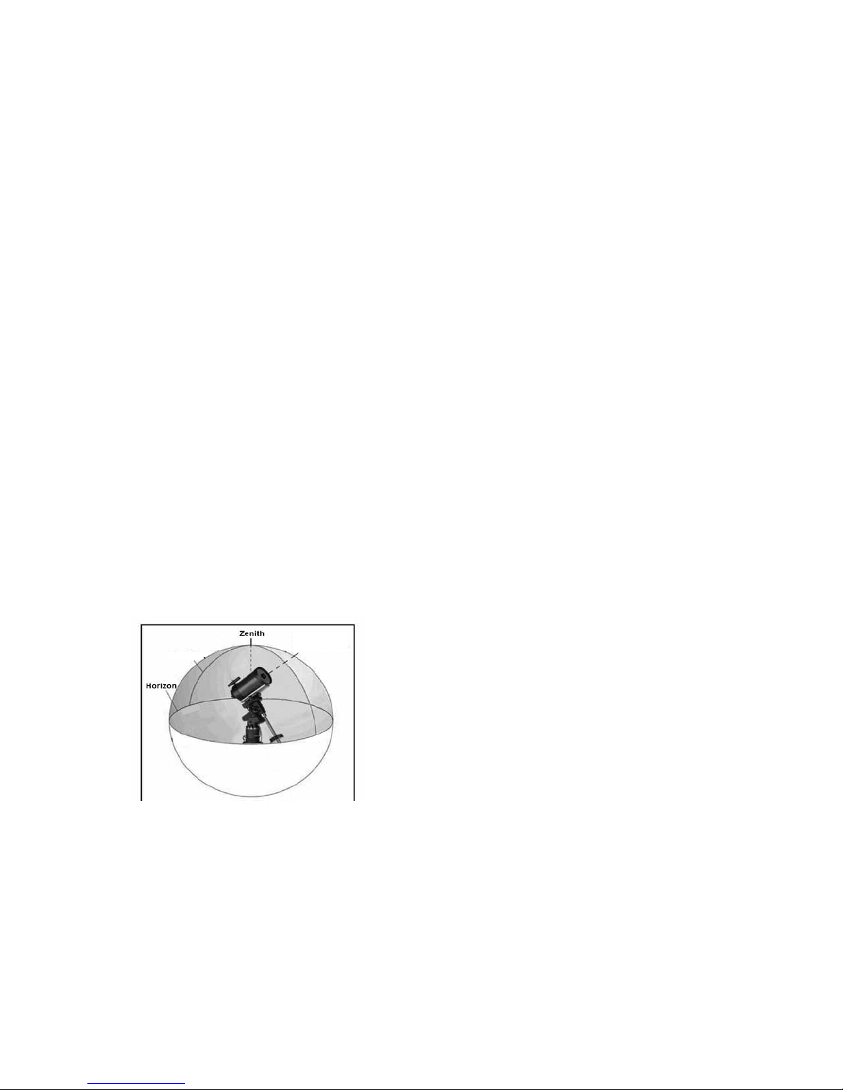
posé de ce côté du ciel (méridien) comparé aux étoiles
d’alignement originales. Cela est essentiel pour le processus de calibration précis de la monture.
Enfin, vous pouvez choisir d’ajouter plus d’étoiles de calibrations ou appuyer sur RETOUR pour mettre fin au processus.
Remarque : Filtrage Est/Ouest – pour garantir les meil-
leures performances de pointage sur ciel total,
votre monture électronique filtre et sélectionne
automatiquement ses étoiles d’alignement initiales de manière à ce que les deux premières
étoiles d’alignement se trouvent d’un côté du
méridien et que toute autre étoile se trouve à
l’opposé du méridien, comme indiqué par les
lettres « O » et « E » dans le coin supérieur
droit de l’écran LCD. Le filtrage Est/Ouest
peut être modifié en appuyant sur le bouton
MENU à tout moment pendant le processus
d’alignement.
Astuces pour l’ajout d’étoiles de calibration:
• Bien que pour l’observation de divertissement, les étoiles
de calibration supplémentaires ne soient pas nécessaires, il est recommandé d’en ajouter autant que possible pour obtenir une précision de pointage optimale.
• Les étoiles de calibrations proches de l’équateur céleste
sont plus adéquates que celles situées près des pôles
célestes.
• Bien que les étoiles de calibration ne soient pas nécessaires si la monture n’a pas été déplacée depuis
l’alignement/la calibration initial, il pourrait être nécessaire
d’effectuer la calibration de nouveau si le tube optique à
été déplacé pour quelque raison que ce soit.
Pôle Nord
Méridien
Céleste
prêt » apparaisse.
2. Appuyer sur le bouton MENU et utiliser les flèches Haut
et Bas pour sélectionner le Menu Utilitaires. Appuyer sur
ENTRÉE.
3. Utiliser les touches de défilement Haut/Bas pour sélectionner Menu Soleil et appuyer sur ENTRÉE.
4. Appuyer sur ENTRÉE de nouveau pour permettre au
Soleil d’apparaitre dans l’afficheur du contrôle manuel.
L’affichage du Soleil peut être désactivé selon le même
processus.
Astuce : Pour améliorer la précision de pointage du téle-
scope, vous pouvez utiliser la fonction Réalignement tel que décrit ci-dessous.
Alignement rapide
L’alignement rapide utilise les informations de date et d’heure
saisies au démarrage pour aligner le télescope. Cependant, au lieu d’orienter vers des étoiles d’alignement pour le
centrage et l’alignement, le télescope n’utilise qu’une étoile
pour modéliser le ciel selon les informations saisies. Cela
vous permettra d’orienter vers les coordonnées d’objets
brillants comme la Lune et des planètes et donnera au
télescope l’information nécessaire pour suivre les objets
dans toute partie du ciel (selon la précision de l’alignement
polaire). Alignement rapide n’est pas destiné à être utilisé
pour localiser de petits objets ou objets de faible intensité du
ciel profond ou pour suivre précisément des objets pour être
photographiés.
Pour utiliser Alignement rapide, sélectionnez simplement
Alignement rapide dans la liste des options d’alignement et
appuyez sur ENTRÉE. Le télescope utilisera automatiquement les paramètres de date et d’heure pour s’aligner sur le
ciel et affichera le message Aligné avec succès.
Remarque : Une fois Alignement rapide effectué. Vous
pouvez utiliser la fonction Réalignement (plus
loin dans cette section) pour améliorer la
précision de pointage du télescope.
Sud
Remarque : Méridien – Une ligne de référence imaginaire
dans le ciel qui commence au pôle Nord céleste et se termine au pôle Sud céleste et passe par le zénith. Si vous êtes
face au sud, le méridien commence à partir de votre horizon
sud et passe directement au-dessus du pôle Nord céleste.
Pour des raisons de sécurité, le Soleil ne sera pas affiché
dans aucune liste d’objet de client dans le contrôle à moins
que ce ne soit activé à partir du Menu Utilitaires. Pour permettre au Soleil d’apparaitre dans la commande manuelle,
faire ce qui suit :
1. Appuyer sur RETOUR jusqu’à ce que « Advanced VX
Nord
Dernier alignement
La méthode Dernier alignement chargera automatiquement
les dernières positions d’index mémorisées pour continuer
à utiliser l’alignement effectué lorsque le télescope à été
éteint pour la dernière fois. Cette fonctionnalité est utile par
exemple en cas de perte d’alimentation accidentelle.
Remarque : A l’instar de l’Alignement rapide, vous pouvez
utiliser la fonction Réalignement (plus loin dans
cette section) pour améliorer la précision de
pointage du télescope après le Dernier alignement. Pour maintenir un niveau de précision
plus précis sur plusieurs sessions d’observation,
utilisez la fonctionnalité de mise en veille décrite
plus loin dans ce chapitre.
Réalignement
La monture possède une fonction de réalignement qui vous
permet de remplacer la(les) étoile(s) d’alignement avec une
nouvelle étoile ou objet céleste. Cela peut être utile dans
certaines situations:
FRANÇAIS I 13
Page 46

• Si vous observez depuis quelques heures, vous remarquerez que vos deux étoiles d’alignement originales se sont
déplacées vers l’ouest de manière importante. (Rappelezvous que les étoiles se déplacent à une vitesse de 15° par
heure). Aligner sur une nouvelle étoile dans la partie est du
ciel améliorera la précision de pointage, spécialement sur
des objets dans cette partie du ciel.
• Si vous avez aligné votre télescope en utilisant la méthode
Alignement rapide, vous pouvez utiliser le réalignement
pour aligner vers un objet maintenant visible dans le ciel.
Cela améliorera la précision de pointage de votre télescope sans avoir à entrer d’information supplémentaire.
• Si vous avez utilisé la fonction d’alignement polaire assistée par ordinateur et avez déplacé la monture manuellement, il pourrait être nécessaire d’effectuer la procédure
d’alignement de nouveau.
Pour remplacer une étoile d’alignement existante avec une
nouvelle étoile d’alignement:
1. Sélectionner l’étoile souhaitée (ou objet) de la base de
données et orienter vers celui-ci.
2. Centrer avec soin l’objet dans l’oculaire.
3. Une fois centré, appuyer sur RETOUR pour revenir au
menu principal.
4. Une fois le message Advanced VX affiché, appuyez sur
ALIGNER pour sélectionner une étoile d’alignement
parmi les options disponibles.
5. L’afficheur vous demandera alors quelle étoile
d’alignement vous désirez remplacer. Utilisez les touches
de défilement HAUT et BAS pour sélectionner l’étoile
d’alignement à remplacer, et appuyez sur ENTRÉE. Il est
préférable de remplacer l’étoile la plus proche du nouvel
objet. Cela espacera vos étoiles d’alignement à travers
le ciel.
6. Appuyer sur ALIGN pour effectuer la modification.
Catalogue des objets
Sélectionner un objet
Dès que le télescope est aligné correctement, vous pouvez
sélectionner un objet dans n’importe quel catalogue de la
base de données du contrôle manuel NexStar+. Le bloc de
commande comporte une touche dédiée à chaque catégorie d’objets contenus dans sa base de données: Système
Solaire, étoiles et objets du ciel profond.
• Système Solaire – Le catalogue Système Solaire affich-
era toutes les planètes (et la Lune) dans notre Système
Solaire qui sont actuellement visibles dans le ciel. Pour
activer l’affichage du soleil comme objet sélectionnable
dans la base de données, reportez-vous à l’option Soleil
du menu Télescope.
• Étoiles – Le catalogue Étoiles affiche une liste person-
nalisée des étoiles les plus brillantes, étoiles doubles
(binaires), étoiles variables et astérismes spécifiques.
• Ciel Profond – Le catalogue Ciel Profond affiche une
liste des meilleures Galaxies, Nébuleuses et amas
d’étoiles, ainsi que le Messier complet et objets NGC.
Il y a également une liste alphabétique de tous les
objets du ciel profond en ordre de leur nom commun.
Utilisez les touches de DÉFILEMENT pour défiler à travers
les catalogues afin de trouver l’objet que vous désirez voir.
Lors d’un défilement à travers une longue liste d’objets,
maintenir enfoncé le bouton HAUT ou BAS vous permettra
de défiler plus rapidement à travers le catalogue.
Pivoter vers un objet
Dès que l’objet sélectionné est affiché sur l’écran du contrôle
manuel, vous avez deux options:
• Appuyer sur le bouton INFO OBJET. Cela vous don-
nera de l’information utile sur l’objet sélectionné tel que
magnitude, constellation et information supplémentaire sur
les objets les plus populaires.
• Utilisez les flèches HAUT/BAS pour défiler à travers
l’info de l’objet sélectionné.
• Utiliser le bouton RETOUR pour retourner à la base de
données objets.
• Appuyer sur le bouton ENTRÉE. Cela fera orienter le
télescope vers les coordonnées de l’objet affiché sur le
contrôle manuel. Tandis que le télescope s’oriente vers
l’objet, l’utilisateur peut toujours accéder à plusieurs
fonctions du contrôle manuel (tel qu’afficher l’information
sur l’objet).
REMARQUE: Les catalogues Messier, NGC et SAO né-
cessitent l’entrée d’une désignation numérique. Dès que vous avez sélectionné le bouton correspondant au catalogue en question
et sélectionné le catalogue Messier, NGC
ou SAO, vous verrez un curseur clignotant
indiquant que vous être en mode d’entrée
numérique. Entrer le numéro de catalogue
pour l’objet que vous désirez voir. Appuyez
sur ENTRÉE pour faire orienter le télescope
vers l’objet, ou maintenir enfoncé le bouton
OPTION (logo Celestron) et appuyer sur
INFO OBJET pour consulter l’information
sur l’objet sélectionné.
Attention: Ne faites jamais pivoter le télescope
lorsque quelqu’un est entrain de regarder dans
l’oculaire. Le télescope peut se déplacer à haute
vitesse et des blessures pourraient en résulter.
Bouton SkyTour
La monture Advanced VX offre une fonction de visite qui
permet à l’utilisateur de choisir un objet intéressant dans
une liste construite selon la date et l’heure à laquelle vous
observez. La visite automatique affichera seulement les
objets contenus dans le catalogue et selon les limites du
filtre personnalisé. Pour activer la fonction visite, appuyez
sur SKY TOUR sur le bloc de commande.
1. Appuyez sur le bouton SKY TOUR du contrôle manuel.
2. Utilisez les touches de DEFILEMENT pour sélectionner
A ne pas rater cette nuit.
3. La monture Advanced VX pivotera automatiquement en
azimut par rapport à sa position d’origine, ce qui aidera à
14 I FRANÇAIS
Page 47

éviter l’enroulage du câble d’alimentation durant la visite.
4. Le contrôle manuel affichera les meilleurs objets à observer qui sont présentement dans le ciel.
• Pour obtenir de l’information et données sur l’objet af-
fiché, appuyez sur INFO OBJET. Appuyez une fois pour
afficher les coordonnées de l’objet. Appuyez dessus de
nouveau pour afficher le texte descriptif. Appuyez sur
RETOUR pour revenir à l’écran précédent.
• Pour orienter vers l’objet afficher, appuyer sur ENTRÉE.
• Pour voir le prochain objet de la visite guidée, appuyer
sur BAS.
Bouton d’identification
Appuyez sur le bouton IDENTIFIER pour rechercher dans
le catalogue des bases de données de la monture et afficher
les noms et distances angulaires des objets correspondants
les plus proches, en relation avec la position actuelle. Cette
fonction peut être utile dans deux cas. Tout d’abord, elle peut
permettre d’identifier un objet non identifié contenu dans le
champ de l’oculaire. De plus, le mode Identification peut être
utilisé pour trouver d’autres objets célestes qui sont proches
des objets observés.
Par exemple, si votre télescope est pointé sur l’étoile la plus
brillante de la constellation de la Lyre, choisir Identification la nommera à coup sûr comme Vega. Mais, la fonction Identification effectuera aussi une recherche dans le
catalogue NGC et bases de données du Système Solaire
et affichera toute planète ou objet du ciel profond dans son
environnement proche. Dans cet exemple, la nébuleuse en
anneau (M57) serait affichée comme se trouvant à environ 6°
de distance.
La luminosité et proximité des objets affichés peuvent être
définies à l’aide du filtre Identification dans Configuration du
télescope.
Touches de direction
Le contrôle manuel contient quatre touches de direction
situées au centre de celui-ci qui contrôlent le déplacement
du télescope en altitude (haut et bas) et azimut (gauche
et droite). La vitesse de mouvement peut être définie en 9
vitesses.
1 = 2x 6 = .3° / sec
2 = 4x 7 = 1° / sec
3 = 8x 8 = 2° / sec
4 = 16x 9 = 4° / sec
5 = 32x
Vitesse des moteurs
Le bouton MOTOR SPEED (12) vous permet de modifier
immédiatement la vitesse de mouvement des servomoteurs
sur une plage allant de « Haute vitesse » à « Précision ».
Chaque taux correspond à un numéro du pavé numérique.
9 est la vitesse la plus élevée (approximativement 4 ° par
seconde, selon la source d’alimentation) et est utilisé pour
le mouvement entre les objets et étoiles d’alignement. Le
numéro 1 est la vitesse la plus lente (2x sidéral) et peut être
utilisé pour un centrage précis des objets dans l’oculaire.
Pour modifier la vitesse des moteurs:
• Appuyez sur le bouton VITESSE DU MOTEUR sur le contrôle manuel. L’écran LCD affichera la vitesse actuelle.
• Appuyer sur le numéro du contrôle manuel qui correspond
à la vitesse désirée.
Le contrôle manuel a une caractéristique « bouton double
» qui permet d’accélérer la vitesse des moteurs sans avoir
à spécifier la vitesse. Pour utiliser cette caractéristique, appuyer simplement sur la flèche qui correspond à la direction
d’orientation désirée du télescope. Tout en maintenant ce
bouton appuyé, pressez la direction opposée. Ceci accélérera le pivot à la vitesse maximum.
Lorsque vous utilisez les e HAUT et BAS du contrôle contrôle manuel, les taux les moins élevés (6 et moins) déplacent
les moteurs dans la direction opposée de celle utilisée pour
les taux les plus élevés (7 - 9). Ceci est mis en place pour
faire en sorte qu’un objet se déplace dans la direction appropriée lorsque vous observez par l’oculaire (par ex., appuyez
sur le bouton haut déplacera l’étoile vers le haut lorsque dans
le champ de vision de l’oculaire). Mais, si vous utilisez l’un
des taux de pivot les moins élevés (6 et moins) pour effectuer
le centrage dans le starpointer, alors vous devrez utiliser les
touches de la direction opposée.
Touche Aide
Dans les mises à jour futures du micrologiciel, ce bouton offrira
des astuces de dépannage. Pour l’instant, est utilisé comme
raccourci au catalogue Messier.
Touche de menu
La monture Advanced VX contient plusieurs fonctions
de réglage définies par l’utilisateur conçues pour donner le contrôle des différentes fonctions du télescope à
l’utilisateur. Toutes les fonctions et outils peuvent être
atteints en appuyant sur MENU et en faisant défiler pour
choisir les options ci-dessous.
Menu Suivi
Mode Suivi – cela permet de choisir la manière dont le
télescope suit un objet selon le type de monture utilisée pour
supporter le télescope. Le produit possède trois différents
modes de suivi :
• EQ Nord – Pour suivre le ciel lorsque le télescope est
aligné dans l’hémisphère nord.
• EQ Sud – Pour suivre le ciel lorsque le télescope est
aligné dans l’hémisphère sud.
• Désactivé – Lors de l’utilisation du télescope pour observation terrestre (terrain) le pistage peut être désactivé afin
que le télescope ne bouge pas.
Taux de suivi – En plus d’être capable de déplacer le
télescope avec les touches du contrôle manuel, votre télescope suivra continuellement un objet céleste alors qu’il se
déplace dans le ciel nocturne. La vitesse de suivi peut être
définie selon le type de l’objet concerné:
• Sidérale – Cette vitesse compense pour la rotation de
FRANÇAIS I 15
Page 48

la terre en déplaçant le télescope à la même vitesse de
rotation de la terre, mais en direction opposée. Lorsque le
télescope est aligné polairement, cela peut être possible
en effectuant un mouvement vertical seulement.
• Lunaire – Utilisé pour pister la Lune lors d’observation de
paysage lunaire.
• Solaire – Utilisé pour pister le Soleil lors d’observation
solaire en utilisant un filtre solaire adéquat.
Menu Afficher heure-site
Ce menu permet d’afficher l’heure actuelle et la longitude
et latitude téléchargées depuis le récepteur GPS optionnel
SkySync. Cette option affichera également d’autres
informations relatives à l’heure et à l’emplacement telles
que le fuseau horaire, l’heure d’été et l’heure sidérale
locale. L’heure sidérale locale (LST) est utile pour connaître
l’ascension droite des objets célestes qui se trouvent sur le
méridien à ce moment. L’option Afficher heure-site affiche
toujours la dernière heure et emplacement saisie pendant la
connexion avec le GPS. Une fois les informations actualisées
reçues, alors celles-ci seront mises à jour sur l’écran. Si le
GPS est éteint ou non présent, alors le contrôle manuel
n’affichera que la dernière heure et emplacement saisis en
dernier.
Menu du contrôle manuel
Le menu « Contrôle manuel » vous permet de personnaliser
certaines caractéristiques du contrôle manuel NexStar+.
Pour accéder à ce menu, appuyez sur le bouton MENU (#7
sur le pavé numérique) et utilisez les touches de défilement
pour sélectionner « Contrôle manuel » puis appuyez sur ENTRÉE. Utilisez les touches de défilement pour choisir l’une
des options suivantes :
• Éclairage des touches : Pour régler de manière in-
dépendante l’éclairage des touches et de l’écran LCD.
• Menu de Défilement : Pour régler la vitesse à laquelle
les mots défilent sur l’écran LCD.
• Activer les caractères gras : Pour modifier le format
de police des caractères affichés à l’écran entre normal
et gras.
• Contraste : Utilisez les touches de défilement pour régler
le contraste de l’écran LCD.
• Langage : Pour modifier le langage d’affichage de l’écran
LCD.
Remarque: L’option de langage peut également s’afficher
lors de la première utilisation du contrôle
manuel. Cette option peut également être
affichée en maintenant le bouton Option (le
logo Celestron) pendant 10 secondes pendant
l’allumage du télescope.
Fonctionnalités de Réglage de Télescope
Réglage Heure-Site – Permet à l’utilisateur de person-
naliser l’affichage du télescope en modifiant les paramètres
d’heure et d’emplacement (tel que le fuseau horaire et heure
avancée).
Anti-rebond – Tous les engrenages mécaniques ont un
certain rebond ou jeu entre les engrenages.Ce jeu est
évident par le temps que prend l’étoile à se déplacer dans
l’oculaire lorsque les flèches du contrôle manuel sont appuyées (spécialement lors de changement de directions). La
fonction anti-rebond de l’Advanced VX permet à l’utilisateur
de compenser le rebond en entrant une valeur qui rappelle
rapidement aux moteurs d’éliminer le jeu entre les engrenages. Le montant de compensation nécessaire dépend de
la vitesse de rotation sélectionnée; plus la vitesse de rotation
est lente plus cela prendra de temps pour que l’étoile apparaisse dans l’oculaire. Chaque axe possède deux valeurs,
une positive et une négative :
• La valeur positive est la quantité de compensation appliquée lorsque vous appuyez sur un bouton pour que les
engrenages bougent rapidement.
• La valeur négative est la quantité de compensation appliquée lorsque vous relâchez le bouton, tournant les
engrenages dans le sens opposé pour continuer le suivi.
Normalement, chaque mesure doit être identique. Vous
devrez expérimenter avec différentes valeurs (de 0 à 99) ;
une valeur entre 20 et 50 est normalement suffisante pour la
plupart des observations visuelles, alors qu’une valeur plus
élevée peut être nécessaire pour le guidage photographique.
Pour régler la valeur anti-rebond, défiler vers le bas vers l’option
anti-rebond et appuyer sur ENTRÉE. Observez un objet par
l’oculaire et observez la vitesse de réponse de chaque pression des quatre touches. Prenez note de quels mouvements
observent une pause entre la pression sur le bouton et son
déclenchement. Testez un axe à la fois, réglez la valeur antirebond de manière à ce que le mouvement soit aussi immédiat
que possible sans pour autant créer un soubresaut lorsque le
bouton est appuyé et relâché. Ensuite, saisissez la même valeur
pour les positions positives et négatives. Si vous remarquez
un soubresaut lorsque le bouton est relâché, mais remarquez
une pause lorsque la valeur est réduite, utilisez la plus haute
valeur en positif et la plus faible valeur en négatif. Le télescope
gardera en mémoire ces valeurs et les utilisera à chaque mise
sous tension ou jusqu’à ce qu’elles soient modifiées.
Limites de Filtre – Lorsqu’un alignement est terminé, le télescope sait automatiquement quels objets célestes se trouvent
au-dessus de l’horizon. En conséquence, lors du défilement à
travers les listes de base de données (ou en sélectionnant la
fonction Visite Guidée), le contrôle manuel affichera seulement
les objets qui se trouvent au-dessus de l’horizon au moment
de l’observation. Vous pouvez personnaliser la base de données d’objets en sélectionnant les limites d’altitude qui sont
appropriés à votre emplacement et situation. Par exemple, si
vous faites de l’observation dans un emplacement montagneux
où l’horizon est partiellement obscurci, vous pouvez fixer votre
limite minimum d’altitude pour qu’elle lise +20°. Cela fera en
sorte que la commande manuelle n’affichera que les objets qui
sont supérieurs en altitude à 20°.
Astuce : Si vous souhaitez explorer la totalité de la base de
données d’objets, définissez l’altitude maximum
sur 90° et la limite minimum sur -90°. Cela permettra d’afficher chaque objet présent dans la base de
données, qu’il soit visible ou non.
Touches de direction – La direction dans laquelle une
étoile semble se déplacer dans l’oculaire est fonction de la
position du tube du télescope par rapport au méridien. Cela
peut être problématique, particulièrement si vous effectuez
16 I FRANÇAIS
Page 49

des photos astronomiques. Pour compenser, la direction
des clés de contrôle du moteur peut être modifiée. Pour
renverser la logique du contrôle manuel, appuyer sur MENU
et sélectionner Direction Buttons du menu Utilitaires. Utilisez
les touches haut et bas (10) pour sélectionner soit l’azimut
(ascension droite) ou altitude (déclinaison) puis appuyez sur
ENTRÉE. Sélectionnez soit positif ou négatif pour chaque
axe puis appuyez sur ENTRÉE pour enregistrer. Définir la
direction de bouton azimut en positif ne déplacera pas le
télescope dans la même direction que le suivi du télescope
(par exemple vers l’est). Définir les touches d’altitude en
positif ne déplacera pas le télescope dans le sens inverse
des aiguilles d’une montre sur l’axe de DECLINAISON.
Approche Aller à – Permet à l’utilisateur le soin de définir
la direction du télescope lors de l’orientation vers un objet.
Cela permet à l’utilisateur de minimiser les effets de rebond
lors de la rotation d’un objet à un autre. Comme dans le cas
des touches de direction, définir Approche Aller à en positif
fera en sorte que le télescope effectuera une approche sur
un objet dans la même direction que le suivi (ouest) pour
l’azimut et dans le sens inverse des aiguilles d’une montre
pour la déclinaison. La déclinaison Approche Aller à ne sera
valable que si le tube du télescope est d’un côté du méridien. Une fois que le tube passe de l’autre côté du méridien,
l’Approche Aller à devra être inversée.
Pour modifier la direction d’Approche Aller à, simplement
sélectionner Approche Aller à du menu Configuration du télescope, sélectionner soit l’approche Altitude soit l’approche
Azimut, puis choisir positif ou négatif et enfin appuyer sur
ENTRÉE.
Astuce : Pour minimiser les effets négatifs du rebond
d’engrenage sur la précision de pointage, le paramètre
de direction de bouton doit idéalement être similaire au
réglage Approche Aller à. Par défaut, les touches de direction haut et bas pour centrer sur les étoiles d’alignement
élimineront la majorité de l’effet de rebond dans les
engrenages. Si vous modifiez le réglage Approche Aller à,
il n’est pas nécessaire de modifier également les touches
de direction. Prenez simplement note de la direction dans
laquelle le télescope se déplace lorsqu’il termine son Approche Aller à finale. Si le télescope approche son étoile
d’alignement depuis l’ouest (azimut négatif), et dans le
sens des aiguilles d’une montre (altitude négative), alors
veillez à ce que le centrage sur les étoiles d’alignement
s’effectue dans la même direction dans le télescope.
Taux d’autoguidage – Permet à l’utilisateur de définir un
taux d’autoguidage comme pourcentage de taux sidéral.
Cela est utile lorsque vous calibrez votre télescope en
tant qu’autoguideur pour l’imagerie astronomique à longue
exposition.
Orientation OTA – Certains utilisateurs pourraient vouloir
utiliser un adaptateur de barre de tandem qui permet d’attacher
deux tubes optiques à la monture simultanément. Lorsque
les barres de tandem les plus courantes sont installées, les
tubes optiques sont à angle de 90° comparé à la configuration
standard. Pour pouvoir aligner la monture avec les étoiles de
manière correcte, celle-ci doit savoir qu’une barre de tandem
est utilisée, et dans quelles directions le ou les tubes sont
alignés (est ou ouest) avant de commencer la procédure.
L’option de tandem doit être définie avant de commencer toute
étape de l’alignement sur les étoiles. Pour ce faire, rendez-vous
dans les Options du télescope, sélectionnez l’option Tandem
puis appuyez sur ENTRÉE. Choisissez ensuite parmi l’une des
options suivantes:
• Est – Si les tubes installés sont orientés vers l’est lorsque
les marques d’index de déclinaison sont alignés, sélectionnez Est.
• Ouest – Si les tubes installés sont orientés vers l’ouest
lorsque les marques d’index de déclinaison sont alignées,
sélectionnez Ouest.
• Normal – Si la barre de tandem n’est plus utilisée, sélec-
tionnez l’option « Normal » pour désactiver la fonctionnalité.
Méridien – Cette fonction permet à la monture de se
comporter correctement lorsqu’il s’agit de pivoter vers des
objets accessibles depuis chaque côté du méridien. La
fonctionnalité Méridien permet au télescope de rester sur
un côté spécifique de la monture pendant son pivotement,
et ainsi de continuer à suivre selon les limites R.A. définies
par l’utilisateur. Voir limites R.A. ci-dessous. Le fonctionnalité
Méridien offre quatre choix:
• Courant favori – Permet à la monture d’utiliser le côté ac-
tuel en priorité lorsqu’elle s’oriente vers des objets proches
du méridien. Par exemple, si votre limite d’orientation R.A.
est définie pour permettre à la monture de suivre à 10°
après le méridien, alors le télescope restera sur le côté actuel du méridien pour s’orienter vers des objets se trouvant
au maximum à 10° après le méridien.
• Favoriser l’ouest – Si l’objet cible est accessible
depuis chaque côté de la monture, sélectionner l’option «
Favoriser l’ouest » fait en sorte que la monture pointe vers
l’objet comme si celui-ci se trouvait à l’ouest du méridien.
Le tube sera donc positionné sur le côté est de la monture,
et pointera vers l’ouest.
• Favoriser l’est – Si l’objet cible est accessible depuis
chaque côté de la monture, sélectionner l’option « Favoriser l’est » fait en sorte que la monture pointe vers l’objet
comme si celui-ci se trouvait à l’est du méridien. Le tube
sera donc positionné sur le côté ouest de la monture, et
pointera vers l’est.
• Désactivé – Ceci est l’option par défaut, qui donne l’ordre
à la monture de pivoter vers le côté opposé pour voir les
objets se trouvant sur le côté opposé du méridien. Mais,
une fois l’objet désiré atteint, la monture continuera à pivoter plus loin que le méridien selon les limites d’orientation
R.A. définies.
Réglages de monture – Une fois les réglages de la
monture calibrés (voir la section Utilitaires ci-dessous), les
valeurs sont enregistrées et affichées sur le contrôle manuel.
Il est déconseillé de modifier les valeurs de calibration. Mais
chaque paramètre peut être modifié si nécessaire pour améliorer les performances du télescope.
• Valeur de cône – Ceci est la valeur d’erreur de cône
définie lorsque les opérations Utilitaires/Calibration de
monture/Interrupteur DEC sont effectuées.
• Index DEC – Ceci est la valeur d’erreur d’index de
déclinaison enregistrée lorsque les étoiles de calibration
sont ajoutées après l’alignement sur les étoiles original.
FRANÇAIS I 17
Page 50
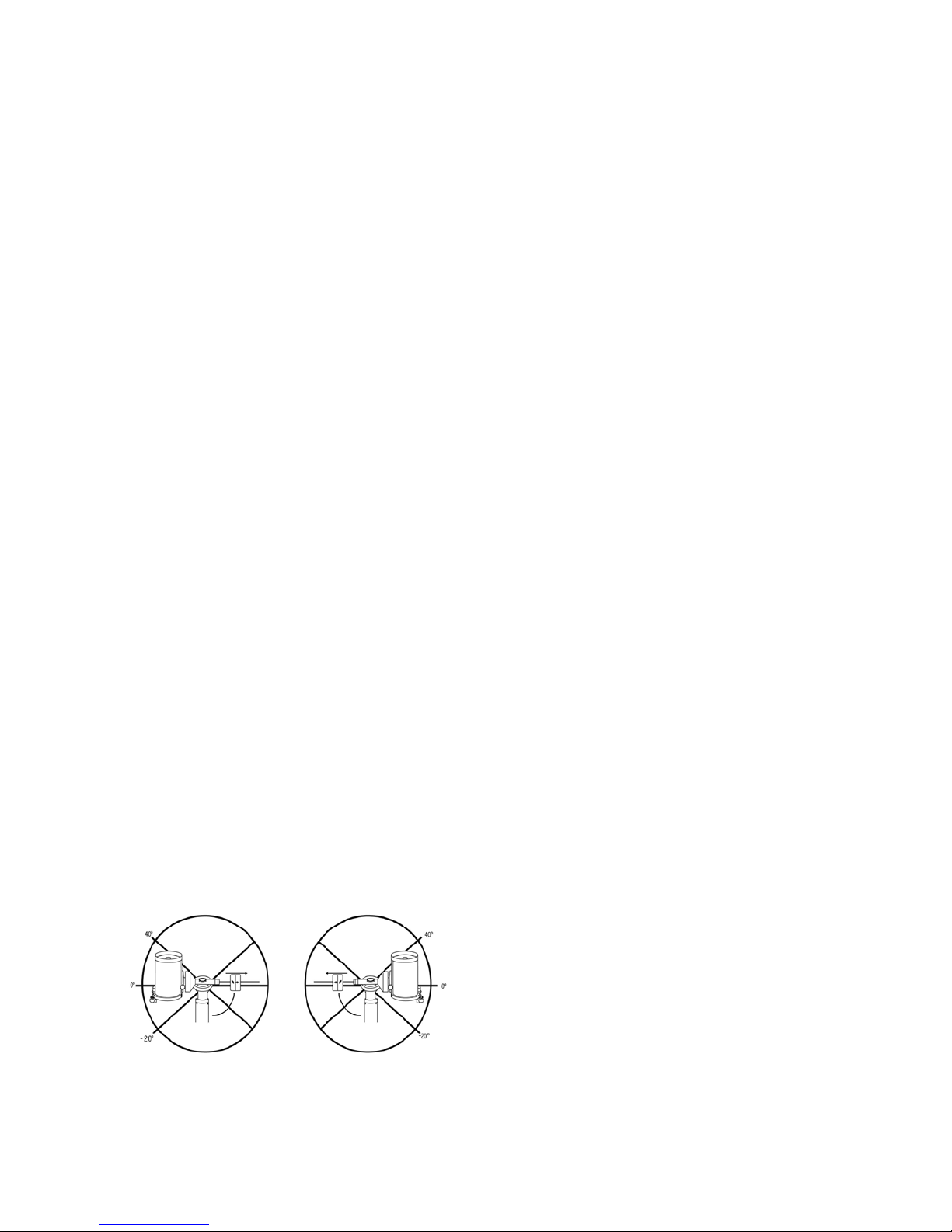
• R.A. (Ascension Droite) Index – Ceci est la valeur
d’erreur d’index R.A. définie lorsque les opérations Utilitaires/Calibration de monture/R.A. sont effectuées.
R.A. (Ascension Droite) Limites – Permet de définir
les limites du télescope au sein desquelles le télescope
peut s’orienter ou suivre en ascension droite (R.A.) avant
de s’arrêter. Les limites d’orientation sont représentées en
degrés et sont par défaut définies sur 0°, qui est la position
du télescope lorsque la barre de contrepoids est étendue
horizontalement. Mais, cette limite peut être définie selon vos
besoins spécifiques. Par exemple, si vous utilisez un équipement d’imagerie CCD (Dispositif à transfert de charge) qui
est équipé de câbles qui sont trop courts pour permettre
au télescope de pivoter pour couvrir la totalité du ciel, vous
pouvez définir la limite d’orientation de la monture comme
désiré. La monture cessera de pivoter avant d’atteindre ce
point. Ou si vous prenez une image d’un objet situé juste
après le méridien, alors vous pouvez définir cette limite
pour permettre à la monture de continuer à suivre dans la
même direction après le méridien sans avoir à « basculer »
le télescope sur le côté opposé de la monture (consultez la
fonctionnalité Méridien exposée ci-dessus.) Selon le premier
exemple donné ci-dessous, l’utilisateur pourrait faire pivoter
le télescope en R.A. (azimut) jusqu’à ce qu’il atteigne le
point de tension des câbles maximum. Ensuite, observez la
position azimutale du télescope (en vous reportant à l’option
Obtenir la position axiale dans le menu Utilitaires), vous pouvez déterminer la position du télescope en azimut dans sa
position la plus étendue. Saisissez cette valeur d’azimut dans
les champs d’orientation azimutale maximum et minimum
pour garantir que le télescope ne se déplacera plus loin que
ce point. Les limites d’orientation du télescope peuvent être
définies pour que le télescope s’arrête n’importe où entre
les angles 40° au dessus et 20° au dessous. Pour définir les
limites d’orientation R.A., sélectionnez les options suivantes:
• R.A. (Ascension Droite) Limite est – Saisissez un nom-
bre entre +40 o et -20 o pour définir la limite d’orientation
lorsque le tube est situé du côté est de la monture.
• R.A. (Ascension Droite) Limite ouest – Saisissez
un nombre entre +40 o et -20 o pour définir la limite
d’orientation lorsque le tube est situé du côté ouest de la
monture.
• Désactiver limites – Cela permet d’ignorer toute valeur
précédemment saisie et permet donc à la monture de
suivre au maximum passé le méridien (donc -20° de
chaque côté).
Est Ouest
Avertissement : Pour permettre au télescope de se déplacer vers une étoile depuis la direction qui limite la quantité
de rebond dans les engrenages, il pourrait être nécessaire
de faire en sorte que le télescope s’oriente plus loin que les
limites d’orientation saisie pour approcher l’étoile depuis la
direction correcte. Cela pourrait limiter votre capacité à effectuer l’orientation vers un objet de 6° par rapport à la limite
d’orientation R.A. définie dans le contrôle manuel. Si cela
est un problème, la direction que le télescope utiliser pour
centrer un objet peut être modifiée. Pour modifier la direction
d’orientation du télescope, rendez-vous dans l’option Approche aller à du menu de Réglage du télescope.
Taux personnalisé 9 – Cela vous permet de personnaliser la vitesse à laquelle la monture s’oriente vers une cible.
Vous pouvez alors définir les axes R.A. et DEC. de manière
individuelle.
Menus Utilitaires
Parcourez le MENU (9) pour avoir accès à une variété
d’options utilitaires avancées du télescope, comme Calibration de la monture, Hibernation et bien d’autres encore.
Calibration de la monture – Pour optimiser les performances et la précision de pointage du télescope, la monture
est possède des routines de calibration lui permettant de
compenser les variations mécaniques communes à toute
monture équatoriale Allemande. Chaque calibration est complètement automatique et dans la majorité des cas ne doit
être effectuée qu’une fois. Nous recommandons fortement
de prendre le temps d’effectuer la calibration de monture.
• R.A. (Ascension Droite) Basculement – Cette procé-
dure enregistre la marge d’erreur de décalage lorsque la
marque d’index d’ascension droite est alignée au démarrage. Calibration de R.A. L’index améliorera la précision
de votre alignement d’origine pour les alignements du
télescope dans le futur.
• Calibration Aller à – La calibration aller à est un outil
utile lorsqu’on fixe de lourds accessoires photographiques
au télescope. La calibration aller à calcule la distance et
le temps nécessaire à la monture pour compléter son
orientation finale Aller à lors de l’orientation vers un objet.
La modification de l’équilibre du télescope peut prolonger
le temps d’orientation complet. La calibration Aller à tient
compte de tous les déséquilibres et modifie la distance
Aller à pour compenser.
Position d’origine – La position d’« origine » est une position personnalisable qui est utilisée pour ranger le télescope
lorsqu’il est inutilisé. La position d’origine est utile lorsque le
télescope est rangé dans une installation d’observation permanente. Par défaut la position d’Origine est la même que la
position d’index utilisée lorsque l’alignement de la monture
est effectué.
Pour définir la position d’Origine de votre monture, utilisez
simplement les touches fléchées du contrôle manuel pour
orienter la monture dans la position désirée. Sélectionnez
l’option Définir et appuyez sur Entrée.
Sélectionnez l’option Aller à pour remettre le télescope en
position d’Origine à tout moment.
Réglage d’Usine – Réinitialise le contrôle manuel au
réglage d’usine original. Les paramètres tels que valeurs de
compensation de rebond, date et heure initiales, longitude/
latitude ainsi que les limites de filtre et d’orientation seront
18 I FRANÇAIS
Page 51

réinitialisées. Cependant, les paramètres stockés tels que
les objets définis par l’utilisateur resteront intacts même si
Réglage d’Usine est sélectionné. Le contrôle manuel vous
demandera d’appuyer sur la clé «0» avant de revenir au
réglage d’usine par défaut.
Version – Cette option vous permet de voir la version
courante du contrôle manuel et du logiciel de contrôle du
moteur. Le premier ensemble de numéros indique la version
du logiciel du contrôle manuel. Pour le contrôle de moteur, la
commande manuelle affichera deux ensembles de numéros;
les premiers numéros sont pour l’azimut et les deuxièmes
pour l’altitude.
Obtenir Position de l’Axe – Affiche l’altitude et azimut relatives pour l’emplacement actuel du télescope.
Aller à position de l’axe – Vous permet d’entrer une position spécifique d’altitude et d’azimut et ensuite de l’orienter
vers ces cordonnées.
Hibernation – Hibernation permet au télescope d’être hors
tension et de quand même retenir son alignement lors de la
mise sous tension. Cela ne fait pas qu’épargner de l’énergie,
mais est idéal pour ceux laissent leur télescope monté en tout
temps ou qui laissent leur télescope en un emplacement pour
une longue période de temps. Pour placer votre télescope en
mode Hibernation :
1. Sélectionner Hibernation du Menu Utilitaires.
2. Déplacer le télescope à l’emplacement souhaité et appuyer sur ENTRÉE.
3. Éteignez le télescope. Se rappeler de ne jamais déplacer
votre télescope manuellement en étant en mode
Hibernation.
Dès que le télescope est de nouveau sous tension,
l’afficheur devrait indiquer Réveil. Après avoir appuyé sur
ENTRÉE, vous avez l’option de défiler à travers l’information
d’heure/site pour confirmer le réglage actuel. Appuyer sur
ENTRÉE pour réveiller le télescope.
Astuce: Appuyer sur RETOUR à l’écran Réveil vous permettra d’explorer les différentes fonctions du contrôle manuel
sans avoir à sortir le télescope de son mode d’hibernation.
Pour réveiller le télescope après avoir appuyé sur RETOUR,
sélectionnez Hibernation du menu Utilitaires et appuyez sur
ENTRÉE. Ne pas utiliser les touches de direction pour orienter le télescope en mode hibernation.
Menu Soleil
Pour des raisons de sécurité, le Soleil ne sera pas affiché
en tant qu’objet de base de données à moins qu’il ne soit
auparavant activé. Pour activer le Soleil, aller au menu Sun
et appuyer sur ENTRÉE. Le Soleil sera alors affiché dans le
catalogue des Planètes et pourra être utilisé en tant qu’objet
d’alignement lors de l’utilisation de la méthode d’alignement
Système Solaire. Pour retirer le Soleil de l’affichage du contrôle manuel, encore une fois sélectionner le menu Soleil du
menu des Utilitaires et appuyer sur ENTRÉE.
Réglage de Position de monture
L’option Position de monture peut être utilisée pour maintenir votre alignement si vous devez desserrer les jambes
ou situation similaire. Par exemple, cette fonction est utilise
si vous devez équilibrer la monture de nouveau après avoir
effectué un alignement. Pour définir la position de la mon-
ture, effectuez un pivot vers une étoile brillante de la liste
des étoiles nommées, et sélectionnez Définir la Position de
monture. Le contrôle manuel se synchronisera sur l’étoile
en vous demandant de centrer l’étoile dans l’oculaire et en
appuyant sur la touche Aligner. Une fois la synchronisation
effectuée, vous pouvez déplacer la monture sur les deux
axes pour l’équilibrer. Une fois prêt à orienter le télescope
vers votre prochain objet, souvenez-vous de centrer l’étoile
brillante précédemment utilisée dans l’oculaire avec précision. Cet outil rendra invalide l’index PEC.
Activer/désactiver le GPS – Si vous utilisez votre télescope avec l’accessoire facultatif SkySync GPS, il sera
nécessaire d’activer le GPS lors de la première utilisation
de celui-ci. Si vous désirez utiliser la base de données du
télescope pour trouver les coordonnées d’un objet céleste
à une date passée ou future, vous devrez désactiver le
module GPS afin d’être en mesure d’entrer manuellement
la date et heure autre que celle courante.
Activer/désactiver RTC (Horloge en temps réel) –
Permet d’activer ou non l’horloge interne en temps réel du
télescope. Pendant l’alignement, le télescope reçoit toujours
les informations mises à jour en temps réel de la RTC Si
vous désirez utiliser la base de données contrôle manuel
pour trouver les coordonnées d’un objet céleste à une date
passée ou future, vous devrez désactiver la RTC afin d’être
en mesure d’entrer manuellement la date et heure autre que
celle courante.
Correction d’erreur périodique (PEC) – PEC est conçue
pour améliorer la qualité d’imagerie en réduisant l’amplitude
des erreurs introduites par la vis sans fin et ainsi améliorer
la précision du mouvement. Cette fonctionnalité est conçue
pour l’astrophotographie avancée et est utilisée lorsque votre
télescope est aligné correctement polairement. Pour plus
d’informations sur comment utiliser la PEC, reportez-vous à
la section du manuel concernant l’« Astrophotographie ».
Menu des Objets personnalisés
L’appareil peut mémoriser jusqu’à 400 objets personnalisés
différentes en mémoire. Les objets peuvent être des objets
terrestres de jour ou un objet céleste intéressant que vous
avez découvert et qui n’est pas inclus dans la base de données régulière. Il y a plusieurs manières de conserver un
objet en mémoire dépendant du type d’objet:
Aller à l’objet: Pour aller à un objet défini par l’utilisateur
stocké dans la base de données, défiler vers la bas vers «
Aller à objet céleste » ou « Aller à objet terrestre » et entrer le
numéro de l’objet que vous désirez sélectionner et appuyer
sur ENTRÉE. La commande manuelle récupérera automatiquement et affichera les coordonnées avant de s’orienter
vers l’objet.
Enregistrer objet céleste: Votre télescope stocke les
objets célestes dans sa base de données en sauvegardant
son ascension droite et sa déclinaison dans le ciel. De cette
manière le même objet peut être localisé chaque fois que
le télescope est aligné. Dès que l’objet souhaité est centré
dans l’oculaire, simplement défiler vers la commande « Enregistrer objet céleste » et appuyer sur ENTRÉE. L’afficheur
vous demandera d’entre un nombre entre 1 et 1200 pour
identifier l’objet. Appuyez sur ENTRÉE de nouveau pour
conserver cet objet dans la base de données.
FRANÇAIS I 19
Page 52

Conserver objet
• de base de données : Cette fonction vous permet de
créer votre propre visite guidée d’objets de base de données en vous permettant d’enregistrer la position courante
du télescope et d’enregistrer le nom de l’objet en sélectionnant un des catalogues de base de données. Ces
objets peuvent être retrouvés en sélectionnant Aller à
objet céleste.
• Saisir Ascension Droite - Dec : Vous pouvez également
stocker un ensemble de coordonnées spécifiques d’un
objet en entrant l’ascension droite et la déclinaison pour
cet objet. Défiler vers la commande «Enter RA-DEC» et
appuyer sur ENTRÉE. L’afficheur vous demandera d’entrer
en premier l’ascension droite et la déclinaison de l’objet
souhaité.
• Conserver objet terrestre : Le télescope peut égale-
ment être utilisé comme une lunette d’observation pour les
objets terrestres. Les objets terrestres fixes peuvent être
stockés en conservant leur altitude et azimut relativement à
l’emplacement du télescope au moment de l’observation.
Étant donné que ces objets dépendent de l’emplacement
du télescope, ils ne sont valides que pour cet emplacement seulement. Pour enregistrer des objets terrestres,
centrer l’objet souhaité dans l’oculaire. Défiler vers le bas à
la commande « Enregistrer objet terrestre » et appuyez sur
ENTRÉE. L’afficheur vous demandera d’entre un nombre
entre 1 et 1200 pour identifier l’objet. Appuyer sur ENTRÉE de nouveau pour conserver cet objet dans la base
de données.
Pour remplacer le contenu de tout objet défini par l’utilisateur,
simplement sauvegarder un nouvel objet en utilisant l’un des
numéros d’identification existant ; le télescope remplacera le
précédent objet défini par l’utilisateur par le nouvel objet.
Obtenir Ascension Droite et Déclinaison - Affiche
l’ascension droite et déclinaison pour l’emplacement actuel du
télescope.
DEC. - Vous permet d’entrer une ascension droite spécifique
et déclinaison et de l’orienter vers celle-ci.
Astuce: Pour enregistrer un ensemble de coordonnées
(R.A. /Dec.) de manière permanente dans la base de
données, enregistrez-le comme Objet personnalisé
comme décrit ci-dessus.
Identification
Le mode Identification recherchera dans les listes
ou catalogues de la base de données de la monture
et affichera le nom et distances décalées des objets
correspondants le plus proches. Cette fonction peut être
utile dans deux cas. Tout d’abord, elle peut permettre
d’identifier un objet non identifié contenu dans le champ de
l’oculaire. De plus, le mode Identification peut être utilisé
pour trouver d’autres objets célestes qui sont proches des
objets observés. Par exemple, si votre télescope est pointé
vers l’étoile la plus brillante de la constellation Lyra, en
choisissant le mode Identification et ensuite en cherchant
dans le catalogue Étoile Nommée retournera sans aucun
doute l’étoile Véga comme étoile que vous observez
actuellement. Cependant, en sélectionnant le mode
Identification et en cherchant dans le catalogue Messier
ou Objet Nommé, le contrôle manuel vous indiquera que
la Nébuleuse de l’Anneau (M57) se trouve à 6° de votre
position présente. En cherchant dans le catalogue Étoiles
Binaires, vous remarquerez qu’Epsilon Lyrae se trouve à 1°
de Véga. Pour utiliser la fonction Identification :
• Appuyer sur la touche Menu et sélectionner l’option Identification.
• Utiliser les touches de défilement Haut/Bas pour sélectionner le catalogue à rechercher.
• Appuyez sur ENTRÉE pour débuter la recherche.
Remarque : Quelques-unes des bases de données
contiennent des milliers d’objets, et cela
pourrait prendre une minute ou deux avant
que l’objet le plus près soit affiché.
Aller à précis
La monture possède une fonction Aller à précise qui peut
vous aider à trouver les objets très pâles et effectuer le
centrage sur un objet précis pour l’astrophotographie. Aller
à précis recherche automatiquement l’étoile brillante la plus
proche de l’objet désiré et demande à l’utilisateur d’effectuer
le centrage de l’oculaire avec précision. Le contrôle manuel
calcule ensuite la petite différence entre la position Aller à et
sa position centrée. En utilisant cette différence, la monture s’oriente ensuite sur l’objet désiré avec une précision
améliorée.
Pour utiliser Aller à précis :
1. Appuyer sur le bouton MENU et utiliser les flèches Haut
et Bas pour sélectionner Aller à précis.
• Choisissez la base de données pour sélectionner l’objet
que vous désirez observer depuis son contenu ou;
• Choisissez R.A. /DEC. pour saisir les coordonnées
célestes vers lesquelles s’orienter.
2. Une fois l’objet désiré sélectionné, le contrôle manuel
recherchera puis affichera l’étoile la plus proche de votre
objet désiré. Appuyez sur ENTRÉE pour orienter vers la
planète brillante d’alignement.
3. Utilisez les touches de direction pour centrer l’étoile
d’alignement avec précision dans l’oculaire.
4. Appuyez sur ENTRÉE pour orienter vers l’objet désiré.
20 I FRANÇAIS
Page 53

Arbre du menu principal Advanced VX
Menu
Suivi Mode EQ Nord
EQ Sud
Désactivé
SidéralTaux
Solaire
Lunaire
Afficher heure-site
Contrôle manuel
Obtenir R.A.-DEC
Aller à R.A.-DEC
Site enregistré
Contrôle du ré-
troéclairage
Menu de Défilement
Activer les caractères gras
Contraste
Langue d’interface
Se reporter au schéma - Page suivanteRéglage du Télescope
Se reporter au schéma - Page suivanteUtilitaires
Aller à des objets célestesObjets personnalisés
Enregistrer objet céleste
Enregistrer objet BdD
Saisir R.A. et DEC
Aller à objet terrestre
Enregistrer objet terrestre
Éclairage du clavier
Éclairage de l’affichage
Identification
Aller à précis
FRANÇAIS I 21
Page 54

Arbre du menu principal Advanced VX
Réglage du Télescope
Saisie Heure-Site
Anti-rebond
Limites de filtre
Touches de direction
Approche aller à
Taux d’autoguidage
Orientation OTA
Méridien
Site personnalisé
Base de données de
villes
R.A. positive
R.A. négative
DEC. positive
DEC. négative
Bouton R.A
Bouton DEC
Approche R.A.
Approche DEC.
Taux R.A.
Taux DEC.
Normal
Est
Ouest
Désactivé
Utilitaires
Calibrer la monture
Position d’Origine
Réglage d’usine
Version
Obtenir position d’axe
Aller à position d’axe
Hibernation
Menu Soleil
Réglage de Position de Monture
Activer ou désactiver le GPS
Activer ou désactiver RTC
PEC
Aller à
Définir
Réglages de monture
Limites R.A.
Taux personnalisé 9
Courant favori
Favoriser l’ouest
Favoriser l’est
Valeur de cône
Définir limite R.A. est
Définir limite R.A. ouest
Désactiver limites
Axe R.A. Activé
Définir taux
Axe DEC. Activé
Définir taux
22 I FRANÇAIS
Page 55

Assemblage de tube optique
Selon le kit de télescope acheté, l’un des tubes optiques est peut-être livré. Cette section du manuel vous expliquera
comment installer les types les plus courants.
Kit N°. 22020 32054 32062 12031
Conception optique Lunette Newtonien Newtonien Edge HD
Diamètre 6” (150mm) 6” (150mm) 8” (200mm) 8” (203mm)
Distance focale 1200mm f/8 750mm f/5 1000mm f/5 2032mm f/10
Oculaire 20mm (60x) -
1.25” (3,1 cm)
Chercheur 9x50 6x30 9x50 9x50
Diagonale en étoile 90”- 1.25”
(228,5 cm- 3,1 cm)
Monture Advanced VX Advanced VX Advanced VX Advanced VX
Trépied 2” (5 cm) en acier
inoxydable
Contrepoids 2 x 12 lbs (5,5 Kg) 1x 12 lbs (5,5 Kg) 2x 12 lbs (5,5 Kg) 1x 12 lbs (5,5 Kg)
Longueur du tube 51” (128 cm) 27” (69 cm) 27” (69 cm) 17” (43 cm)
Poids du tube 19 lb (8,6 Kg) 10 lb (4,5 Kg) 14 lb (6,3 Kg) 13 lb (5,8 Kg)
Kit N°. 12025 12079 12026 12046
Conception optique Schmidt-Cassegrain Schmidt-Cassegrain Schmidt-Cassegrain Schmidt-Cassegrain
Diamètre 5” (125mm) 6” (150mm) 8” (203mm) 9-1/4” (235mm)
Distance focale 1250mm f/10 1500mm f/10 2032mm f/10 2350mm f/10
Oculaire 25mm (50x) - 1.25” 20mm (75x) - 1.25” 25mm (81x) - 1.25” 25mm (94x) - 1.25”
StarPointer 6x30 6x30 6x30 6x30
Diagonale en étoile 90”- 1.25”
(228,5 cm- 3,1 cm)
Monture Advanced VX Advanced VX Advanced VX Advanced VX
Trépied 2” (5 cm) en acier
inoxydable
Contrepoids 1x 12 lb (5,5 Kg) 1x 12lb (5,5 Kg) 1x 12lb (5,5 Kg) 2x 12lb (5,5 Kg)
Longueur du tube 13” (33 cm) 16” (40 cm) 17” (43 cm) 22” (56 cm)
Poids du tube 10 lb (4,5 Kg) 10 lb (4,5 Kg) 12 lb (5,5 Kg) 21 lb (9,5 Kg)
20mm (38x) -
1.25” (3,1 cm)
- - 90”- 1.25”
2” (5 cm) en acier
inoxydable
90”- 1.25”
(228,5 cm- 3,1 cm)
2” (5 cm) en acier
inoxydable
20mm (50x) -
1.25” (3,1 cm)
2” (5 cm) en acier
inoxydable
90”- 1.25”
(228,5 cm- 3,1 cm)
2” (5 cm) en acier
inoxydable
40mm (51x) -
1.25” (3,1 cm)
(228,5 cm- 3,1 cm)
2” (5 cm) en acier
inoxydable
90”- 1.25”
(228,5 cm- 3,1 cm)
2” (5 cm) en acier
inoxydable
Kit N°. 12067
Conception optique Schmidt-Cassegrain
Diamètre 11” (280mm)
Distance focale 2800mm f/10
Oculaire 40mm (70x) - 1.25”
StarPointer 9x50
Diagonale en étoile 90”- 1.25”
(228,5 cm- 3,1 cm)
Monture Advanced VX
Trépied 2” (5 cm) en acier
inoxydable
Contrepoids 3x 12lb (5,5 Kg)
Longueur du tube 24” (61 cm)
Poids du tube 28 lb (12,7 Kg)
FRANÇAIS I 23
Page 56

Installation du réfracteur (#21020)
Installation du chercheur
Pour installer le chercheur sur le télescope, celui-ci doit
être au préalable fixé au support de chercheur puis attaché
au télescope. Vers l’arrière du tube du télescope, près de
l’assemblage de renvoi coudé, se trouve un petit support
avec une vis. C’est là que le support du chercheur s’installe.
Pour installer le chercheur :
1. Faites glisser le joint circulaire par l’extrémité du chercheur et faites-le rouler aux deux tiers environ du tube.
2. Insérez l’extrémité de l’oculaire par le support jusqu’à ce
que le joint soit pressé fermement entre le chercheur et
l’intérieur du support.
Chercheur
Support du
chercheur
Support de fixation
Vis
Vis de tension du
renvoi coudé
Tube du renvoi
coudé 5 cm
Bouton de mise
au point
Adaptateur
d’oculaire 1,25
Pas de vis de
l’adaptateur
en T
Pour retirer l’oculaire, desserrez la vis sur le renvoi coudé et
retirez l’oculaire. Vous pouvez alors l’échanger avec un autre
oculaire.
Les oculaires sont en général désignés par leurs caractéristiques de distance focale et de diamètre de tube. La
distance focale est imprimée sur le tube de l’oculaire. La distance focale est inversement proportionnelle à la puissance
de l’oculaire : plus celle-ci est importante (c-à-d, plus le chiffre est élevé), moins le grossissement de l’oculaire (c-à-d. la
puissance) est réduite. Plus celle-ci est réduite (c-à-d, plus
le chiffre est faible), plus le grossissement de l’oculaire (c-àd. la puissance) est élevé. Généralement, vous utiliserez une
puissance de grossissement variant de faible à modérée
lors de vos séances d’observation.
3. Serrez les vis de réglage jusqu’à ce qu’elles entrent en
contact avec le corps du chercheur.
4. Trouvez le support de montage situé à l’arrière (ouvert)
du télescope.
5. Desserrez la vis sur le support de montage du télescope.
6. Faites glisser le support du chercheur (attaché au chercheur) dans le support de montage du télescope.
7. Le support du chercheur pourra être glissé par l’arrière.
Le chercheur doit être orienté de manière à pointer vers
l’avant (ouvert) du télescope.
8. Serrez la vis de verrouillage sur le support de montage
pour fixer le chercheur en place.
Installation des oculaires
L’oculaire est l’élément optique qui grossit l’image focalisée
par le télescope. Sans l’oculaire, il serait impossible d’utiliser
le télescope visuellement. L’oculaire s’adapte directement
dans le renvoi coudé. Pour fixer l’oculaire:
1. Desserrez les vis de l’adaptateur de l’oculaire de manière
à ce qu’elle ne pénètre pas dans la surface intérieure
du tube.
2. Faire glisser la portion en chrome de l’oculaire dans le
renvoi coudé.
3. Serrez la vis pour fixer l’oculaire en place.
Votre télescope à réfraction peut utiliser des oculaires de
diamètres 3,1 cm et 5 cm indifféremment. Avant d’installer
un oculaire de 5 cm, vous devrez au préalable désinstaller
l’adaptateur 3,1 cm. Pour ce faire, desserrez simplement
les deux vis à main qui se trouvent autour du renvoi coudé
et retirez l’adaptateur d’un pouce et quart. Une fois fait, un
accessoire de 5 cm peut être inséré directement dans le
renvoi coudé avec les deux vis à main.
Votre télescope est livré avec une diagonale en étoile de
3,1 cm. La diagonale peut être insérée dans l’extrémité de
l’adaptateur 3,1 cm, qui vous permet d’utiliser des oculaires
de 3,1 cm à un angle plus agréable lorsque vous observez
près du zénith.
Installation du réflecteur Newtonien
(#32054 & #32062)
Installation du chercheur
Pour installer le chercheur sur le télescope, celui-ci doit être
au préalable être fixé au support de chercheur puis attaché
au télescope. Vers l’avant du tube du télescope, près de
l’assemblage de renvoi coudé, se trouve un petit support
avec une vis. C’est là que le support du chercheur s’installe.
Pour installer le chercheur :
1. Faites glisser le joint circulaire par l’extrémité du chercheur et faites-le rouler aux deux tiers environ du tube.
2. Insérez l’extrémité de l’oculaire par le support jusqu’à ce
24 I FRANÇAIS
Page 57

que le joint soit pressé fermement entre le chercheur et
l’intérieur du support.
3. Serrez les vis de réglage jusqu’à ce qu’elles entrent en
contact avec le corps du chercheur.
4. Trouvez le support de montage situé à l’avant (ouvert) du
télescope.
5. Desserrez la vis sur le support de montage du télescope.
6. Faites glisser le support du chercheur (attaché au chercheur) dans le support de montage du télescope.
7. Le support du chercheur pourra être glissé par l’arrière.
Le chercheur doit être orienté de manière à pointer vers
l’avant (ouvert) du télescope.
8. Serrez la vis de verrouillage sur le support de montage
pour fixer le chercheur en place.
Installation des oculaires
L’oculaire est l’élément optique qui grossit l’image focalisée par le télescope. Sans l’oculaire, il serait impossible
d’utiliser le télescope visuellement. L’oculaire s’adapte
directement dans l’adaptateur d’oculaire. Pour fixer un
oculaire:
1. Desserrez les vis de l’adaptateur de l’oculaire de manière
à ce qu’elle ne pénètre pas dans la surface intérieure du
tube.
2. Faire glisser la portion en chrome de l’oculaire dans
l’adaptateur d’oculaire.
3. Serrez la vis pour fixer l’oculaire en place.
devrez au préalable désinstaller l’adaptateur 3,1 cm et ainsi
pouvoir installer l’oculaire de 5 cm. Pour ce faire, desserrez
simplement les deux vis à main chromées qui se trouvent
autour du renvoi coudé et retirez l’adaptateur d’un pouce
et quart. Une fois fait, un oculaire de 5 cm peut être inséré
directement dans le renvoi coudé et fixé avec les deux vis
à main.
Installation des tubes optiques EdgeHD
et Schmidt-Cassegrain (#12031, #12079,
#12025, #12026, #12046 and #12067)
Installer la diagonale en étoile
Le renvoi coudé dévie la lumière à angle droit du chemin
de lumière du télescope. Lors de l’observation du ciel, cela
vous permet d’être installé plus confortablement que si vous
deviez regarder directement dans l’axe du tube. Pour installer
la diagonale en étoile dans le tube optique:
1. Desserrez la vis de l’adaptateur d’optique jusqu’à ce que
celle-ci ne rentre plus (c-a-d n’obstrue pas) le diamètre
interne de celui-ci.
2. Faire glisser la portion en chrome de la diagonale en
étoile dans l’adaptateur d’optique.
3. Serrer la vis sur le barillet de mise au point afin de
maintenir en place la diagonale en étoile.
Oculaire
Portion en chrome
Adaptateur d’oculaire
Oculaire
Pour retirer l’oculaire, desserrez la vis à main de
l’adaptateur d’oculaire et retirez l’oculaire. Vous pouvez
alors l’échanger avec un autre oculaire. Les oculaires sont
en général classés selon leur longueur focale, qui est
imprimée sur le côté de l’oculaire. Plus importante est la
longueur de focale (c-à-d, plus le chiffre est élevé), moins
le grossissement de l’oculaire est puissant. Plus courte est
la longueur de focale (c-à-d, plus le chiffre est élevé), plus
le grossissement de l’oculaire est puissant. Généralement,
vous utiliserez une puissance de grossissement variant de
faible à modérée lors de vos séances d’observation.
Si vous possédez un tube optique Newtonien de 20,3 cm
(#32062), votre télescope peut accueillir des oculaires de
3,1 cm et 5 cm. Avant d’installer un oculaire de 5 cm, vous
Diagonale
en étoile
Adaptateur d’optique
Si vous désirez modifier l’orientation de la diagonale en
étoile, déserrez la vis située sur l’adaptateur optique pour
permettre le pivot de la diagonale en étoile. Faites pivoter la
diagonale en étoile comme désiré puis resserrez la vis
à main.
Installation de l’oculaire
L’oculaire est l’élément optique qui grossit l’image focalisée
par le télescope. L’oculaire peut s’installer directement dans
l’adaptateur d’optique ou dans la diagonale en étoile. Pour
installer l’oculaire :
1. Desserrer la vis sur la diagonale en étoile pour qu’elle ne
bloque pas le diamètre interne de l’extrémité de l’oculaire
de la diagonale.
2. Glissez la partie chromée de l’oculaire basse puissance
dans la diagonale en étoile.
3. Serrez la vis sur la diagonale en étoile pour fixer l’oculaire
en place.
FRANÇAIS I 25
Page 58

Pour retirer l’oculaire, desserrez la vis de la diagonale en
étoile et retirez l’oculaire. Vous pouvez alors l’échanger avec
un autre oculaire (vendu séparément).
Les oculaires sont en général désignés par leurs caractéristiques de distance focale et de diamètre de tube. La
distance focale est imprimée sur le tube de l’oculaire. Plus
importante est la longueur de focale (c-à-d, plus le chiffre
est élevé), moins le grossissement de l’oculaire est puissant.
Plus courte est la longueur de focale (c-à-d, plus le chiffre
est élevé), plus le grossissement de l’oculaire est puissant.
Généralement, vous utiliserez une puissance de grossissement variant de faible à modérée lors de vos séances
d’observation, Pour obtenir plus d’informations sur comment déterminer la puissance, voyez la section « Calculer
l’agrandissement ».
Installation du chercheur 6x30
Les télescopes Schmidt Cassegrain 12.7, 15.2, 20.3 et
23.5 cm sont livrés avec des chercheurs 6x30 vous aidant
à trouver et à centrer des objets dans votre télescope. Pour
faire cela, le chercheur comporte une croix de visée intégrée
qui indique le centre optique du chercheur. Pour installer
le chercheur :
1. Attachez le support du tube optique. Pour ce faire, placez
la portion incurvée du support dans la fente située au
dessus des deux trous de la cellule arrière. Le support
devrait être orienté de manière à ce que les anneaux qui
maintiennent le chercheur soient sur le tube du télescope,
pas la cellule arrière. Commencez à visser les vis à la
main puis terminez avec un tournevis.
Chercheur
Vis de réglage de nylon
Support du chercheur
Cellule arrière
2. Vissez partiellement les trois vis à main qui maintiennent le
chercheur en place dans le support. Serrez les vis jusqu’à
ce que les têtes de nylon soient presque à l’intérieur du
diamètre du support. Ne PAS les visser complètement,
car cela interférerait avec l’installation du chercheur. (Il est
cependant plus facile d’installer les vis avant d’installer le
chercheur).
3. Faites glisser le joint en anneau depuis l’arrière du chercheur (il ne pourra PAS être installé depuis le côté de
l’objectif). Il pourrait être nécessaire de le détendre légèrement. Une fois sur le corps principal du chercheur,
faites-le glisser d’environ un pouce depuis l’extrémité
du chercheur.
4. Faites pivoter le chercheur jusqu’à ce qu’une croix de
visée soit parallèle à l’axe R.A. et que l’autre est
perpendiculaire à l’axe DEC.
5. Faites glisser l’extrémité de l’oculaire dans l’avant
du support.
6. Serrez légèrement les trois vis de nylon à main sur
l’anneau avant du support de chercheur.
7. Une fois cela fait, repoussez le joint en anneau jusqu’à ce
qu’il soit fermement installé dans l’anneau arrière du support de chercheur.
8. Serrez les trois vis à pointe de nylon à la main jusqu’à ce
qu’elles soient fermement insérées.
Installation du chercheur 9x50
Les télescopes EdgeHD 20,3 cm et Schmidt-Cassegrain 11”
sont livrés avec des chercheurs 9x50 vous aidant à trouver et
à centrer des objets dans votre télescope. Pour faire cela, le
chercheur comporte une croix de visée intégrée qui indique le
centre optique du chercheur. Le chercheur doit d’abord être
installé dans le support de retrait rapide avant d’être attaché à
la cellule arrière du télescope. Pour installer le chercheur :
1. Repérez le support de montage du chercheur situé sur
la partie inférieure du support de chercheur. Desserrez
les deux vis à main situées sur les côtés du support de
montage du support du chercheur.
2. Repérez les deux trous situés sur la cellule arrière du
télescope dans la partie supérieure gauche, lorsque vous
regardez depuis l’arrière du tube.
3. Placez le support de montage sur les deux trous situés
sur la cellule arrière du tube optique.
4. Insérez les vis dans le support dans la cellule arrière.
AVERTISSEMENT : Si vous retirez le support de montage,
ne pas revisser les vis complètement dans la cellule arrière du
télescope. Les vis pourraient être assez longues pour gêner le
mouvement, et même endommager le miroir principal.
Une fois le support fermement installé, vous êtes prêt à attacher le support du chercheur.
1. Faites glisser le joint en anneau par l’extrémité arrière du
tube vers l’objectif du chercheur.
2. Faites glisser l’extrémité du côté objectif du chercheur
dans l’anneau avant du support (l’anneau avant est celui
comportant les vis de réglage), puis dans l’anneau arrière.
Il pourrait être nécessaire de pousser la vis de pivot à
ressort pour permettre au chercheur de passer dans
l’anneau arrière.
3. Une fois cela fait, repoussez le joint en anneau jusqu’à ce
qu’il soit fermement installé dans l’anneau arrière du support de chercheur.
4. Serrez les vis d’alignement à main jusqu’à ce qu’elles
entrent en contact avec le corps du chercheur.
Vis de pivot
Vis
d’alignement
Vis de retrait rapide
26 I FRANÇAIS
Page 59

Alignement du chercheur
Le chercheur peut être réglé à l’aide de deux vis de réglage,
situées sur le dessus et sur la droite (en regardant dans le
chercheur) du support du chercheur et une vis de pivot à
ressort (sur la gauche du support). Cela permet de tourner
la vis du dessus pour contrôler l’élévation du chercheur et
de tourner la vis de réglage droite pour régler sa position
horizontalement. La vis à ressort permet de faire en sorte que
le chercheur soit toujours en contact avec les vis de réglage.
Pour rendre le processus d’alignement plus aisé, vous pouvez
effectuer cette opération de jour, quand il est plus simple de
localiser votre cible. Pour aligner le chercheur:
1. Sélectionnez un objet en évidence qui est éloigné de
vous de plus d’un mile. Cela permet d’éliminer les effets
de parallaxe entre le télescope et le chercheur.
2. Pointez votre télescope vers l’objet sélectionné et
centrez-le dans les optiques du télescope.
3. Resserrez les leviers de verrouillage d’azimut et d’altitude
pour fixer le télescope en position.
4. Vérifiez dans le chercheur que l’objet est bien en vue.
5. Réglez les vis à main jusqu’à ce que le viseur soit centré
sur l’objet.
Retrait du capuchon de lentille
Les télescopes EdgeHD et Schmidt-Cassegrain sont équipés d’un capuchon de lentille avec mécanisme de verrouillage en baïonnette. Pour retirer le capuchon, tenez le corps
de celui-ci fermement et faites pivoter sa bordure extérieure
d’un demi-pouce dans le sens des aiguilles d’une montre
pour le retirer.
Alignement polaire de la monture
Balances de latitude
La manière la plus simple d’aligner polairement le télescope
est avec une balance de latitude. A la différence des autres
méthodes qui requièrent que vous trouviez le pôle céleste
en identifiant certaines étoiles qui lui sont proches, cette
méthode utiliser un point constant connu pour déterminer
à quelle altitude l’axe polaire doit être pointé. La monture
Advanced VX peut être réglée de 7 à 77 degrés.
La constante, mentionnée ci-dessus est la relation entre
votre latitude et la distance angulaire du pôle céleste avec
l’horizon nord (ou sud) ; la distance angulaire entre l’horizon
nord et le pôle céleste nord est toujours égale à votre
latitude. Pour illustrer ceci, imaginez que vous-vous tenez
sur le Pôle nord, latitude +90°. Le pôle nord célest, qui est
d’une déclinaison de +90° se situerait donc juste au dessus
de vous (en d’autres termes, à 90° au dessus de l’horizon).
Maintenant, imaginons que vous-vous déplacez d’un degré
vers le sud - votre latitude est maintenant de +89° et le pôle
céleste n’est donc plus exactement au dessus de vous. Il
s’est rapproché d’un degré vers l’horizon nord. Cela veut dire
que le pôle est maintenant à 89° au dessus de l’horizon nord.
Si vous-vous déplacez d’un degré en plus, la même chose se
reproduit. Vous devez vous déplacer de 70 miles vers le sud
ou le nord pour modifier votre latitude d’un degré. Comme
vous pouvez le constater depuis cet exemple, la distance
entre l’horizon nord et le pôle céleste est constamment égale
à votre latitude.
Si vous faites l’observation depuis Los Angeles, qui est
d’une latitude de 34°, alors le pôle céleste se trouve à 34°
au dessus de l’horizon. Une balance de latitude ne fait alors
que pointer l’axe polaire du télescope sur l’élévation correcte au dessus de l’horizon nord (ou sud). Pour effectuer
l’alignement de votre télescope:
1. Veillez à orienter l’axe polaire de la monture vers le nord.
Utilisez un repère du paysage dont vous connaissez
l’orientation comme référence.
2. Mettez la monture à niveau. La monture est équipée d’un
niveau à bulle pour ce faire.
3. Réglez l’altitude de la monture jusqu’à ce que
l’indicateur de latitude soit pointé vers votre latitude.
Déplacer la monture aura un impact sur l’angle dans
lequel l’axe polaire est orienté. Pour en savoir plus sur
comment régler la monture équatoriale, reportez-vous à
la section « Réglage de la monture ».
Cette méthode peut être effectuée pendant la journée,
pour éviter d’avoir à le faire dans l’obscurité. Bien que
cette méthode ne vous oriente PAS directement vers
le pôle, elle permet de limiter le nombre de corrections
futures nécessaires pour le suivi d’un objet. Cela sera
FRANÇAIS I 27
Page 60

également assez précis pour permettre la mise au point
initiale pour la photographie planétaire (quelques
secondes) et l’astrophotographie à exposition courte
(quelques minutes).
Alignement polaire à l’aide du contrôle manuel
La monture Advanced VX comporte une fonction
d’alignement polaire appelée « Toute-étoile » qui vous
aidera à aligner votre télescope pour une précision de suivi
améliorée et l’astrophotographie. Cette fonctionnalité vous
permet de choisir n’importe quelle étoile d’alignement pour
aider à aligner la monture de votre télescope avec précision sur le pôle nord céleste. Avant d’utiliser la fonction
d’alignement polaire, le télescope doit être grossièrement
pointé vers le nord et devrait être aligné avec trois étoiles
dans le ciel. Reportez-vous à la section « Échelle de latitude
» pour vous aider à trouver le nord et régler la latitude de
la monture.
Une fois votre télescope aligné avec deux étoiles au
minimum et une étoile de calibration, faites pivoter votre télescope vers n’importe quelle étoile brillante de la base de
données des Étoiles nommées. Pour obtenir les meilleurs
résultats possibles, choisissez une étoile d’alignement polaire qui est haute dans le ciel et proche du méridien. Évitez
autant que possible les étoiles qui sont trop proches des
horizons est/ouest, juste au dessus de vous ou proches
du pôle céleste. Une fois terminé, appuyez sur le bouton
d’alignement et utilisez les touches haut/bas du contrôle
manuel pour sélectionner Alignement polaire dans la liste.
Aligner la monture – Une fois l’alignement à deux étoiles et
une étoile de calibration effectué, et votre télescope orienté
vers une étoile brillante de la base de données, sélectionnez
« Aligner la monture ». Le télescope s’éloignera et reviendra
sur la même étoile.
1. Le contrôle manuel vous demandera de recentrer l’étoile
dans le chercheur et appuyez sur ENTRÉE.
2. Le contrôle manuel vous demandera de centrer l’étoile
avec précision dans le chercheur et appuyez sur ALIGNER. Le télescope sera alors « synchronisé » avec cette
étoile et pivotera pour pointer sur la position de l’étoile s’il
est correctement aligné polairement.
Remarque : Pour obtenir l’alignement le plus précis possible, il est conseillé d’utiliser un oculaire réticulaire ou
grande puissance pour centrer l’étoile avec précision dans
le champ de vision.
3. Utilisez les réglages de latitude et d’azimut pour placer
l’étoile au centre de l’oculaire. Ne pas utiliser les touches
de direction du contrôle manuel pour positionner l’étoile.
Une fois l’étoile centrée dans l’oculaire, appuyez sur
ENTRÉE. L’axe polaire devrait maintenant être pointé vers
le pôle céleste nord.
Mettre à jour votre alignement des étoiles
Une fois l’alignement polaire effectué, il est en général
conseillé de confirmer la précision de pointage du télescope
pour voir l’impact que le mouvement de la monture a eu.
Puisque l’alignement polaire nécessite la « synchronisation »
du télescope sur une étoile brillante avant de commencer. Il
pourrait être nécessaire d’annuler la synchronisation avant de
réaligner. Pour annuler la synchronisation :
• Appuyez sur le bouton d’alignement et utilisez les touches
haut/bas du contrôle manuel pour sélectionner Annuler
synchro. dans la liste. Le message Terminé s’affichera sur
l’écran.
Pour réaligner votre télescope :
1. Faites pivoter le télescope vers l’une des étoiles
d’alignement originelles ou autre étoile brillante si les
étoiles d’alignement d’origine ne sont plus disponibles
depuis votre site actuel. Appuyez sur le bouton Aligner
et utilisez les touches haut/bas du contrôle manuel pour
sélectionner Étoiles d’alignement dans la liste.
2. Le contrôle manuel vous demandera laquelle des étoiles
à remplacer. Utilisez les touches de défilement Haut/Bas
pour sélectionner l’étoile désirée et appuyez sur Entrée.
3. Centrer l’étoile de nouveau dans le chercheur et appuyer
sur Entrée.
4. Centrer l’étoile dans l’oculaire et appuyer sur Aligner.
5. Répéter la procédure pour la seconde étoile d’alignement.
Pour une meilleure précision de pointage sur le ciel en entier,
il est conseillé d’aligner au moins une étoile de calibration située sur le côté opposé du méridien. Pour ajouter des étoiles
de calibration :
1. Faites pivoter le télescope vers une étoile brillante située
du côté opposé du méridien comparé à vos deux étoiles
d’alignement.
2. Appuyez sur le bouton Aligner et utilisez les touches haut/
bas du contrôle manuel pour sélectionner Étoiles de
calibration dans la liste.
3. Alignez l’étoile dans le chercheur puis dans l’oculaire
comme vous l’avez fait précédemment avec les étoiles
d’alignement.
Afficher alignement – l’utilisateur peut maintenant afficher la marge d’erreur d’alignement polaire sur les axes
R.A. et DEC. Ces valeurs permettent de voir la précision
avec laquelle la monture est pointée vers le pôle céleste
et avec quelle précision l’utilisateur a effectué l’alignement
des étoiles avec le contrôle manuel et le réglage de la
monture. Pour afficher la marge d’erreur d’alignement:
• Appuyez sur le bouton Aligner et utilisez les touches haut/
bas du contrôle manuel pour sélectionner Afficher alignement dans la liste puis appuyez sur Entrée.
Photographie longue exposition à foyer principal
Ceci est la dernière forme d’astrophotographie à tenter une
fois les autres maîtrisées. Elle est conçue pour les objets
du ciel profond, c’est à dire ceux qui se trouvent hors de
notre système solaire, ce qui inclut les amas d’étoiles,
nébuleuses et galaxies. Bien qu’il semble logique d’utiliser
un grossissement puissant pour observer ces objets,
l’opposé est vrai. La majorité de ces objets couvrent de
larges régions angulaires et rentrent aisément dans le
champ de foyer principal de votre télescope. La luminosité
de ces objets, par contre, nécessitent de longues expositions, d’où la difficulté.
Il existe plusieurs techniques pour ce type de photographie,
et voici la liste des accessoires requis pour celle que nous
avons sélectionnée. La meilleure méthode pour la longue
exposition en astrophotographie avec un guidage hors axe
optionnel. Ce dispositif vous permet de photographier et de
28 I FRANÇAIS
Page 61

guider le télescope simultanément. De plus, un anneau-T
sera requis pour attacher votre appareil photo à un guidage
hors axe optionnel
Les autres équipements requis sont un astroguideur, qui
est un petit appareil photo qui s’attache au guideur radial et
maintient l’étoile guide centrée pendant que vous effectuez
vos prises de vue. Voici un résumé bref de la technique.
1. Alignement polaire de la monture. Pour en savoir plus sur
l’alignement polaire, reportez-vous à la section Alignement
polaire plus haut dans ce manuel.
2. Retirez tout accessoire visuel.
3. Vissez le guideur radial dans votre télescope.
4. Vissez le l’anneau-T dans le guideur radial.
5. Montez le corps de votre caméra sur l’anneau-T comme
vous le feriez avec toute autre lentille.
6. Réglez la vitesse d’obturation sur « B ».
7. Effectuez la mise au point sur une étoile.
8. Centrez votre sujet dans le champ de votre appareil
photo.
9. À l’aide de votre autoguideur, repérez une étoile adaptée
dans le champ de votre télescope. Cela peut se révéler
etre la partie la plus longue du processus.
10. Ouvrez l’obturateur à l’aide d’un câble de déclencheur.
11. Surveillez votre étoile guide pendant toute la durée
d’exposition et utilisez les touches du controle manuel
pour effectuer les corrections nécessaires.
12. Fermez l’obturateur de votre appareil photo.
Correction d’erreur périodique (PEC)
La Correction d’erreur périodique, ou PEC, est un système
permettant d’améliorer la précision de suivi de la monture
en limitant le nombre de corrections nécessaires pour
garder une étoile guide centrée dans l’oculaire. PEC est
conçu pour améliorer la qualité des images en limitant
l’ampleur des erreurs de vis sans fin. L’utilisation de PEC
se fait en trois étapes. Pour commencer, l’Advanced VX
doit connaitre la position actuelle de sa vis sans fin, pour
s’en servir comme point de référence lors de la lecture
d’une erreur enregistrée. Ensuite, vous devez guider
à l’aide d’un autoguideur pendant 10 minutes, temps
pendant lequel le système enregistre les corrections que
vous effectuez. (Le temps de révolution complet de la
vis sans fin est de 10 minutes). Cela « enseigne » à la
puce PEC les caractéristiques de la vis sans fin. L’erreur
périodique de la vis sans fin sera enregistrée dans la puce
PEC et utilisée pour la correction d’erreur périodique. La
dernière étape est de rejouer les corrections effectuées
pendant la phase d’enregistrement. Gardez cependant
à l’esprit que cette fonctionnalité est conçue pour
l’astroimagerie avancée, et que le guidage doit toujours
etre effectué avec précautions car tous les engrenages
du télescope comportent des erreurs périodiques.
Utilisation de la Correction d’erreur périodique
Une fois que le télescope à été correctement aligné
polairement, sélectionnez PEC depuis le menu Utilitaires
et sélectionnez options d’enregistrement. Voici comment
utiliser la fonction PEC :
1. Trouvez une étoile brillante relativement proche de l’objet
à prendre en photo.
2. Insérez l’autoguideur dans le support d’oculaire de votre
télescope. Orientez le guideur de manière à ce que l’axe
du capteur soit parallèle à l’axe de déclinaison pendant
que l’autre est parallèle à l’axe R.A.
3. Effectuez la mise au point du télescope puis étudiez le
mouvement périodique.
4. Branchez le câble de l’autoguideur dans le port du panneau électronique de la monture.
5. Pour commencer votre enregistrement de l’erreur
périodique de la monture, appuyez sur MENU puis
sélectionnez PEC dans le menu des Utilitaires. Utilisez
les touches de défilement HAUT/BAS pour sélectionner
l’option Enregistrement et appuyez sur ENTRÉE. Une
fois prêt à enregistrer, appuyez sur ENTRÉE de nouveau. Le système commencera l’enregistrement après 5
secondes. Lors de la première session d’observation enregistrée pour la PEC ou si lecture est sélectionnée, la
vis sans fin doit effectuer une rotation pour marquer son
point de départ. Si la rotation de la vis sans fin décentre
votre étoile guide hors de l’oculaire, alors un recentrage
sera nécessaire.
Remarque : une fois la vis sans fin indexée, elle ne devra
pas être repositionnée jusqu’au prochain allumage du télescope. Pour vous donner plus de temps pour le guidage, il
pourrait être nécessaire de relancer l’enregistrement PEC
après que l’indexe de vis sans fin a été trouvé.
6. Après 10 minutes, PEC arrêtera l’enregistrement automatiquement.
7. Pointez le télescope dans la direction de l’objet à prendre
en photo et centrez l’étoile guide dans le viseur illuminé.
Vous êtes maintenant prêt à rejouer la Correction d’erreur
périodique.
8. Une fois l’erreur périodique enregistrée, utilisez la fonction
Lecture pour commencer à rejouer la correction pour
guidage d’imagerie futur. Si vous souhaitez-réenregistrer
l’erreur périodique, sélectionnez Enregistrez et effectuez
le processus d’enregistrement de nouveau. Les informations précédemment enregistrées seront effacées.
Répétez les étapes 7 et 8 pour lire les corrections PEC
pour le prochain objet.
La fonction PEC rend-t-elle l’astroimagerie non guidée
possible? Oui et non. Pour l’observation solaire (avec
filtre), lunaire et attachée (jusqu’à 200 mm), la réponse
est oui. Mais, même avec PEC, l’autoguidage est nécessaire
pour les expositions longues et l’astroimagerie du ciel profond.
FRANÇAIS I 29
Page 62

Annexe A – Caractéristiques techniques de la monture Advanced VX
Capacité de charge (contrepoids non inclus) 30 lb (13.5 Kg)
Système de monture de tube optique Double chevalet
Bloc de commande électronique
Base de données
Vitesses de rotation Neuf vitesses de rotation, 4 deg/sec maximum
Modes de suivi EQ Nord, EQ Sud et désactivé
Taux de suivi Sidéral, lunaire et solaire
Procédures d’alignement
Type de moteur
Alimentation CC 12 V 3,5 A (de type positif)
Plage de latitude 7 à 77 degrés
PEC Oui, programmable de manière permanente
GPS Accessoire GPS SkySync optionnel
Système de compensation de rebond Oui
Horloge temps réel interne Oui
Ports disponibles
Définition de cercles Non
Lunette d’axe polaire Facultatif
Longueur de la barre de contrepoids 12” (30,5 cm)
Diamètre de la barre de contrepoids 0.75” (1,9 cm)
Trépied Réglable, en acier inoxydable
Diamètre des jambes du trépied 2.0” 5 cm
Plage de hauteur du trépied 44” à 64” (111 à 162 cm)
Poids avec trépied 18 lb (8 kg)
Poids de la tête équatoriale 17 lb (7,7 kg)
Poids du contrepoids 1 x 12 lb (1x 5,5 Kg)
Poids total du kit télescope 47 lb (21,3 kg)
Controle manuel NexStar+ avec écran LCD et 19 touches
rétroéclairés par DEL et fibres optiques
Plus de 40 000 objets et 100 objets personnalisés,
programmables par l’utilisateur. Informations supplémentaires
sur plus de 200 objets
Alignement deux étoiles, alignement rapide, alignement
une étoile, dernier alignement et alignement sur
système solaire
Servo-moteurs CC faible engrenage avec encodeurs sur
chaque axe
2 ports AUX, un port Autoguideur et un port RS-232
(sur le contrôle manuel)
30 I FRANÇAIS
Page 63

Garantie Limitée de 2 ans de Celestron
A. Celestron garanti que votre produit est libre de défauts de
matériaux et de fabrication pour une période de deux ans.
Celestron réparera ou remplacera ce produit ou une partie
de celui-ci lorsqu’il a été déterminé, lors d’une inspection par
Celestron, que le produit est défectueux en raison d’un défaut
de matériaux ou de fabrication. Comme condition à l’obligation
de Celestron de réparer ou remplacer un tel produit, le produit
doit être retourné à Celestron avec la preuve d’achat
satisfaisante pour Celestron.
B. Un numéro d’autorisation de retour valide doit être obtenu de
Celestron avant le renvoi. Veuillez envoyer votre demande au
centre de support technique en ligne de Celestron à l’adresse
https://www.celestron.com/pages/technical-support pour
recevoir le numéro à afficher à l’extérieur de votre conteneur
d’expédition.
Tous les retours doivent être accompagnés d’une déclaration écrite
indiquant le nom, l’adresse et le numéro de téléphone de jour du
propriétaire, ainsi qu’une brève description des prétendus défauts.
Les pièces ou le produit ayant été l’objet d’un remplacement
deviendront la propriété de Celestron.
Le client sera responsable de tous les frais de transport et
d’assurance, à la fois vers et depuis l’usine de Celestron, et devra
payer à l’avance ces coûts.
Celestron fera des efforts raisonnables pour réparer ou remplacer
tout produit couvert par cette garantie dans les trente jours suivant
sa réception. Dans le cas où une réparation ou un remplacement
nécessitera plus de trente jours, Celestron en avisera le client
en conséquence. Celestron se réserve le droit de remplacer tout
produit qui a été retiré de sa gamme de produits disponibles avec
un nouveau produit ayant une valeur et des fonctions équivalentes.
Cette garantie sera nulle et sans effet dans le cas où la conception
ou la fonction d’un produit couvert a été modifiée, ou lorsque
le produit a été soumis à un usage abusif, à de mauvaises
manipulations ou à une réparation non autorisée. En outre, une
défaillance ou une détérioration du produit due à l’usure normale
n’est pas couverte par cette garantie.
CELESTRON DÉCLINE TOUTE GARANTIE, EXPRESSE OU IMPLICITE,
DE QUALITÉ MARCHANDE OU D’ADAPTATION À UN USAGE
PARTICULIER, À MOINS DE DISPOSITIONS EXPRESSES DANS CE
DOCUMENT. LA SEULE OBLIGATION DE CELESTRON EN VERTU DE
CETTE GARANTIE LIMITÉE SERA DE RÉPARER OU REMPLACER LE
PRODUIT COUVERT, EN CONFORMISTE AVEC LES DISPOSITIONS
DE CE DOCUMENT. CELESTRON DÉCLINE TOUTE RESPONSABILITÉ
POUR TOUTE PERTE DE PROFITS, TOUT DOMMAGE GÉNÉRAL,
PARTICULIER OU INDIRECT POUVANT RÉSULTER DE LA VIOLATION
DE TOUTE GARANTIE, OU EN RAISON DE L’UTILISATION DE, OU
DE L’INCAPACITÉ À UTILISER, UN PRODUIT CELESTRON. TOUTE
GARANTIE IMPLICITE QUI EST ET QUI NE PEUT ÊTRE DÉCLINÉE
SERA LIMITÉE À UNE DURÉE DE DEUX ANS À PARTIR DE LA DATE
D’ACHAT INITIALE.
Certains états ou certaines provinces ne permettent pas l’exclusion
ou la limitation des dommages accessoires ou indirects ou une
limitation sur la durée d’une garantie implicite, alors dans ces cas
les limitations et exclusions susmentionnées pourraient ne pas
s’appliquer à vous.
Cette garantie vous donne des droits légaux spécifiques, et
vous pouvez également avoir d’autres droits qui varient d’un
état ou d’une province à l’autre. Celestron se réserve le droit de
modifier ou de cesser la production de tout modèle ou style de
produit, et cela sans préavis. En cas de problème de garantie
ou si vous avez besoin d’aide pour utiliser votre produit, visitez
le centre de support technique de Celestron à l’adresse
https://www.celestron.com/pages/technical-support.
NOTE : Cette garantie est valable pour les clients américains
et canadiens qui ont acheté ce produit auprès d’un revendeur
autorisé Celestron aux États-Unis ou au Canada. La garantie
en dehors des É.-U. et du Canada n’est valable que pour les
clients ayant acheté le produit d’un distributeur international de
Celestron ou d’un distributeur agréé dans le pays en question.
Veuillez communiquer avec eux pour toute réparation
sous garantie.
Remarque relative à la FCC : Cet équipement a été testé et jugé
conforme aux limites établies pour un dispositif numérique de
classe B, conformément à la partie 15 de la réglementation FCC.
Ces limites sont conçues pour fournir une protection raisonnable
contre les interférences nuisibles dans une installation résidentielle.
Cet équipement génère, utilise et peut émettre une énergie de
fréquences radio et, s’il n’est pas installé et utilisé conformément
aux instructions, peut causer des interférences nuisibles aux
communications radio. Cependant, il n’y a aucune garantie que des
interférences ne se produiront pas dans une installation particulière.
Si cet équipement génère des interférences nuisibles à la réception
de programmes de radio ou de télévision, ce qui peut être déterminé
en allumant et éteignant l’équipement, l’utilisateur est encouragé à
essayer de corriger l’interférence à l’aide de l’une ou de plusieurs des
mesures suivantes :
• Réorientez ou déplacez l’antenne de réception.
• Augmentez la distance séparant l’équipement et le récepteur.
• Branchez l’équipement dans une prise de courant faisant partie
d’un circuit différent de celui sur lequel le récepteur est branché.
• Consultez le distributeur ou un technicien radio ou TV
d’expérience pour de l’assistance.
La conception et la spécification du produit peuvent être modifiées
sans préavis.
Ce produit a été conçu à l’intention des utilisateurs âgés de 14
ans et plus.
© 2019 Celestron • Tous droits réservés
celestron.com/pages/technical-support
2835 Columbia Street • Torrance, CA 90503 U.S.A.
Imprimé en Chine
FRANÇAIS I 31
Page 64

Page 65

BEDIENUNGSANLEITUNG FÜR DIE MODELLE:
SERIE
#91519- Advanced VX-Montierung
#32054- Advanced VX 6” Newton-Teleskop
#32062- Advanced VX 8” Newton-Teleskop
#22020- Advanced VX 6” Refraktor Teleskop
#12025- Advanced VX 5” Schmidt-Cassegrain Teleskop
#12079- Advanced VX 6” Schmidt-Cassegrain Teleskop
#12026- Advanced VX 8” Schmidt-Cassegrain Teleskop
#12046- Advanced VX 9.25” Schmidt-Cassegrain Teleskop
#12067- Advanced VX 11” Schmidt-Cassegrain Teleskop
#12031- Advanced VX 8” EdgeHD Teleskop
Page 66

INHALTSVERZEICHNIS
Einleitung . . . . . . . . . . . . . . . . . . . . . . . . . . . . . . . . . . . . . . . . . . . . . . . . . . . . 3
Montierungen des Advanced VX . . . . . . . . . . . . . . . . . . . . . . . . . . . . . . . . . . . . . . . . 4
Aufbau . . . . . . . . . . . . . . . . . . . . . . . . . . . . . . . . . . . . . . . . . . . . . . . . . . . . . . 5
Computergesteuerte Handsteuerung . . . . . . . . . . . . . . . . . . . . . . . . . . . . . . . . . . . . . 10
Objektkatalog. . . . . . . . . . . . . . . . . . . . . . . . . . . . . . . . . . . . . . . . . . . . . . . . 14
Schwenken zu einem Objekt . . . . . . . . . . . . . . . . . . . . . . . . . . . . . . . . . . . . . . . 14
Hauptmenübaum des Advanced VX . . . . . . . . . . . . . . . . . . . . . . . . . . . . . . . . . . . . . . 21
Aufsetzen der Teleskoptuben. . . . . . . . . . . . . . . . . . . . . . . . . . . . . . . . . . . . . . . . . . 22
Aufsetzen des Refraktors . . . . . . . . . . . . . . . . . . . . . . . . . . . . . . . . . . . . . . . . . 24
Aufsetzen des Newtonschen Reflektors . . . . . . . . . . . . . . . . . . . . . . . . . . . . . . . . . 24
Die EdgeHD- und Schmidt-Cassegrain-Teleskoptuben aufsetzen . . . . . . . . . . . . . . . . . . . 25
Justieren des Suchfernrohrs . . . . . . . . . . . . . . . . . . . . . . . . . . . . . . . . . . . . . . . . 27
Polausrichtung der Montierung . . . . . . . . . . . . . . . . . . . . . . . . . . . . . . . . . . . . . . 27
Anhang A – technische Daten der Advanced VX-Montierung . . . . . . . . . . . . . . . . . . . . . . . . 30
Zweijährige eingeschränkte garantie von Celestron. . . . . . . . . . . . . . . . . . . . . . . . . . . . . . 31
2 I DEUTSCH
Page 67

Einleitung
Herzlichen Glückwunsch zum Kauf der Advanced VX-Teleskopmontierung von Celestron. Die parallaktische Montierung
des Advanced VX besteht aus hochwertigen Materialien, um
Stabilität und Langlebigkeit zu gewährleisten. Das Ergebnis:
ein Teleskop, das Ihnen bei minimalem Wartungsaufwand ein
Leben lang Freude macht.
Des Weiteren ist die Advanced VX-Montierung sehr vielseitig
– sie passt sich Ihnen an, während sich Ihre Interessen von
der astronomischen Beobachtung zur Astrofotografie
weiterentwickeln.
Wenn Sie Neuling auf dem Gebiet der Astronomie sind,
empfehlen wir, anfangs die integrierte HimmelstourFunktion zu verwenden, die das Teleskop so steuert, dass
Sie die interessantesten Objekte im Himmel finden und
automatisch auf diese schwenken. Wenn Sie ein erfahrener
Anwender sind, werden Sie die umfassende Datenbank mit
über 40.000 Objekten zu schätzen wissen, einschließlich
der benutzerdefinierten Listen der besten Deep-Sky-Objekte, hellen Doppel- sowie variablen Sterne. Doch es kommt
nicht auf Ihre Erfahrung an – das Advanced VX macht es
Ihnen und Ihren Freunden leicht, die Wunder des Universums zu erkunden.
Einige Merkmale des Advanced VX:
• High-Torque-Motor für den reibungslosen Antrieb bei
hoher Beanspruchung
• Permanent programmierbare periodische Fehlerkorrektur
(PEC) für verbesserte Nachführung
• Spezieller Autoguider-Anschluss für Korrekturen bei der
Astrofotografie
• Große, leicht bedienbare Knöpfe zur Polhöheneinstellung
für schnelle und akkurate Bewegungen
• Ergonomisches Design aus kompakten und leicht transportierbaren Einzelteilen
• Datenbank-Filtergrenzen für das Erstellen benutzerdefinierter Objektlisten
• Speicherung von programmierbaren, benutzerdefinierten
Objekten
• Und viele andere Hochleistungsmerkmale!
Die Advanced VX-Montierung bietet Hobbyastronomen die
gehobensten und am leichtesten bedienbaren Teleskope auf
dem aktuellen Markt.
Nehmen Sie sich die Zeit, dieses Handbuch durchzulesen,
bevor Sie mit der Erkundung des Universums beginnen.
Vielleicht benötigen Sie einige Beobachtungssessions,
um sich mit Ihrem Teleskop vertraut zu machen. Halten Sie
dieses Handbuch daher griffbereit, bis Sie die Bedienung
Ihres Teleskops meistern. Die Handsteuerung verfügt über
eingebaute Befehle, um Sie durch alle Einstellprozeduren
zu führen und mit deren Hilfe Ihr Teleskop in Minuten startklar ist. Verwenden Sie dieses Handbuch in Verbindung mit
der Bildschirm-Anleitung der Handsteuerung. Das Handbuch enthält detaillierte Informationen zu allen Bedienschritten sowie das erforderliche Referenzmaterial und nützliche
Hinweise, mit denen Sie Ihr Beobachtungserlebnis so
einfach und angenehm wie möglich gestalten können.
Ihr Teleskop wurde so entworfen, dass es Ihnen jahrelang
Freude bei interessanten Beobachtungen macht. Sie müssen
jedoch vor der Verwendung Ihres Teleskops einige Gesichtspunkte beachten, um Ihre Sicherheit und den Schutz Ihres
Instruments zu gewährleisten.
Warnung
• Schauen Sie weder mit bloßem Auge noch durch ein
Teleskop direkt in die Sonne (es sei denn, Sie verfügen
über den korrekten Sonnenfilter). Sie könnten permanente
und irreversible Augenschäden davontragen.
• Das Teleskop keinesfalls zur Projektion eines Bildes der
Sonne auf eine Oberfläche verwenden. Durch die interne
Wärmeakkumulation können das Teleskop und etwaiges
daran angeschlossenes Zubehör beschädigt werden.
• Niemals einen Okularsonnenfilter oder einen Herschelkeil
verwenden. Die interne Wärmeakkumulation im Teleskop
kann zu Rissen oder Brüchen dieser Instrumente führen.
Dadurch könnte ungefiltertes Sonnenlicht ins Auge
gelangen.
• Das Teleskop niemals unbeaufsichtigt lassen. Sicherstellen, dass ein mit der korrekten Bedienung Ihres Teleskops
vertrauter Erwachsener ständig präsent ist, besonders in
der Anwesenheit von Kindern.
DEUTSCH I 3
Page 68

Advanced VX-Montierung (Advanced VX mit 5-Zoll-Schmidt-Cassegrain-Teleskoptubus)
1
7
2
3
4
5
6
1 Teleskoptubus
2 Bedienfeld
3 Parallaktische Montierungen des Advanced VX
4 Breitengrad-Einstellskala
5 Stativ-Mittelsäule/Zubehörablage
6 Stativ
7 DEK-Motorgehäuse
8 Gegengewicht
9 RA-Motorgehäuse
10 Gegengewichtsstange
11 Handsteuerung
8
9
10
11
B
D
C
E
F
A
BEDIENFELD
A Stromanschluss
B DEK-Motoranschluss
C Netzschalter
D Hilfsanschlüsse
E Handsteuerungsanschluss
F Autoguider-Anschluss
4 I DEUTSCH
Page 69

Aufbau
Dieser Abschnitt enthält die Anleitung zum Zusammenbau
der Advanced VX-Montierung von Celestron. Im Lieferumfang Ihrer Montierung sollte Folgendes enthalten sein:
• Parallaktische Achse
• Stativ
• Zubehörablage
• Gegengewichtsstange mit Feststellmutter
• Azimut-Einstellschrauben (2 x)
• Handsteuerung
• Handsteuerungshalterung (2 Stück)
• Deklinationsmotorkabel
• Autobatterie-Adapterkabel
• Gegengewicht
Wenn Sie Ihre Advanced VX-Montierung separat erwor-
ben haben, sollte im Lieferumfang ein Gegengewicht
enthalten sein. Wenn Sie eine Advanced VX-Montierung
als Set erworben haben, könnte dieses, je nach Teleskoptubus im Set, ein oder zwei zusätzliche Gegengewichte
umfassen. Diese Gegengewichte finden Sie in separaten
Verpackungen. Weitere Informationen finden Sie im
Handbuch unter dem Abschnitt über den Gebrauch
Ihres Teleskoptubus.
Nehmen Sie alle Einzelteile aus deren Verpackung und
egen Sie sie auf eine flache, saubere Arbeitsfläche. Eine
großzügige Bodenfläche ist ideal. Beim Zusammenbau
Ihrer Celestron-Montierung beginnen Sie mit dem Stativ
und arbeiten Sie sich nach oben. Diese Anleitung wurde
in der Reihenfolge verfasst, in der jeder Schritt ausgeführt
werden muss.
Aufbau des Stativs
Das Stativ des Advanced VX schließt eine Mittelsäule/Zubehörablage aus Metall ein, um der Montierung hundertprozentige Stabilität zu verleihen.
Das Stativ wird vollständig montiert geliefert und enthält
eine Metallplatte, den sogenannten Stativkopf, der die
Beine oben zusammenhält. Darüber hinaus ist die parallaktische Montierung an einer Mittelsäule befestigt, die vom
Stativkopf aus abwärts verläuft. Das Stativ aufbauen:
1. Stellen Sie das Stativ aufrecht hin und ziehen Sie die
Stativbeine nach außen, bis alle Beine vollständig
ausgezogen sind. Das Stativ bleibt nun selbstständig stehen.
2. Zur Höhenjustierung der Beine den Hebel an jeder Beinunterseite gegen den Uhrzeigersinn losdrehen.
3. Ziehen Sie jedes Bein auf die gewünschte Länge aus
und arretieren Sie es, indem Sie den Hebel im Uhrzeigersinn drehen. Vergewissern Sie sich, dass die Hebel fest
angezogen sind, damit die Beine nicht versehentlich nach
innen gleiten, wenn Gewicht auf das Stativ kommt.
Die Azimut-Einstellknöpfe anbringen
Für einen sicheren Transport Ihrer Advanced VX-Montierung
wurden die Azimut-Einstellknöpfe von der Montierung
entfernt und müssen nun angebracht werden.
Bevor die Montierung an das Stativ montiert wird:
1. Nehmen Sie die Azimut-Einstellknöpfe aus der Packung
mit der parallaktischen Achse des Advanced VX.
2. Drehen Sie je einen Knopf in jede Bohrung an jeder Seite
der Montierung.
3. Drehen Sie die Knöpfe nur bis zur Hälfte hinein und lassen Sie ausreichend Platz für die Justierstifte des Stativs,
die zwischen die beiden Schraubenspitzen passen müssen.
Aufsetzen der parallaktischen Montierung
Die parallaktische Montierung ermöglicht Ihnen, die
Rotationsachse des Teleskops zu neigen, sodass Sie
die Sterne nachführen können, während diese über den
Himmel wandern. Seitlich am Stativkopf befindet sich ein
Justierstift aus Metall, mit dem die Montierung ausgerichtet
wird. Diese Stativseite zeigt später für eine astronomische
Beobachtungssession nach Norden. Die parallaktische
Achse anbringen:
1. Lokalisieren Sie die Azimut-Einstellschrauben an der
parallaktischen Montierung.
2. Drehen Sie die Azimut-Einstellschrauben so weit heraus,
dass diese nicht länger in das Azimutgehäuse der
Montierung hineinragen. Nehmen Sie die Schrauben
NICHT ab, da sie später für die Einstellung der
Polhöhe benötigt werden.
3. Halten Sie die parallaktische Montierung über den
Stativkopf, sodass sich das Azimutgehäuse über dem
Metallstift befindet.
4. Setzen Sie die parallaktische Montierung bündig auf den
Stativkopf.
5. Drücken Sie den Drehknopf auf der Mittelsäule an der
Unterseite des Stativkopfes nach oben und drehen Sie
ihn im Uhrzeigersinn, um die parallaktische Montierung
zu arretieren.
Parallaktische
Montierung
Azimutdrehknöpfe
(auf beiden Seiten
der Montierung)
Stativkopf
Montagedrehknopf
DEUTSCH I 5
Page 70

Bei Ihrem Advanced VX ist der Justierstift bereits installiert,
sodass Polachse und Gegengewichtsstange zwischen
den beiden Stativbeinen herausragen. Der Justierstift kann
auf Wunsch neu positioniert werden, damit die Gegengewichtsstange direkt über einem Stativbein herausragt. Dies
ist eine Frage der persönlichen Vorliebe und hat keinen
Einfluss auf die Stabilität der Montierung. Für Beobachtungen auf niedrigen Breiten mag der Justierstift vorzugsweise zwischen den Beinen belassen werden, damit das
Gegengewicht am niedrigsten Punkt der Schwenkbewegung nicht an das Stativbein stößt. Positionswechsel des
Justierstifts:
Justierstift
Stativkopf
Feststellmutter
1. Benutzen Sie einen Schraubenschlüssel, um den Justierstift in Position zu halten, während Sie mit einem weiteren
Schraubenschlüssel die Feststellmutter unterhalb des
Justierstifts lösen.
2. Sobald die Mutter gelöst ist, können Sie den Justierstift
herunterdrehen und ihn in das Gewinde auf der entgegengesetzten Seite des Stativkopfes versetzen.
3. Drehen Sie den Stift bis zum Anschlag hinein und
anschließend soweit zurück, dass die flachen Seiten des
Justierstifts rechtwinklig zum Stativ ausgerichtet sind.
4. Halten Sie den Stift mithilfe eines Schraubenschlüssel in dieser Position, während Sie mit einem weiteren
Schraubenschlüssel die Feststellmutter gegen den
Stativkopf festziehen.
5. Montieren Sie die parallaktische Achse wie oben
beschrieben.
Anbringen der Zubehörablage
Die Advanced VX-Montierung enthält eine Zubehörablage
mit speziell für Okulare der Größen 1,25 und 2 Zoll
angefertigten Bohrungen. Die Zubehörablage fungiert
auch als Stativbeinspanner und gibt der Montierung
zusätzliche Stabilität. Installation der Ablage:
1. Nehmen Sie Mutter und Unterlegscheibe vom unteren
Seitenbereich der Stativ-Mittelsäule ab.
2. Schieben Sie die Zubehörablage über die Mittelsäule,
sodass jeder Ablagearm gegen die Innenseiten der
Stativbeine drückt.
3. Nun den Drehknopf der Zubehörablage auf die
Mittelsäule schrauben und festdrehen.
Montagedrehknopf
Mittelsäule
Zubehörablage
AblageDrehknopf
Installation der Gegengewichtsstange
Die Montierung ist zum richtigen Ausbalancieren mit einer
Gegengewichtsstange und (je nach Modell) mit mindestens einem Gegengewicht ausgestattet. Installation der
Gegengewichtsstange:
1. Nehmen Sie Gegengewichtsstange und Feststellmutter aus der Verpackung der parallaktischen Achse. Die
Feststellmutter sollte bereits auf das Ende der Gegengewichtsstange geschraubt sein.
2. Suchen Sie die Bohrung in der parallaktischen Montierung auf der Deklinationsachse und schrauben Sie die
Gegengewichtsstange in die Bohrung, bis sie arretiert ist.
3. Ziehen Sie die Feststellmutter der Gegengewichtsstange
vollständig an.
Deklinationsachse
Feststellmutter
Gegengewichtsstange
Gegengewicht
Sicherungsschraube
Gegengewicht-Feststellschraube
Sobald die Stange in ihrer Position gesichert ist, kann das
Gegengewicht angebracht werden.
Beobachtungstipp: Da das vollständig zusammengebaute
Teleskop recht schwer sein kann, empfehlen wir, die Polachse bereits nach Norden auszurichten, bevor der Teleskoptubus sowie die Gegengewichte angebracht werden. Dies
macht die Polhöheneinstellung bedeutend einfacher.
Anbringen des Gegengewichts
Anbringen des/der Gegengewicht(e), die mit Ihrer Montierung oder dem Teleskopset mitgeliefert wurden:
1. Richten Sie die Montierung so aus, dass die Gegengewichtsstange Richtung Boden zeigt.
2. Entfernen Sie die Sicherungsschraube des Gegengewichts am unteren Ende der Gegengewichtsstange,
indem Sie diese gegen den Uhrzeigersinn drehen. Diese
Schraube verhindert, dass das Gegengewicht von der
Montierung fällt, falls sich die Sicherungsschraube des
6 I DEUTSCH
Page 71

Gegengewichtes lösen sollte.
3. Lösen Sie die Sicherungsschraube seitlich am
Gegengewicht.
4. Schieben Sie das Gegengewicht auf die Gegengewichts
stange, bis es sich auf halber Höhe befindet.
5. Ziehen Sie die Sicherungsschraube seitlich am Gegengewicht an, um es zu arretieren.
6. Bringen Sie nun die Sicherungsschraube des Gegen-
gewichts wieder an.
Tipp: Die Bohrung in der Mitte Ihres Gegengewichts ist an
einer Seite etwas größer. Wenn Sie das Gegengewicht
auf die Gegengewichtsstange schieben, bitte
sicherstellen, dass die kleinere Bohrung in Richtung
des parallaktischen Kopfes zeigt. Dadurch ist es Ihnen
möglich, das Gegengewicht über die Sicherungsschraube am unteren Ende der Gegengewichtsstange
zu schieben, falls Sie aufgrund von weiterem
Zubehör, das Sie auf Ihren Teleskoptubus aufsetzen,
das Ausbalancieren etwas anpassen müssen. Die
kleinere Bohrung verhindert, dass das Gegengewicht
vollständig über die Sicherungsschraube geschoben
werden kann.
Anbringen der Handsteuerungshalterung
Die Teleskopmodelle des Advanced VX verfügen über eine
Handsteuerungshalterung, die an einem Stativbein angebracht ist. Die Handsteuerungshalterung besteht aus zwei
Teilen: die Beinklammer, die um das Stativbein herum einrastet und die Halterung, die an der Beinklammer befestigt
wird. Anbringen der Handsteuerungshalterung:
1. Legen Sie die Beinklammer gegen das Stativbein und
drücken Sie so fest, dass die Klammer um das Bein
schnappt.
2. Schieben Sie die Rückseite der Handsteuerungshalterung nach unten in den Kanal an der Vorderseite der
Beinklammer, bis auch dieser in Position schnappt.
Handsteuerungshalterung
Beinklammer
1. Lösen Sie die beiden Montageschrauben seitlich an der
Teleskop-Montageplatte. Dadurch wird es Ihnen möglich,
die Schwalbenschwanzführung auf die Montierung zu
schieben.
2. Wenn Ihr Teleskop damit ausgestattet ist, entfernen Sie
nun die Sicherungsschrauben unterhalb der Schwalbenschwanzführung.
3. Schieben Sie die Schwalbenschwanzführung auf den
Teleskoptubus und in die Montageplatte der Montierung.
Schieben Sie das Teleskop soweit, dass sich die Rückseite der Schwalbenschwanzführung der Rückseite der
Montageplatte annähert.
4. Ziehen Sie die Montageschrauben seitlich an der
Montageplatte fest, um das Teleskop zu arretieren.
Sobald der Teleskoptubus sicher arretiert ist, kann das
optische Zubehör an das Teleskop montiert werden. Dies
wird ausführlich im Abschnitt über die Verwendung der
optischen Tuben in diesem Handbuch erörtert.
Sicherungsschraube
Schwalbenschwanzstange
Teleskop-Montageschraube
Verwendung der Doppel-Sattelplatte
Ihre moderne VX-Montierung verfügt über eine
Doppel-Sattelplatte, mit der Sie jeden optischen Tubus
mit einer 1,75 Zoll V-Platte Schwalbenschwanzschiene
(Synta, Vixen) oder der breiteren 3 Zoll (75 mm)
D-Platten Schwalbenschwanzschiene (CGEM, CGX,
CGX-L) verwenden können.
Ihre moderne VX-Montierung sollte bereits für die
Verwendung der kleineren V-Platte eingerichtet sein. Um
die Montierung für den Einsatz mit der größeren D-Platte
umzubauen, entfernen Sie einfach die beiden Schrauben
auf der linken Seite des Schwalbenschwanz-Sattelplatte
mit einem 6-mm-Inbusschlüssel.
Einen Teleskoptubus an das Stativ anbringen
Das Teleskop wird mittels einer Schwalbenschwanzführung,
die entlang der Unterseite des Teleskoptubus montiert
ist, angebracht. Bevor Sie den Teleskoptubus anbringen,
bitte sicherstellen, dass die Deklinations- und Rektanszensions-Kupplungsdrehknöpfe festgezogen und das/
die Gegengewicht/e sicher befestigt sind. Dadurch wird
gewährleistet, dass sich die Montierung nicht unvermittelt
bewegt, während das Teleskop aufgesetzt wird. Anbau
des Teleskoptubus:
Entfernen Sie die beiden Drehknöpfe und setzen Sie sie in
die gerade freigelegten Gewindelöcher ein.
DEUTSCH I 7
Page 72

Um die leeren Gewindelöcher sauber zu halten, setzen Sie
stets die Innensechskantschrauben in die nicht verwendeten
Gewindelöcher ein.
5. Bewegen Sie die Gegengewichte an einen Punkt, an
dem das Teleskop ausbalanciert wird (d. h. es bleibt
stehen, wenn die RA-Kupplungsdrehknöpfe gelöst sind).
6. Ziehen Sie die Schraube am Gegengewicht zur sicheren
Befestigung an.
Das Teleskop manuell bewegen
Damit Ihr Teleskop richtig ausbalanciert ist, muss Ihr Teleskop
manuell auch verschiedene Himmelsbereiche ausgerichtet
werden, um unterschiedliche Objekte zu beobachten. Zur
Grobjustierung werden die RA- und DEK-Kupplungsdrehknöpfe leicht gelöst und das Teleskop wird in die gewünschte
Richtung bewegt.
Sowohl die RA- als auch die DEK-Achse verfügen über Feststellhebel zum Feststellen jeder Achse auf dem Teleskop. Die
Teleskopkupplungen werden gelöst, indem die Feststellhebel
gegen den Uhrzeigersinn gedreht werden.
DeklinationsKupplungshebel
RA-Kupplungshebel
Ausbalancieren der Montierung in der RA-Achse
Um eine ungebührliche Belastung der Montierung zu
vermeiden, muss das Teleskop an der Polachse richtig
ausbalanciert werden. Ein korrektes Ausbalancieren ist für
eine akkurate Nachführung entscheidend. Ausbalancieren
der Montierung:
1. Vergewissern Sie sich, dass das Teleskop sicher auf der
Teleskop-Montageplatte aufgesetzt ist.
2. Lösen Sie den RA-Feststellhebel und positionieren Sie
das Teleskop in Richtung einer Seite der Montierung.
Die Gegengewichtsstange wird in die entgegengesetzte
Richtung der Montierung horizontal ausgezogen.
3. Lassen Sie das Teleskop — ALLMÄHLICH — los, um zu
sehen, in welche Richtung sich das Teleskop „neigt“.
4. Lösen Sie die Schrauben seitlich am Gegengewicht,
sodass die Länge der Gegengewichtstange bewegt
werden kann.
Tipp: Während die obige Anleitung ein perfektes
Ausbalancieren beschreibt, sollten Sie ein LEICHTES
Ungleichgewicht erzeugen, um die bestmögliche
Nachführung zu gewährleisten. Wenn sich das
Teleskop auf der Westseite der Montierung befindet,
sollte das Gegengewicht ein leichtes Ungleichgewicht
in Richtung der Gegengewichtsführung aufweisen.
Und wenn sich der Tubus auf der Ostseite
der Montierung befindet, sollte ein leichtes
Ungleichgewicht in Richtung der Teleskopseite
herrschen. Das Schneckengetriebe drückt hierbei
gegen eine leichte Last. Das Ungleichgewicht ist
nur sehr gering. Bei der Aufnahme von Astrofotos
kann dieses Ausbalancieren für spezifische Bereiche
ausgeführt werden, auf die das Teleskop zeigt, um die
Nachführgenauigkeit weiter zu optimieren.
Ausbalancieren der Montierung in der DEK-Achse
Obwohl die Montierung in der Deklination nicht nachführt, sollte
das Teleskop dennoch in dieser Achse ausbalanciert werden,
um plötzliche Bewegungen bei gelöstem DEK-Feststellhebel zu
vermeiden. Ausbalancieren des Teleskops in der DEK-Achse:
1. Lösen Sie die RA-Kupplungsfeststellhebel und drehen
Sie das Teleskop soweit, dass es sich auf einer Seite
der Montierung befindet (d. h. wie im vorigen Abschnitt
beschrieben unter „Ausbalancieren der Montierung in der
RA-Achse“).
2. Arretieren Sie den RA-Feststellhebel, um das Teleskop in
seiner Position festzustellen.
3. Lösen Sie den DEK-Kupplungsfeststellhebel und drehen
Sie das Teleskop soweit, dass der Tubus parallel zum
Boden verläuft.
4. Lassen Sie den Tubus dann — ALLMÄHLICH — los, um
zu sehen, in welche Richtung er sich um die Deklinationsachse dreht. LASSEN SIE DEN TELESKOPTUBUS
NICHT VOLLSTÄNDIG LOS!
5. Nun werden die Knöpfe, die das Teleskop an der
Montageplatte halten, leicht gelöst, und das Teleskop
wird entweder nach vorne oder nach hinten geschoben,
bis es bei gelöster DEK-Kupplung stehen bleibt.
Lassen Sie den Teleskoptubus NICHT los, während
der Drehknopf der Montageplatte gelöst ist. Es
könnte nötig sein, das Teleskop so zu drehen, dass
die Gegengewichtsstange nach unten zeigt, bevor die
Schraube der Montageplatte gelöst wird.
8 I DEUTSCH
Page 73

6. Drehen Sie die Knöpfe an der Teleskop-Montageplatte
fest, um das Teleskop zu arretieren.
Wie beim RA-Ausbalancieren handelt es sich hier um
allgemeine Anleitungen zum Ausbalancieren zum Schutz
der Montierung vor unnötiger Belastung. Bei der Aufnahme
von Astrofotos sollte dieses Ausbalancieren für spezifische
Bereiche ausgeführt werden, auf die das Teleskop zeigt.
Justieren der Montierung
Um die genaue Nachführung durch einen Motorantrieb zu
ermöglichen, muss die Rotationsachse des Teleskops parallel zur Rotation der Erdachse verlaufen - dieser Vorgang wird
Polausrichtung genannt. Die Polausrichtung wird NICHT
durch ein Bewegen des Teleskops in der RA- oder DEKAchse erreicht, sondern indem die Montierung vertikal justiert
wird, was in der Höhe oder horizontal bzw. Azimut genannt
wird. Dieser Abschnitt befasst sich lediglich mit der korrekten
Bewegung des Teleskops während der Polausrichtung. Das
tatsächliche Verfahren der Polausrichtung, d. h. der Parallelstellung der Rotationsachse des Teleskops mit der Erdrotationsachse, wird an späterer Stelle in dieser Bedienungsanleitung unter dem Abschnitt „Polausrichtung“ beschrieben.
Höhenjustierung der Montierung
• Um den Breitengrad der Polachse zu erhöhen, wird die
hintere Breiteneinstellschraube arretiert, damit die vordere
Schraube gelöst werden kann.
• Um den Breitengrad der Polachse zu verringern, wird die
vordere Breiteneinstellschraube arretiert (unterhalb der
Gegengewichtsstange), damit die hintere Schraube gelöst
werden kann.
Die Breiteneinstellung an der Advanced VX-Montierung hat
einen Bereich von ca 7° bis 77°.
Azimutjustierung der Montierung
Für Grobjustierungen im Azimut werden Teleskop und
Stativ einfach angehoben und versetzt. Feinjustierungen im
Azimut:
Drehen Sie an den Azimut-Justierknöpfen auf beiden Seiten
des Azimutgehäuses. Wenn Sie hinter dem Teleskop stehen,
befinden sich die Knöpfe auf der Vorderseite der Montierung.
• Wird der rechte Justierknopf im Uhrzeigersinn gedreht,
bewegt sich die Montierung nach rechts.
• Wird der linke Justierknopf im Uhrzeigersinn gedreht,
bewegt sich die Montierung nach links.
Beide Schrauben beeinflussen den Justierstift des
Stativkopfs, wodurch Sie eventuell eine Schraube losdrehen und die andere arretieren müssen. Die Schrauben, die
der Befestigung der parallaktischen Montierung am Stativ
dienen, könnten ebenfalls leicht losgedreht werden müssen.
Bedenken Sie, dass die Justierung der Montierung nur
während der Polhöheneinstellung vorgenommen werden
kann. Sobald die Polhöhe eingestellt ist, darf die Montierung
NICHT mehr bewegt werden. Das Teleskop wird durch
Bewegen der Montierung in die Rektaszension sowie die
Deklination ausgerichtet, wie in diesem Handbuch an früherer Stelle beschrieben.
Das Deklinationskabel anbringen
Die Advanced VX-Montierung ist mit einem Kabel ausgestattet, welches das elektronische Bedienfeld mit dem
Deklinationsmotor verbindet. Anbringen des Motorkabels:
BreitengradJustierdrehknöpfe
AzimutJustierdrehknöpfe
Es empfiehlt sich, endgültige Höheneinstellungen vorzunehmen, indem die Montierung gegen die Schwerkraft (d.
h. unter Verwendung der hinteren Breiteneinstellschraube
zum Anheben der Montierung) bewegt wird. Hierzu sollten
Sie die beiden Breiteneinstellschrauben losdrehen und den
vorderen Teil der Montierung manuell so weit wie möglich
nach unten drücken. Nun wird die hintere Einstellschraube
zum Anheben der Montierung auf die gewünschte Breite
arretiert.
• Schließen Sie ein Ende des Deklinationskabels an den
Anschluss namens DEK-Port am Bedienfeld an.
• Das andere Kabelende wird an den Anschluss am Deklinationsmotor angeschlossen.
Das Teleskop antreiben
Die Advanced VX-Montierung kann über den mitgelieferten
Autobatterieadapter oder optional über einen 12-V-Wechselstromadapter angetrieben werden. Verwenden Sie nur von
Celestron bereitgestellte Adapter. Die Verwendung eines
anderen Adapters könnte die Elektronik beschädigen und
macht Ihre Herstellergarantie ungültig.
1. Das Teleskop wird über den Autobatterieadapter (oder
den 12-V-Wechselstromadapter) angetrieben, indem
einfach der runde Stecker in die 12-V-Buchse des elektronischen Bedienfeldes und der Stecker des anderen
Endes in den Zigarettenanzünder Ihres Autos bzw. an
eine transportable Stromversorgung angeschlossen
werden.
2. Schalten Sie das Teleskop ein, indem Sie den Schalter
am elektronischen Bedienfeld auf die Position „An“ kippen.
DEUTSCH I 9
Page 74

Computergesteuerte Handsteuerung
Sie haben eine verbesserte NexStar+ Handsteuerung für Ihr Teleskop erhalten. Die Handsteuerung verfügt nun über
einen USB-Anschluss, über den die Verbindung an einen PC mit Steuerungssoftware hergestellt und die Firmware
aktualisiert werden kann. Dieses Austauschmodul eignet sich für alle Teleskope mit NexStar+Handsteuerung mit
RS-232-Anschluss.
Die Firmware der Handsteuerung kann nun ohne externe Energieversorgung oder Anschluss an die Montierung per USB
aktualisiert werden. Schließen Sie für ein Firmware-Update einfach ein Mini-USB-Kabel (nicht enthalten) an den PC und
den Steckplatz an der Unterseite der Handsteuerung an und führen Sie den Celestron Firmware Manager (CFM) aus, der
kostenfrei auf Celestron.com unter Support erhältlich ist.
1
8
2
9
15
3
4
5
4
11
10
6
11
12
7
13
10 I DEUTSCH
14
Page 75

1. LCD-Fenster (Flüssigkristallanzeige): bestehend aus
einem vierzeiligen, 18-Buchstaben-Anzeigebildschirm
mit roter Hintergrundbeleuchtung für eine angenehme
Anzeige der Teleskopdaten und des scrollbaren Textes.
2. Ausrichten: weist die Handsteuerung an, die Ausrich-
tung Ihres Teleskops zu starten.
3. Richtungstasten: ermöglichen die vollständige
Steuerung der Advanced VX-Montierung in alle Richtungen. Verwenden Sie die Richtungstasten zur Zentrierung von Objekten im Okular oder um das Teleskop
manuell zu schwenken.
4. Katalogtasten: das Advanced VX verfügt über eine
Taste auf der Handsteuerung, die direkten Zugriff auf
jeden Hauptkatalog in der 40.000 Objekte umfassenden
Datenbank ermöglicht. Die Datenbank Ihres Teleskops
enthält folgende Kataloge:
• Sonnensystem – alle 7 Planeten unseres Sonnensystems sowie Mond, Sonne und Pluto.
• Sterne – benutzerdefinierte Listen der hellsten Sterne,
Doppelsterne, variablen Sterne und Asterismen.
• Deep Sky (extrasolarer Himmel) – benutzerdefinierte
Listen der schönsten Galaxien, Nebel und Cluster sowie
die kompletten Messier- und NGC-Objekte.
5. Identifizieren: durchsucht die Datenbank des Advanced
VX und zeigt die Namen und die Offset-Entfernungen zu
den nächstgelegenen passenden Objekten an.
6. Menü: zeigt viele Setup- und Utility-Funktionen an, wie
Nachführgeschwindigkeit, benutzerdefinierte Objekte
und Vieles mehr.
7. Option (Celestron-Logo): kann in Kombination mit an-
deren Tasten verwendet werden, um auf fortgeschrittene
Eigenschaften und Funktionen zuzugreifen.
8. Enter: das Drücken der ENTER-Taste ermöglicht die
Auswahl einer beliebigen Funktion des Advanced VX, akzeptiert eingegebene Werte und schwenkt das Teleskop
auf angezeigte Objekte.
9. Zurück: durch Drücken auf ZURÜCK verlassen Sie das
aktuelle Menü, und die vorige Ebene des Menüpfads wird
angezeigt. Wiederholtes Drücken auf ZURÜCK lässt Sie
zum Hauptmenü zurückkehren oder löscht versehentlich
eingegebene Daten.
10. Himmelstour: aktiviert den Tour-Modus, der die interes-
santesten Objekte im Himmel findet und das Advanced
VX automatisch auf diese Objekte ausrichtet.
11. Scrolltasten: diese Tasten dienen zum Aufwärts- und
Abwärtsscrollen in den Menülisten. Ein Doppelpfeilsymbol auf der rechten Seite des LCD zeigt an, dass die
Scrolltasten verwendet werden können, um zusätzliche
Informationen anzuzeigen.
12. Motordrehzahl: schwenkt das Teleskop schneller oder
langsamer, wenn die Richtungstasten gedrückt werden.
13. Objekt-Info: zeigt Koordinaten und andere wis-
senswerte Informationen über Objekte, die aus der
Advanced VX-Datenbank ausgewählt wurden, an.
14. Mini-USB-Port (Kabel nicht enthalten): ermöglicht
den Anschluss Ihres Teleskops an einen Computer, um
diesen zusammen mit Softwareprogrammen zur Punktund-Klick-Schwenkbarkeit sowie zum Aktualisieren
der Firmware über den PC zu verwenden.
15. Hilfe-Menü: in zukünftigen Firmware Updates wird
diese Taste Hinweise zur Problembehandlung geben. Zur
Zeit dient diese Taste als Kurzwahltaste zum bequemen
Aufrufen des Messier-Katalogs.
Handsteuerungsbetrieb
Dieser Abschnitt beschreibt die wesentlichen Bedienschritte
der Handsteuerung für alle computergesteuerten CelestronTeleskope. Diese Bedienschritte werden in drei Kategorien
eingeteilt: Ausrichtung, Setup und Utility. Der Abschnitt
Ausrichtung behandelt die anfängliche Teleskopausrichtung
sowie das Auffinden von Objekten im Himmel. Der Abschnitt
Setup erörtert das Ändern von Werten, wie z. B. den Nachführmodus und die Nachführgeschwindigkeit. Schließlich
behandelt der letzte Abschnitt alle Utility-Funktionen, wie
z. B. die Kalibrierung Ihrer Montierung, die Polausrichtung
sowie die Kompensation des Getriebespiels.
Die Ausrichtung vornehmen
Damit das Teleskop präzise auf Objekte im Himmel zeigen
kann, muss es zuerst auf bekannte Positionen (Sterne) am
Himmel ausgerichtet werden. Mit diesen Daten kann das
Teleskop ein Modell des Himmels erstellen, das dann zur
Lokalisierung von Objekten mit bekannten Koordinaten
verwendet wird. Es gibt viele Möglichkeiten, Ihr Teleskop am
Himmel auszurichten; diese hängen davon ab, welche Daten
der Benutzer bereitstellen kann:
• Die Zweisternausrichtung verwendet die gesamten
eingegebenen Zeit-/Standortdaten und ermöglicht dem
Benutzer, zu entscheiden, auf welche beiden Ausrichtungssterne das Teleskop automatisch schwenken soll.
• Die Einsternausrichtung verwendet die gleichen Zeit-/
Standortdaten, nutzt jedoch nur einen Stern zur Ausrichtung.
• Die Sonnensystem-Ausrichtung zeigt eine Liste sicht-
barer Tagesobjekte an (Planeten sowie den Mond), die für
die Ausrichtung des Teleskops zur Verfügung stehen.
• Die Schnell-Ausrichtung fordert Sie zur Eingabe
derselben Daten auf, die auch für die Zweisternausrichtung nötig wären. Das Teleskop überspringt jedoch das
Schwenken auf den Ausrichtungsstern zur Zentrierung und
Ausrichtung und modelliert den Stern einfach aufgrund der
vorhandenen Daten.
• Bei der Letzten Ausrichtung wird Ihre zuletzt ge-
speicherte Sternausrichtung und Schwenkposition wiederhergestellt. Die Letzte Ausrichtung bietet auch einen
guten Schutz, falls das Teleskop von der Stromversorgung
abgeschnitten wird.
Erste Schritte
Bevor eine der beschriebenen Ausrichtungen ausgeführt
wird, muss die Advanced VX-Montierung so aufgestellt
werden, dass die Indexmarkierungen bündig zur Rektaszensions- und Deklinationsachse stehen. Sobald die Indexposition erreicht ist, zeigt die Handsteuerung die zuletzt
eingegebenen Datums- und Uhrzeitinformationen an, die in
der Handsteuerung gespeichert wurden.
1. Drücken Sie auf ENTER, um mit der Ausrichtung zu
beginnen.
2. Die Handsteuerung fordert den Benutzer dazu auf, die
Montierung in die Indexposition zu bringen. Bewegen Sie
die Teleskopmontierung entweder manuell oder mithilfe der
Handsteuerung, bis die Indexmarkierungen von RA und
DEK bündig sind. Drücken Sie zum Fortfahren auf ENTER.
• Die Handsteuerung zeigt nun die zuletzt eingegebenen
Daten zu Uhrzeit, Zeitzone und Datum an.
• Benutzen Sie die Aufwärts-/Abwärts-Tasten (10), um die
aktuellen Werte anzuzeigen.
DEUTSCH I 11
Page 76

• Übernehmen Sie die Werte durch Drücken auf ENTER.
• Auf ZURÜCK drücken, um aktuelle Daten über Datum,
Uhrzeit und Standort in die Handsteuerung einzugeben.
3. Folgende Angaben werden angezeigt:
• Standort – Die Handsteuerung zeigt eine Auswahlliste
von Städten an. Wählen Sie die Stadt aus der Datenbank aus, die Ihrer aktuellen Beobachtungsposition am
nächsten ist. Die von Ihnen ausgewählte Stadt wird in
der Handsteuerung gespeichert, sodass diese bei der
nächsten Ausrichtung automatisch angezeigt wird. Wenn
Sie andererseits die exakten Längen- und Breitenangaben
Ihrer Beobachtungsposition kennen, können diese direkt in
die Handsteuerung eingegeben und auch für die Zukunft
gespeichert werden. Eine Stadt auswählen:
• Benutzen sie die Aufwärts- und Abwärts-Scrolltasten,
um zwischen einer Stadt aus der Datenbank und einem
benutzerdefinierten Ort zu wählen. Die Städte-Datenbank ermöglicht Ihnen die Auswahl der Stadt, die Ihrer
Beobachtungsposition am nächsten liegt, aus einer
Liste internationaler oder US-amerikanischer Standorte.
Wählen Sie Städte-Datenbank aus und drücken Sie
auf ENTER.
• Die Handsteuerung ermöglicht die Auswahl aus
US-amerikanischen oder internationalen Standorten.
Für eine Auflistung US-amerikanischer Standorte
nach Staat und anschließend nach Stadt, auf ENTER
drücken, während Vereinigte Staaten angezeigt wird. Für
internationale Standorte die Aufwärts- oder AbwärtsScrolltasten verwenden, um International auszuwählen
und anschließend auf ENTER drücken.
• Benutzen Sie die Aufwärts- und Abwärts-Scrolltasten,
um den aktuellen Staat (oder das Land, wenn Internationaler Standort ausgewählt wurde) aus der alphabetischen Liste auszuwählen und drücken Sie auf ENTER.
• Benutzen Sie die Aufwärts- und Abwärts-Scrolltasten,
um die Stadt, die Ihrem Standort am nächsten liegt, aus
der angezeigten Liste auszuwählen und drücken Sie
auf ENTER.
• Uhrzeit – Geben Sie die aktuelle örtliche Uhrzeit für Ihren
Standortbereich ein. Sie können entweder die örtliche
Uhrzeit (d. h. 08:00) oder die militärische Uhrzeit (d. h.
20:00) eingeben.
• Wählen Sie PM oder AM aus. Wenn die militärische
Uhrzeit eingegeben wurde, überspringt die Handsteuerung diesen Schritt.
• Wählen Sie zwischen Standard- oder Sommerzeit aus.
Benutzen Sie die Aufwärts- und Abwärts-Scrolltasten
(10), um zwischen beiden Optionen zu wechseln.
• Wählen Sie die Zeitzone, in der Sie die Betrachtung
anstellen, aus. Benutzen Sie erneut die Aufwärtsund Abwärts-Scrolltasten (10), um zwischen beiden
Optionen zu wählen. In der Zeitzonenkarte im Anhang
finden Sie weiter Informationen.
• Datum – Geben Sie Monat, Tag und Jahr Ihrer Beobach-
tungssession ein.
Hinweis: Ihren Standort aktualisieren – da Ihr
Beobachtungsstandort nicht so häufig aktualisiert werden muss wie Datum und Uhrzeit, wird
dieser bei der Aktualisierung von Datum und
Uhrzeit nicht jedes Mal angezeigt. Sie können zur
Aktualisierung Ihrer Stadt jederzeit auf ZURÜCK
drücken, wenn Sie Datum und Uhrzeit aktualisieren möchten. Drücken Sie erneut auf ZURÜCK,
um Staat oder Land zu aktualisieren bzw. um
Längen-/Breitengradkoordinaten einzugeben.
Hinweis: Wenn falsche Informationen in die Handsteuerung
eingegeben werden, fungiert die ZURÜCK-Taste
als Rücksetztaste, die es dem Benutzer ermöglicht,
die korrekten Daten einzugeben.
Wählen Sie eine Ausrichtungsart, wie nachstehend beschrieben, aus.
Zweisternausrichtung
Die Zweisternausrichtung ermöglicht es dem Benutzer, zwei
Sterne für die Teleskopausrichtung auszuwählen. Die Ausrichtung Ihres Teleskops nach der Zweisternausrichtung:
1. Wählen Sie die Zweisternausrichtung aus den vorhanden
Wahlmöglichkeiten aus. Basierend auf den eingegebenen
Datums- und Uhrzeitangaben, wählt die Handsteuerung
automachtisch einen hellen Stern über dem Horizont aus
und zeigt diesen an.
• Drücken Sie auf ENTER, um diesen Stern als ersten
Ausrichtungsstern auszuwählen.
• Falls der ausgewählte Stern aus irgendwelchen Grün-
den nicht sichtbar ist (eventuell weil er sich hinter einem
Baum oder Gebäude befindet), auf die ZURÜCK-Taste
drücken, damit die Handsteuerung automatisch den
nächsten hellen Stern auswählt.
• Oder benutzen Sie die Aufwärts-/Abwärts-Tasten, um
die gesamte Liste benannter Sterne zu durchsuchen
und einen der über zweitausend Ausrichtungssterne
auszuwählen.
2. Sobald das Teleskop die Schwenkbewegung zum ersten
Ausrichtungsstern beendet hat, werden Sie aufgefordert,
den ausgewählten Stern mithilfe der Pfeiltasten auf
das Fadenkreuz in der Mitte des Suchers auszurichten.
Wenn dieser im Sucher zentriert ist, können Sie auf
ENTER drücken.
Nun hilft Ihnen die Anzeige dabei, den Stern im Sichtfeld
des Okulars zu zentrieren. Wenn der Stern eingegeben ist,
auf AUSRICHTEN drücken, um diesen Stern als ersten
Ausrichtungsstern zu übernehmen.
Wichtig: Wenn das Teleskop bewegt wird, muss die
Schwenkbewegung immer mithilfe der Richtungstasten nach OBEN und RECHTS auf der Handsteuerung
beendet werden, um jegliches mechanische Spiel im
Getriebe zu eliminieren.
3. Nachdem der erste Ausrichtungsstern eingegeben ist,
wählt die Handsteuerung automatisch einen zweiten Aus-
richtungsstern aus, und die Ausrichtung muss für diesen
Stern wiederholt werden.
Wenn das Teleskop auf beide Sterne ausgerichtet ist,
können Sie weitere Kalibrierungssterne eingeben. Kalibrierungssterne werden verwendet, um die Zeigegenauigkeit
Ihres Teleskops zu verbessern, indem subtile opto-mechanische Fehlausrichtungen zwischen der Teleskopoptik und
der Montierung kompensiert werden. Daher ist es empfehlenswert, mindestens einen zusätzlichen Kalibrierungs
stern einzugeben, um die Zeigegenauigkeit der Montierung
zu erhöhen.
4. Drücken Sie auf ENTER, um einen Kalibrierungsstern
einzugeben. Wählen Sie einen Stern genauso wie bei
den ersten beiden Ausrichtungssternen aus und drücken
Sie auf ENTER. Sie werden feststellen, dass sich alle
angezeigten Kalibrierungssterne auf der Himmelsseite
(Meridian) befinden, die den ursprünglichen Ausrich-
tungssternen gegenüberliegt. Dies ist für eine exakte
12 I DEUTSCH
Page 77

Kalibrierung der Montierung entscheidend.
Schließlich können Sie weitere Kalibrierungssterne
hinzufügen oder auf ZURÜCK drücken, um die Ausrichtung
abzuschließen.
Hinweis: Ost-/West-Filter – um die bestmögliche
Zeigegenauigkeit zu gewährleisten, werden
die anfänglichen Ausrichtungssterne von Ihrer
computergesteuerte Montierung automatisch
gefiltert und ausgewählt, sodass sich die beiden
ersten Ausrichtungssterne auf der einen Seite des
Meridians befinden und alle Kalibrierungssterne
auf der entgegengesetzten Seite des Meridians,
wie dies durch das „W“ bzw. „O“ in der oberen
rechten Ecke des LCDs angezeigt wird. Der Ost-/
West-Filter kann geändert werden, indem zu einer
beliebigen Zeit während der Ausrichtung einfach
die MENÜ-Taste gedrückt wird.
Tipps zum Hinzufügen von Kalibrierungssternen:
• Obwohl es für gelegentliche Beobachtungen nicht nötig
ist, Kalibrierungssterne hinzuzufügen, ist es dennoch
empfehlenswert, drei Kalibrierungssterne für eine
optimale Zeigegenauigkeit einzugeben.
• Wenn Sie Kalibrierungssterne auswählen, die nahe des
Himmelsäquators liegen, erreichen Sie bessere Ergebnisse als mit Sternen nahe des Himmelspols.
• Obwohl es nicht nötig ist, Kalibrierungssterne zu verwenden, wenn die Teleskopmontierung seit der ursprünglichen
Ausrichtung/Kalibrierung nicht bewegt wurde, könnte es
doch nötig sein, das Teleskop erneut zu kalibrieren, falls
der Teleskoptubus aus irgendeinem Grund bewegt wurde.
Zenit
Horizont
Süden
Norden
Hinweis: Meridian – der Meridian ist eine imaginäre
Linie im Himmel, die am nördlichen Himmelspol beginnt, am
südlichen Himmelspol endet und durch den Zenit verläuft.
Wenn man sich nach Süden ausrichtet, beginnt der Meridian
am südlichen Horizont und verläuft direkt über dem Kopf am
Himmel zum nördlichen Himmelspol.
Aus Sicherheitsgründen wird die Sonne nicht in den benutzerdefinierten Objektlisten der Handsteuerung angezeigt,
außer sie wurde im Utility-Menü aktiviert. Um die Anzeige der
Sonne auf der Handsteuerung zu ermöglichen, gehen Sie
folgendermaßen vor:
1. Drücken Sie die ZURÜCK-Taste, bis “Advanced VX
bereit” angezeigt wird.
2. Drücken Sie die MENÜ-Taste und wählen Sie mithilfe
der Aufwärts- und Abwärts-Tasten das „Utility-Menü” aus.
Drücken Sie auf ENTER.
3. Wählen Sie mithilfe der Aufwärts- und Abwärts-Tasten
das Sonnenmenü aus und drücken Sie auf ENTER.
4. Drücken Sie erneut auf ENTER, damit die Sonne in der
Anzeige der Handsteuerung erscheint.
Die Anzeige der Sonne kann mit dem gleichen Verfahren, wie
oben beschrieben, verhindert werden.
Tipp: Um die Zeigegenauigkeit des Teleskops zu erhöhen,
können Sie, wie oben beschrieben, die Funktion
Erneut Ausrichten verwenden.
Schnell-Ausrichtung
Die Schnell-Ausrichtung nutzt alle Datums- und Uhrzeitangaben, die zu Beginn der Ausrichtung des Teleskops
eingegeben wurden. Das Teleskop überspringt jedoch das
Schwenken auf den Ausrichtungsstern zur Zentrierung und
Ausrichtung und modelliert den Stern einfach aufgrund
der vorhandenen Daten. Auf diese Weise können Sie grob
zu den Koordinaten heller Objekte, wie dem Mond und zu
Planeten, schwenken, und das Teleskop erhält die benötigten
Daten für die Objektnachführung für jeden Himmelsabschnitt
(in Abhängigkeit zur Genauigkeit der Polausrichtung). Die
Schnell-Ausrichtung eignet sich nicht zum exakten Lokalisieren kleiner oder lichtarmer Deep-Sky-Objekte oder zum
akkuraten Nachführen von Objekten in der Astrofotografie.
Zum Verwenden der Schnell-Ausrichtung einfach die
Schnell-Ausrichtung aus den Ausrichtungsoptionen auswählen und auf ENTER drücken. Das Teleskop verwendet
automatisch die eingegeben Werte zu Datum/Uhrzeit, um
sich selbst am Himmel auszurichten und zeigt „Ausrichtung
erfolgreich” an.
Hinweis: Wenn eine Schnell-Ausrichtung vorgenommen
wurde, können Sie die Neuausrichtungsfunktion
nutzen (siehe unten), um die Zeigegenauigkeit
Ihres Teleskops zu erhöhen.
Letzte Ausrichtung
Bei der Letzten Ausrichtung werden automatisch die zuletzt
gespeicherten Indexstandorte aufgerufen, um mit der
Ausrichtung fortzufahren, die beim letzten Ausschalten des
Teleskops gespeichert wurde. Diese Funktion ist nützlich,
falls Ihr Teleskop einmal versehentlich von der Stromversorgung abgeschnitten oder ausgeschaltet wird.
Hinweis: Wie bei der Schnell-Ausrichtung können Sie die
Neuausrichtungsfunktion (siehe unten) verwenden,
um die Zeigegenauigkeit Ihres Teleskops nach der
Letzten Ausrichtung zu erhöhen. Um eine exaktere
Ausrichtung über mehrere Beobachtungssessions
hinweg beizubehalten, können Sie die Ruhepositionsfunktion, die später in diesem Kapitel beschrieben wird, verwenden.
Neuausrichtung
Die Montierung verfügt über die Neuausrichtungsfunktion,
mit der jeder ursprüngliche Ausrichtungsstern durch einen
neuen Stern oder ein anderes Himmelsobjekt ersetzt werden
kann. Dies kann unter mehreren Umständen nützlich sein:
• Wenn Sie über mehrere Stunden hinweg beobachten,
könnte Ihnen auffallen, dass Ihre beiden ursprünglichen
Ausrichtungssterne beträchtlich Richtung Westen abgedriftet
DEUTSCH I 13
Page 78

sind. (Bedenken Sie, dass Sterne mit 15° pro Stunde wandern). Eine Ausrichtung anhand eines neuen Sterns in einem
östlichen Himmelsteil wird Ihre Zeigegenauigkeit erhöhen,
insbesondere für Objekte in diesem Himmelssektor.
• Wenn Sie Ihr Teleskop mithilfe der Schnell-Ausrichtung
ausgerichtet haben, können Sie die Neuausrichtung
nutzen, um auf tatsächliche Himmelsobjekte auszurichten.
Dadurch wird die Zeigegenauigkeit Ihres Teleskops erhöht,
ohne dass zusätzliche Daten eingegeben werden müssen.
• Wenn Sie die computerunterstützte Ausrichtung genutzt
haben und die Montierung manuell bewegt wurde, könnte
es nötig sein, die Montierung für eine erhöhte Zeigegenauigkeit neu auszurichten.
Einen bestehenden Ausrichtungsstern durch einen neuen
Ausrichtungsstern ersetzen:
1. Wählen Sie den gewünschten Stern (oder das gewün-
schte Objekt) aus der Datenbank aus und schwenken
Sie darauf zu.
2. Zentrieren Sie das Objekt sorgfältig im Okular.
3. Drücken Sie nach dem Zentrieren die ZURÜCK-Taste, bis
Sie im Hauptmenü angelangt sind.
4. Drücken Sie auf die AUSRICHTEN-Taste, sobald
„Advanced VX bereit“ auf der Handsteuerung angezeigt
wird, um Ausrichtungssterne aus der Liste der Optionen
auszuwählen.
5. Geben Sie nun einen Ausrichtungsstern zum Ersatz in
die Anzeige ein. Benutzen Sie die AUFWÄRTS- und
ABWÄRTS-Tasten, um den für den Austausch vorgesehenen Ausrichtungsstern auszuwählen. Es ist gewöhnlich
am besten, den Stern auszuwählen, der sich dem neuen
Objekt am nächsten befindet. Dadurch werden Ausrichtungssterne im Himmel ausgeschlossen.
6. Drücken Sie zum Übernehmen der Änderungen auf
AUSRICHTEN.
Objektkatalog
Auswahl eines Objekts
Nun da das Teleskop richtig ausgerichtet ist, können Sie ein
Objekt aus einem der Kataloge in der NexStar+-Datenbank
der Handsteuerung auswählen. Die Handsteuerung verfügt
über eine Taste, die jeder Objekt-Kategorie in der Datenbank
zugewiesen wurde: Objekte im Sonnensystem, Sterne und
Deep-Sky- (extrasolare) Objekte.
• Sonnensystem – Der Sonnensystem-Katalog zeigt alle
Planeten (sowie den Mond) in unserem Sonnensystem
an, die derzeit am Himmel sichtbar sind. Damit die Sonne
als ein zur Auswahl stehendes Objekt in der Datenbank
angezeigt wird, siehe die Option Sonnenmenü im Menü
Teleskop-Setup.
• Sterne – Benutzerdefinierte Listen der hellsten Sterne,
Doppel- (binäre) Sterne, variablen Sterne und ausgewählten Asterismen.
• Deep-Sky (extrasolarer Himmel) – benutzerdefinierte
Listen der schönsten Galaxien, Nebel und Cluster sowie
die kompletten Messier- und NGC-Objekte. Es gibt auch
eine alphabetische Liste aller Deep-Sky-Objekte in der
Reihenfolge ihrer allgemeinen Namen.
Mithilfe der Scrolltasten können Sie durch die Kataloge blättern, um das gewünschte Objekt zu finden.
Beim Scrollen durch eine lange Liste von Objekten können
Sie durch Gedrückthalten der AUFWÄRTS- und ABWÄRTSTasten mit hoher Geschwindigkeit durch den Katalog
blättern.
Schwenken zu einem Objekt
Nachdem das gewünschte Objekt auf dem Display
der Handsteuerung angezeigt wird, haben Sie zwei
Möglichkeiten:
• Drücken Sie die Taste OBJEKTINFO. Diese zeigt nütz-
liche Informationen über das ausgewählte Objekt, wie die
Sterngröße, die Konstellation und zusätzliche Informationen
über die beliebtesten Objekte, an.
• Verwenden Sie die Pfeiltasten AUFWÄRTS/AB-
WÄRTS, um durch die angezeigten Objekt-Informationen zu scrollen.
• Das Drücken der ZURÜCK-Taste lässt Sie zur Objekt-
Datenbank zurückkehren.
• Drücken der ENTER-Taste. Damit schwenkt das Teles-
kop automatisch zu den Koordinaten des Objekts, das auf
der Handsteuerung angezeigt wird. Während das Teleskop
zum Objekt schwenkt, kann der Benutzer immer noch auf
viele der Handsteuerungsfunktionen zugreifen (wie z. B.
Anzeige von Informationen über das Objekt).
ANM ERKUNG: Die Messier- und NGC-Kataloge verlan-
gen vom Anwender die Eingabe einer numerischen Bezeichnung. Wenn Sie die entsprechende Katalog-Taste
und den Messier-, NGC- oder SAO-Katalog gewählt
haben, zeigt ein blinkender Mauszeiger an, dass Sie
jetzt im numerischen Eingabe-Modus sind. Geben Sie
die Katalognummer des Objekts ein, das Sie anzeigen
möchten. Durch Drücken der ENTER-Taste schwenkt
das Teleskop auf das Objekt, und durch Gedrückthalten der OPTIONS-Taste (das Celestron Logo) und
Drücken der OBJEKTINFO-Taste werden Informationen über das ausgewählte Objekt angezeigt.
Vorsicht: Niemals das Teleskop schwenken, wenn
jemand in das Okular schaut. Das Teleskop kann sich
mit schnellen Schwenkbewegungen bewegen und
das Auge des Beobachters verletzen.
Himmelstour-Taste
Die Advanced VX-Montierung verfügt über eine TourFunktion, mit welcher der Benutzer automatisch eine
Auswahl aus einer Liste interessanter Objekte auf der
Grundlage des Datums und der Uhrzeit der Beobachtung
treffen kann. Die automatische Tour zeigt nur die Objekte an,
die innerhalb Ihrer eingestellten Katalog-Filtergrenzen liegen.
Um die Tour-Funktion zu aktivieren, drücken Sie die Taste
HIMMELSTOUR auf der Handsteuerung.
1. Drücken Sie auf die HIMMELSTOUR-Taste auf der
Handsteuerung.
2. Wählen Sie mit der SCROLL-Taste die Option “Das
Beste von heute Nacht”.
3. Die Advanced VX-Montierung schwenkt automatisch
azimutal in die Ausgangsposition, was die Wahrscheinlichkeit minimiert, dass sich das Stromversorgungskabel
14 I DEUTSCH
Page 79

während der Tour verwickelt.
4. Die Handsteuerung zeigt die besten Beobachtungsobjekte an, die zurzeit am Himmel stehen.
• Drücken Sie auf die OBJEKTINFO-Taste, um Infor-
mationen und Daten über die angezeigten Objekte zu
erhalten. Einmaliges Drücken zeigt die Objektkoordinaten an. Drücken Sie die Taste erneut, um die Textbeschreibung anzuzeigen. Drücken Sie auf ZURÜCK, um
zum vorherigen Bildschirm zurückzukehren.
• Drücken Sie ENTER, um zum angezeigten Objekt zu
schwenken.
• Drücken Sie auf die ABWÄRTS-Taste, um das nächste
Tour-Objekt anzuzeigen.
Identifizierungstaste
Durch Drücken der Taste IDENTIFIZIEREN werden die
Datenbank-Kataloge der Montierung durchsucht und die
Namen und Winkeldistanzen der nächstgelegenen passenden Objekte am aktuellen Standort des Teleskops angezeigt.
Diese Funktion kann zwei Zwecke erfüllen: Erstens kann
sie zur Identifikation eines unbekannten Objekts im Sichtfeld Ihres Okulars verwendet werden. Außerdem kann der
Identifizierungsmodus zur Lokalisierung anderer Himmelsobjekte, die dicht an den gegenwärtig von Ihnen beobachteten
Objekten liegen, verwendet werden.
Wenn Ihr Teleskop z. B. auf den hellsten Stern im Sternbild
Lyra gerichtet ist, können Sie die Identifizierung wählen.
Daraufhin wird ganz sicher der Stern Vega als der von Ihnen
beobachtete Stern angeben. Jedoch durchsucht die Identifizierungsfunktion auch seine NGC- und SonnensystemDatenbank und zeigt alle Planeten oder Deep-Sky-Objekte in
der Nähe an. In diesem Beispiel wird der Ringnebel (M57) in
ungefähr 6° Entfernung angezeigt.
Die Helligkeit und Nähe der angezeigten Objekte kann mittels des Identifizierungsfilters unter Teleskop-Setup definiert
werden.
Richtungstasten
In der Mitte der Handsteuerung befinden sich vier Richtungstasten, die die Höhen- (auf und ab) und Azimut- (links und
rechts) Bewegung des Teleskops steuern. Das Teleskop
kann mit neun verschiedenen Geschwindigkeitsraten
gesteuert werden.
1 = 2-fach 6 = .3° / Sek
2 = 4-fach 7 = 1° / Sek
3 = 8-fach 8 = 2° / Sek
4 = 16-fach 9 = 4° / Sek
5 = 32-fach
Motordrehzahltaste
Wenn Sie die MOTORDREHZAHL-Taste (12) drücken,
können Sie die Drehzahl der Motoren sofort von einer
Schwenkrate bei hoher Drehzahl auf eine Geschwindigkeit
für präzise Nachführung oder eine Geschwindigkeit
dazwischen ändern. Jede Geschwindigkeit entspricht einer
Zahl auf der Tastatur der Handsteuerung. Die Zahl 9 ist
die schnellste Geschwindigkeit (ca. 4° pro Sekunde, je
nach Energiequelle). Sie wird zum Schwenken zwischen
Objekten und zur Lokalisierung von Ausrichtungssternen
verwendet. Die Zahl 1 auf der Handsteuerung entspricht
der langsamsten Geschwindigkeit (halb-siderisch) und kann
zur präzisen Zentrierung von Objekten im Okular verwendet
werden. Änderung der Motorendrehzahl:
• Drücken Sie auf die MOTORDREHZAHL-Taste auf der
Handsteuerung. Das LCD zeigt die aktuelle Drehzahl an.
• Drücken Sie die Nummer auf der Handsteuerung, die der
gewünschten Drehzahl entspricht.
Die Handsteuerung verfügt über eine „Doppeltasten“Funktion, mit der Sie eine sofortige Beschleunigung der
Motoren erreichen können, ohne dass eine Drehzahl gewählt
werden muss. Zur Verwendung dieser Funktion drücken Sie
einfach die Pfeiltaste, die der Richtung entspricht, in die Sie
das Teleskop bewegen möchten. Halten Sie diese Taste
gedrückt und drücken Sie die Taste für die entgegengesetzte
Richtung. Damit wird die Schwenkrate auf die maximale
Stufe erhöht.
Bei Verwendung der AUFWÄRTS- und ABWÄRTS-Tasten
auf der Handsteuerung bewegen die langsameren Schwenkraten (6 und darunter) die Motoren in die entgegengesetzte
Richtung der schnelleren Schwenkrate (7 - 9). Das erfolgt,
damit sich ein Objekt bei Betrachtung im Okular in die
entsprechende Richtung bewegt (d. h. ein Drücken der Aufwärts-Pfeiltaste bewegt den Stern im Sichtfeld des Okulars
nach oben). Wenn jedoch eine der langsameren Schwenkrate
(Stufe 6 und darunter) verwendet wird, um ein Objekt im
StarPointer zu zentrieren, müssen Sie möglicherweise die
entgegengesetzte Richtungstaste drücken, um das Teleskop
in die richtige Richtung zu bewegen.
Hilfe-Taste
In zukünftigen Firmware-Updates wird diese Taste Hinweise zur
Problembehandlung geben. Zurzeit dient diese Taste als Kurzwahltaste zum bequemen Aufrufen des Messierkatalogs.
Menü-Taste
Die Advanced VX-Montierung verfügt über zahlreiche
benutzerdefinierte Setup-Funktionen, die dem Anwender
die Kontrolle über die vielfältigen Eigenschaften des
Teleskops geben sollen. Alle Setup- und Utility-Funktionen
können durch Drücken der MENÜ-Taste und Scrollen
durch die Optionen aufgerufen werden.
Nachführmenü
Nachführmodus – Hiermit kann die Art der Teleskopnach-
führung in Abhängigkeit zum Montierungstyp, der für das
Teleskop verwendet wird, geändert werden. Das Teleskop
verfügt über drei verschiedene Nachführmodi:
• EQ-Nord – wird verwendet, wenn das Teleskop in der
nördlichen Hemisphäre polar ausgerichtet ist und über den
Himmel nachgeführt werden soll.
• EQ-Süd – wird verwendet, wenn das Teleskop in der
südlichen Hemisphäre polar ausgerichtet ist und über den
Himmel nachgeführt werden soll.
• Aus – wenn das Teleskop für terrestrische (Land-)
Beobachtungen genutzt wird. Die Nachführung kann
ausgeschaltet werden, damit sich das Teleskop keinesfalls
bewegt.
Nachführgeschwindigkeit – Zusätzlich zum Bewegen
des Teleskops mit den Tasten der Handsteuerung wird Ihr
Teleskop ständig ein Himmelsobjekt nachführen, während
es sich über den Nachthimmel bewegt. Die Nachführgeschwindigkeit kann je nach dem Typ des beobachteten
Objekts geändert werden:
• Siderisch – Diese Stufe kompensiert die Erdrotation,
DEUTSCH I 15
Page 80

indem das Teleskop mit der gleichen Geschwindigkeit wie
die Erdrotation, jedoch in entgegengesetzter Richtung,
bewegt wird. Wenn das Teleskop polar ausgerichtet ist,
wird dies erreicht, indem das Teleskop ausschließlich in die
Rektaszension bewegt wird.
• Lunar – dient zur Nachführung des Monds bei Beobach-
tung der Mondoberfläche.
• Solarr – dient zur Nachführung der Sonne bei Sonnen-
beobachtungen mit entsprechendem Filter.
Uhrzeit-/Standort-Anzeigemenü
Dieses Menü zeigt die aktuelle Uhrzeit sowie die vom
optionalen SkySync-GPS-Empfänger heruntergeladenen
Längen-/Breitengrade an. Es werden auch andere relevante
Uhrzeit-/Standort-Daten wie Zeitzone, Sommerzeit und lokale
siderische Zeit angezeigt. Die lokale siderische Zeit (LST) ist
sinnvoll, um für Himmelsobjekte, die sich zu dieser Zeit auf
dem Meridian befinden, die Rektaszension zu bestimmen.
Die Uhrzeit-/Standort-Anzeige stellt immer die zuletzt
gespeicherte Uhrzeit bzw. den zuletzt gespeicherten Standort
dar, der während der Verbindung zum GPS eingegeben
wurde. Sobald die aktuellen Daten empfangen wurden,
werden diese aktualisiert. Wenn das GPS ausgeschaltet oder
nicht verfügbar ist, zeigt die Handsteuerung nur die zuletzt
gespeicherten Daten zu Uhrzeit und Standort an.
Das Handsteuerungsmenü
Das Menü „Handsteuerung“ ermöglicht Ihnen die Anpassung
bestimmter Funktionen der NexStar+-Handsteuerung. Um
dieses Menü aufzurufen, drücken Sie die MENÜ-Taste (Nr. 7
auf der Tastatur), verwenden zur Auswahl der „Handsteuerung“ die Scroll-Tasten und drücken auf ENTER. Verwenden
Sie die Scroll-Tasten, um eine der folgenden Optionen
auszuwählen:
• Beleuchtungssteuerung: Die Helligkeit der Zahlentasta-
tur und des LCDs wird unabhängig voneinander geregelt.
• Scroll-Menü: Hiermit wird die Geschwindigkeit, mit der
Worte über das LCD laufen, angepasst.
• Fettdruck ändern: Hiermit wird das Schriftformat der
LCD-Anzeige von normal nach fett geändert.
• Kontrast einstellen: Über die Scroll-Tasten wird der
LCD-Kontrast angepasst.
• Sprache einstellen: Hiermit wird die auf dem LCD
angezeigte Sprache geändert.
Hinweis: Die Funktion Sprache einstellen kann auch
erscheinen, wenn Sie Ihre neue Handsteuerung
das erste Mal verwenden. Sie können sie auch zu
jeder Zeit aufrufen, indem Sie die Options-Taste
(das Celestron-Logo) für 10 Sekunden drücken,
während das Teleskop eingeschaltet wird.
Teleskopsetupmenü
Uhrzeit-/Standort-Setup – Hier kann der Benutzer die
Teleskopanzeige anpassen, indem er Uhrzeit- und Standortwerte (wie z. B. Zeitzone und Sommerzeit) ändert.
Getriebespielausgleich – Alle mechanischen Getriebe
weisen einen gewissen Nachlauf oder ein Spiel zwischen
den Gängen auf. Dieses Spiel manifestiert sich in der
Zeitspanne, die zur Bewegung eines Sterns im Okular nötig
ist, wenn die Pfeiltasten auf der Handsteuerung gedrückt
werden (besonders bei Richtungsänderungen). Die Getriebespielausgleichsfunktion des Advanced VX lässt den
Benutzer das Getriebespiel ausgleichen, indem er einen
Wert eingibt, der die Motoren schnell gerade so viel zurückspult, dass das Spiel zwischen den Gängen eliminiert wird.
Das Ausmaß des erforderlichen Ausgleichs hängt von der
ausgewählten Schwenkrate ab. Je geringer die Schwenkrate, desto länger dauert es, bis der Stern sich im Okular zu
bewegen scheint. Für jede Achse existieren zwei Werte, ein
positiver und ein negativer:
• Als positiv wird das Ausmaß der angewendeten Kompensation bezeichnet, wenn Sie die Taste drücken, damit sich
die Gänge schnell und ohne lange Pause bewegen.
• Als negativ wird das Ausmaß der angewendeten Kompensation bezeichnet, wenn Sie die Taste loslassen und die
Motoren in die andere Richtung bewegt werden, um die
Nachführung wieder aufzunehmen.
Generell sollten beide Messwerte identisch sein. Es wird
nötig sein, mit verschiedenen Werten zu experimentieren
(von 0 – 99); ein Wert zwischen 20 und 50 ist generell
optimal für die meisten visuellen Betrachtungen, während ein
höherer Wert für fotografische Führungen nötig sein könnte.
Zur Einstellung des Getriebespielausgleichswerts scrollen
Sie zur Option Getriebespielausgleich und drücken ENTER.
Beobachten Sie, während ein Objekt durch das Okular
betrachtet wird, die Reaktionssensibilität aller vier Pfeiltasten.
Achten Sie darauf, bei welcher Richtung eine Pause in der
Sternenbewegung zu verzeichnen ist, nachdem die Taste gedrückt wurde. Während Sie die Achsen der Reihe nach einzeln
bearbeiten, werden die Getriebespieleinstellungen so weit angepasst, dass eine sofortige Bewegung ohne nennenswerten
Sprung erreicht wird, wenn die Taste gedrückt oder losgelassen wird. Geben Sie nun die gleichen Werte für die positive
und negative Richtung ein. Wenn Sie einen Sprung bemerken,
wenn die Taste losgelassen wird, die Werte jedoch niedriger
eingestellt werden, entsteht beim Tastendruck eine Pause;
verwenden sie den höheren Wert für positiv und den niedrigeren Wert für negativ. Das Teleskop speichert diese Werte
und verwendet sie jedes Mal, wenn das Teleskop eingeschaltet
wird, bis sie geändert werden.
Filtergrenzen – Wenn eine Ausrichtung abgeschlossen
ist, erkennt das Teleskop automatisch, welche Himmelsobjekte sich über dem Horizont befinden. Dadurch zeigt die
Handsteuerung beim Scrollen durch die Datenbankliste (oder
bei der Auswahl der Tourfunktion) nur jene Objekte an, die
während Ihrer Beobachtung als über dem Horizont stehend
bekannt sind. Sie können die Objektdatenbank anpassen,
indem Sie Höhengrenzwerte eingeben, die sich für Ihren
Standort und Ihre Situation eignen. Wenn Sie beispielsweise
von einem bergigen Standort aus beobachten, und der Horizont teilweise verdeckt ist, können Sie die Mindesthöhengrenze
auf +20° einstellen. Dadurch wird sichergestellt, dass die
Handsteuerung lediglich Objekte anzeigt, die sich in einer
Höhe über 20° befinden.
Tipp: Wenn Sie die gesamte Objektdatenbank durchsuchen
möchten, stellen Sie die Maximalhöhenbegrenzung auf
90° und die Mindesthöhengrenze auf -90°. Dadurch
wird jedes Objekt der Datenbankliste angezeigt, unabhängig davon, ob es von Ihrem Standpunkt aus am
Himmel zu sehen ist.
Richtungstasten – Die Richtung, in die sich ein Stern im
Okular zu bewegen scheint, ändert sich in Abhängigkeit der
Meridianseite, auf der sich der Teleskoptubus befindet. Dies
kann zu Verwirrung führen, insbesondere, wenn ein Stern für
die Astrofotografie nachgeführt wird. Dies kann kompensiert
werden, indem die Richtung der Antriebssteuerungstasten
16 I DEUTSCH
Page 81

geändert wird. Um die Tastenlogik der Richtungstasten
umzukehren, drücken Sie die MENÜ-Taste und wählen die
Richtungstasten aus dem Utility-Menü. Benutzen Sie die
Aufwärts-/Abwärts-Tasten (10), um entweder die Azimut(Rektaszension) oder die Höhen- (Deklination) Tastenrichtung auszuwählen und drücken Sie auf ENTER. Wählen Sie
für beide Achsen entweder positiv oder negativ und drücken
Sie zum Speichern auf ENTER. Wird die Azimut-Tastenrichtung auf positiv eingestellt, bewegt sich das Teleskop
in die gleiche Richtung, die das Teleskop nachführt (d. h.
nach Westen). Werden die Höhentasten auf positiv gestellt,
bewegt sich das Teleskop gegen den Uhrzeigersinn entlang
der DEKLINATIONS-Achse.
GoTo-Automatik – hiermit kann der Benutzer die Richtung
festlegen, in die sich das Teleskop beim Schwenk zu einem
Objekt bewegt. Dadurch kann der Benutzer den Getriebespieleffekt minimieren, wenn von einem Objekt zum nächsten
geschwenkt wird. Genauso wie bei den Richtungstasten
nähert sich das Teleskop bei einer GoTo-Automatik, die auf
positiv eingestellt ist, in gleicher Richtung wie in der azimutalen Nachführung (Westen) und in der Deklination gegen
den Uhrzeigersinn an ein Objekt an. Die GoTo-Automatik in
der Deklination wird nur verwendet, während sich der Teleskoptubus auf einer Seite des Meridians befindet. Sobald
der Tubus auf die andere Seite des Meridians schwenkt,
muss die GoTo-Automatik umgekehrt werden.
Wählen Sie zur Richtungsänderung der GoTo-Automatik
einfach eine GoTo-Automatik aus dem Teleskopsetupmenü
aus, wählen Sie entweder eine Höhen- oder Azimut-Automatik aus, wählen Sie positiv oder negativ und drücken Sie
auf ENTER.
Hinweis: Um den Einfluss des Getriebespiels bei der
Zeigegenauigkeit zu minimieren, sollten die Einstellungen
für die Richtungstasten mit denen der GoTo-Automatik
übereinstimmen. Standardmäßig werden die Richtungstasten Aufwärts und Rechts für das Zentrieren der
Ausrichtungssterne verwendet, was automatisch einen
Großteil des Getriebespiels eliminiert. Wenn Sie die
GoTo-Automatik Ihres Teleskops ändern, ist eine Änderung der Richtungstasten nicht nötig. Achten Sie einfach
auf die Richtung, die das Teleskop nimmt, wenn die letzte
Bewegung der GoTo-Automatik abgeschlossen ist. Wenn
sich das Teleskop von Westen (negativer Azimut) und im
Uhrzeigersinn (negative Höhe) an seinen Ausrichtungsstern annähert, müssen Sie sicherstellen, dass die zur Zentrierung der Ausrichtungssterne verwendeten Tasten das
Teleskop in dieselbe Richtung bewegen.
Autoguide-Rate – hier kann der Benutzer eine AutoguideRate als Prozentanteil der siderischen Rate einstellen.
Dies ist bei der Kalibrierung Ihres Teleskops auf einen
CCD-Autoguider für die Astrofotografie mit langen
Belichtungszeiten nützlich.
OTA-Orientierung – Einige Benutzer möchten einen
optionalen Doppeladapter verwenden, der es ihnen
ermöglicht, zwei optische Tuben gleichzeitig an der
Montierung anzubringen. Durch die übliche Anbringung
des Doppeladapters an einer Montierung befinden sich die
optischen Tuben so an der Montierung, dass sie im 90°-Winkel
von der Standardposition abweichen. Damit die Montierung
nun erfolgreich an den Gestirnen ausgerichtet werden
kann, muss das Teleskop wissen, dass ein Doppeladapter
verwendet wird und in welcher Richtung die optischen Tuben
angebracht wurden (Ost oder West), wenn mit der Ausrichtung
begonnen wird. Die Doppeloption muss vor der anfänglichen
Sternausrichtung eingestellt werden. Gehen Sie zum Einstellen
dieser Option ins Teleskopsetupmenü, wählen Sie die
Doppelfunktion aus und drücken Sie auf ENTER. Wählen Sie
nun eine der folgenden Optionen.
• Ost – Wenn die beiden aufgesetzten Teleskoptuben Rich-
tung Osten zeigen, während die Deklinations-Indexmarkierungen ausgerichtet werden, wählen Sie Ost aus.
• West – Wenn die beiden aufgesetzten Teleskoptuben
Richtung Westen zeigen, während die Deklinations-Indexmarkierungen ausgerichtet werden, wählen Sie West aus.
• Normal – Wenn die Doppelstange nicht länger verwendet
wird, wählen Sie „normal“ aus, um diese Funktion
auszuschalten.
Meridian – Diese Funktion instruiert die Montierung, wie zu
reagieren ist, wenn auf Objekte zugeschwenkt wird, die von
beiden Seiten des Meridians erreichbar sind. Die Meridianfunktion ermöglicht es dem Teleskoptubus, während des
Schwenks auf einer gewünschten Seite der Montierung zu
bleiben und die Nachführung in Übereinstimmung mit den
vom Benutzer eingestellten RA-Schwenkgrenzen auszuführen. Siehe nachstehende RA-Grenzwerte. Die Meridianfunktion umfasst vier Wahlmöglichkeiten:
• Aktuelle Seite bevorzugt – hierbei kann die Montier-
ung die Seite bevorzugen, die jeweils aktuell ist, wenn ein
Objektschwenk nahe des Meridians stattfindet. Wenn Ihre
RA-Schwenkgrenzen beispielsweise die Nachführung der
Montierung für 10° über dem Meridian erlauben, bleibt
das Teleskop auf der aktuellen Seite des Meridians, wenn
es auf Objekte zuschwenkt, die sich maximal 10° jenseits
Ihres Meridians befinden.
• Westen bevorzugt – Ist das Zielobjekt von beiden Seiten
der Montierung erreichbar, wird die Montierung durch die
Auswahl „Westen bevorzugt“ angewiesen, das Objekt
soweit anzuzeigen, als würde es sich auf der westlichen
Seite des Meridians befinden. Der optische Tubus wird
nun auf der östlichen Seite der Montierung positioniert und
zeigt nach Westen.
• Osten bevorzugt – Ist das Zielobjekt von beiden Seiten
der Montierung erreichbar, wird die Montierung durch die
Auswahl „Osten bevorzugt“ angewiesen, das Objekt soweit anzuzeigen, als würde es sich auf der östlichen Seite
des Meridians befinden. Der optische Tubus wird nun auf
der westlichen Seite der Montierung positioniert und zeigt
nach Osten.
• Deaktiviert – Hierbei handelt es sich um die Standard
einstellung, durch welche die Montierung angewiesen wird,
immer soweit auf die andere Seite umzuschwenken, wie es
zum Anzeigen von Objekten auf der gegenüberliegenden
Meridianseite erforderlich ist. Sobald das gewünschte Objekt erreicht ist, führt die Montierung jedoch entsprechend
den eingestellten RA-Schwenkgrenzen über den Meridian
hinaus nach.
Montierungseinstellungen – Sobald die Montierungseinstellungen kalibriert sind (siehe nachstehenden Abschnitt
Utility), werden die Werte in der Handsteuerung gespeichert
und angezeigt. Wir raten davon ab, die Kalibrierungswerte zu
ändern. Jede Einstellung kann jedoch wenn nötig geändert
werden, um die Teleskopleistung zu verbessern.
• Konus-Wert – Hierbei handelt es sich um den Konus-
Fehlerwert, der eingestellt wird, wenn Utility/Montierungs-
DEUTSCH I 17
Page 82

kalibrierung/DEK-Schalter - Konus ausgeführt wird.
• DEK-Index – Hierbei handelt es sich um den Deklinations-
index-Fehlerwert, der gespeichert wird, wenn Kalibrierungssterne nach der anfänglichen Sternenausrichtung
hinzugefügt werden.
• RA-Index – Hierbei handelt es sich um den RA-Index-
Fehlerwert, der eingestellt wird, wenn Utility/Montierungskalibrierung/RA-Schalter ausgeführt wird.
RA-Grenzwerte –
die das Teleskop beim Schwenk oder der Nachführung in Rektaszension (RA) bis zum Stopp erreichen kann. Die Schwenkgrenzen werden in Grad angegeben und sind standardmäßig
auf 0° eingestellt, was die Teleskopposition darstellt, wenn
die Gegengewichtsstange horizontal ausgezogen ist. Die
Schwenkgrenzen können jedoch je nach Ihren Anforderungen
angepasst werden. Wenn Sie zum Beispiel eine Ausrüstung
für die CCD-Fotografie benutzen, deren Kabel nicht lang
genug sind, um die Schwenkbewegung des Teleskops über
den Himmel zu ermöglichen, können die Schwenkgrenzen auf
der Montierungsseite, die durch die Kabellänge eingeschränkt
ist, angepasst werden, damit das Teleskop die Schwenkbewegung stoppt, bevor dieser Punkt erreicht wird. Oder wenn Sie
ein Objekt fotografieren, das gerade den Meridian überschritten hat, können Sie die Grenzwerte so einstellen, dass der
Montierung erlaubt wird, weiter in diese Richtung über den
Meridian hinaus nachzuführen, ohne das Teleskop auf die
andere Seite der Montierung zu „kippen“ (siehe obenstehende
Meridianfunktion). Bezüglich des obigen ersten Beispiels
könnte der Benutzer das Teleskop in die RA (Azimut) schwenken, bis es den Punkt erreicht, an dem die Kabel ihre maximale
Reichweite erlangt haben. Wenn das Teleskop nun den Azimut
in dieser Position anzeigt (wenn Sie unter dem Utility-Menü die
Achsenposition ablesen), können Sie den Azimut des Teleskops als Maximalposition festlegen. Geben Sie diese Azimutwerte als Maximal- und Minimal-Azimut-Schwenkgrenzen ein,
um sicherzustellen, dass das Teleskop nicht über diesen Punkt
hinaus schwenkt. Die Teleskop-Schwenkgrenzen können so
eingestellt werden, dass an einem beliebigen Punkt zwischen
40 ° über dem Niveau und 20 ° unter dem Niveau automatisch
gestoppt wird. Zum Einstellen der RA-Schwenkgrenzen stehen
folgende Wahlmöglichkeiten zur Verfügung:
Hier werden die Grenzwerte eingestellt,
• RA-Ostgrenzwert – Geben Sie eine Zahl zwischen +40°
und -20° ein, um die Schwenkgrenze festzulegen, wenn
sich der Tubus auf der östlichen Seite der Montierung
befindet.
• RA-Westgrenzwert – Geben Sie eine Zahl zwischen
+40° und -20° ein, um die Schwenkgrenze festzulegen,
wenn sich der Tubus auf der westlichen Seite der Montierung befindet.
• Grenzwerte deaktiviert – Hiermit werden alle vordefinier-
te Werte, die eingegeben wurden, deaktiviert, wodurch die
Montierung die maximale Strecke über den Meridian hinaus
(d. h. -20° auf beiden Seiten) nachführen kann.
Osten Westen
Warnung: Damit das Teleskop von einer Richtung auf einen
Stern zuschwenken kann, die das Ausmaß des Getriebespiels minimiert, könnte es nötig sein, dass das Teleskop
über den spezifizierten Grenzwert in der Schwenkbewegung
hinausgeht, damit es sich dem Stern aus der korrekten
Richtung annähern kann. Dadurch sind Ihre Möglichkeiten,
weiter als 6° über dem in der Handsteuerung eingestellten
RA-Schwenkgrenzwert auf ein Objekt zu schenken, begrenzt.
Wenn dies ein Problem darstellt, kann die Richtung, in der
das Teleskop ein Objekt zentriert, geändert werden. Zum
Ändern der Schwenkrichtung des Teleskops, siehe GoToAutomatik im Teleskopsetupmenü.
Benutzerdefinierte Rate 9 – Hiermit können Sie die
Schwenkrate des Teleskops auf ein Ziel hin anpassen. Sie
können die RA- und DEK-Achsen separat einstellen.
Utility-Menü
Wenn Sie durch die Optionen des MENÜS (9) scrollen,
erhalten Sie auch Zugriff auf verschiedene, fortgeschrittene
Utilityfunktionen des Teleskops, wie z. B. Montierung kalibrieren, Ruheposition und Vieles mehr.
Montierung kalibrieren – Um die Leistung und Zeigegenauigkeit des Teleskops zu optimieren, verfügt die Montierung über integrierte Kalibrierungsroutinen zur Kompensation
mechanischer Vibrationen der Deutschen Montierung. Jede
Kalibrierung wird vollautomatisch durchgeführt und muss
in den meisten Fällen nur einmal ausgeführt werden. Wir
empfehlen dringend, sich ein paar Minuten Zeit zu nehmen,
die Kalibrierungsverfahren durchzulesen.
• RA-Schalter – Mittels dieses Verfahrend wird der Offset-
fehler aufgezeichnet, wenn die Rektaszensions-Indexmar-
kierung beim Hochfahren ausgerichtet wird. Die Kalibrierung des RA-Indexes erhöht die Genauigkeit Ihrer anfänglichen Sternausrichtung für spätere Teleskopausrichtungen.
• GoTo-Kalibrierung – Die GoTo-Kalibrierung ist ein
nützliches Werkzeug, wenn schweres optisches oder
Fotografiezubehör am Teleskop angebracht wird. Die
GoTo-Kalibrierung berechnet die Distanz und Zeit, die von
der Montierung benötigt wird, um den letzten, langsamen
GoTo-Abschnitt zu beenden, wenn auf ein Objekt zugeschwenkt wird. Eine Änderung an der Teleskopbalance
kann die Zeit verlängern, die für den letzten Schwenk
benötigt wird. Die GoTo-Kalibrierung berücksichtigt kleinste Ungleichgewichte und Änderungen der letzten GoToDistanz und kompensiert diese.
Startposition – Bei der „Startposition“ des Teleskops
handelt es sich um eine vom Benutzer definierbare Position,
die bei der Lagerung des Teleskops verwendet wird, wenn
dieses nicht in Gebrauch ist. Die Startposition ist nützlich,
wenn das Teleskop als ständige Sternwarte gelagert wird.
Standardmäßig ist die Startposition mit der Indexposition für
die Ausrichtung der Montierung identisch.
Zum Einstellen der Startposition Ihrer Montierung verwenden
Sie einfach die Pfeiltasten auf der Handsteuerung, um die
Teleskopmontierung in die gewünschte Position zu bewegen.
Wählen Sie die Option Einstellen aus und drücken Sie auf
Enter.
Wählen Sie die Option GoTo aus, um das Teleskop zu einem
beliebigen Zeitpunkt zurück in die Startposition zu bewegen.
Werkseinstellungen – Setzt die Handsteuerung auf die
ursprünglichen Werkseinstellungen zurück. Werte wie die
Getriebespielkompensation, anfängliche Daten zu Datum
und Uhrzeit, Längen-/Breitengrade sowie Schwenk- und
Filtergrenzen werden rückgesetzt. Gespeicherte Werte,
wie z. B. benutzerdefinierte Objekte, bleiben jedoch auch
18 I DEUTSCH
Page 83

bei der Auswahl der Werkseinstellungen gespeichert. Die
Handsteuerung fordert Sie zum Drücken der „0“-Taste auf,
bevor die Werkseinstellungen aktivierbar werden.
Version – Wird diese Option ausgewählt, können Sie die
aktuelle Versionsnummer von Hand- und Motorsteuerung
einsehen. Der erste Nummernsatz zeigt die Softwareversion
der Handsteuerung an. Für die Motorsteuerung zeigt die
Handsteuerung zwei Nummernsätze an: die ersten
Nummern geben den Azimut und die zweiten die Höhe an.
Achsenposition – Hier werden die relativen Werte für
Höhe und Azimut der aktuellen Teleskopposition angezeigt.
GoTo-Achsenposition – Hier können Sie eine spezifische
relative Höhen- und Azimut-Position eingeben und darauf
schwenken.
Ruheposition – Die Ruheposition ermöglicht es dem Teleskop, vollständig abzuschalten und dennoch seine Ausrichtung
beizubehalten, wenn es wieder eingeschaltet wird. Dadurch
wird nicht nur Energie gespart, sondern es ist auch ideal für
Personen, die ihr Teleskop permanent aufgestellt lassen oder
ihr Teleskop über einen längeren Zeitraum an einem Standort
belassen. Aktivieren des Teleskop-Ruhemodus:
1. Im Utility-Menü den Ruhemodus auswählen.
2. Das Teleskop in die gewünschte Position bringen und
ENTER drücken.
3. Das Teleskop ausschalten. Achten Sie darauf, das Teleskop im Ruhemodus niemals zu bewegen.
Sobald das Teleskop erneut eingeschaltet wird, zeigt der
Bildschirm Aufwachen an. Nachdem Sie auf Enter gedrückt
haben, haben Sie die Möglichkeit, durch die Uhrzeit-/
Standort-Informationen zu scrollen, um die aktuelle
Einstellung zu bestätigt. Drücken Sie auf ENTER, um das
Teleskop aufzuwecken.
Hinweis: Wenn Sie auf dem Aufwach-Bildschirm auf
ZURÜCK drücken, können Sie viele Funktionen der
Handsteuerung einsehen, ohne das Teleskop aus dem
Ruhemodus aufzuwecken. Um das Teleskop, nachdem Sie
auf ZURÜCK gedrückt haben, aufzuwecken, wählen Sie im
Utility-Menü Ruheposition aus und drücken auf ENTER. Die
Richtungstasten dürfen, während sich das Teleskop im Ruhemodus befindet, nicht zum Bewegen verwendet werden.
Sonnenmenü
Aus Sicherheitsgründen wird die Sonne nicht als Datenbankobjekt angezeigt, es sei denn, dies wird zuvor aktiviert.
Gehen Sie zum Aktivieren der Sonne ins Sonnenmenü und
drücken Sie auf ENTER. Die Sonne wird nun im Planetenkatalog angezeigt und kann als Ausrichtungsobjekt für die
Sonnensystem-Ausrichtung verwendet werden. Wählen
Sie zum Entfernen der Sonne aus der Anzeige der Handsteuerung erneut das Sonnenmenü im Utility-Menü aus und
drücken Sie auf ENTER.
Einstellen der Montierungsposition
Das Menü zum Einstellen der Montierungsposition kann
verwendet werden, um Ihre Ausrichtung beim Auskuppeln
oder ähnlichen Umständen zu erhalten. Sie könnten diese
Funktion beispielsweise nutzen, wenn die Montierung nach
einer vollständigen Ausrichtung neu ausbalanciert werden
muss. Schwenken Sie zum Einstellen der Montierungsposition auf einen hellen Stern in der Liste der benannten
Sterne und wählen Sie Einstellen der Montierungsposition
aus. Die Handsteuerung wird mit dem Stern synchronisiert, indem Sie den Stern im Okular zentrieren und die
Ausrichten-Taste drücken. Nach der Synchronisation mit
dem Stern können Sie die Montierung in beiden Achsen
manuell bewegen, um die Balance wiederherzustellen.
Wenn Sie das Teleskop auf Ihr nächstes Objekt schwenken
möchten, bedenken Sie bitte, dass Sie den Tubus manuell
zum selben hellen Stern zurückführen müssen, um diesen
im Okular zu zentrieren. Die Verwendung dieses Werkzeugs
hebt den PEC-Index auf.
Das GPS an-/ausschalten – Wenn Sie Ihr Teleskop
zusammen mit dem optionalen SkySync-GPS-Zubehör verwenden, müssen Sie das GPS bei der ersten Zubehörnutzung einschalten. Wenn Sie die Datenbank des Teleskops
zum Auffinden der Koordinaten eines Himmelsobjekts zu
einem künftigen oder vergangen Datum nutzen möchten,
müssen Sie das GPS ausschalten, damit Sie eine von der
aktuellen Zeit abweichende Angabe manuell eingeben
können.
RTC an-/ausschalten – hiermit können Sie die interne
Echtzeituhr des Teleskops ausschalten. Beim Ausrichten
empfängt das Teleskop weiterhin Informationen von der RTC.
Wenn Sie die Datenbank des Teleskops zum Auffinden der
Koordinaten eines Himmelsobjekts zu einem künftigen oder
vergangen Datum nutzen möchten, müssen Sie die RTC ausschalten, damit Sie eine von der aktuellen Zeit abweichende
Angabe manuell eingeben können.
Periodische Fehlerkorrektur (PEC) – Die PEC wurde
konzipiert, um die fotografische Qualität zu verbessern,
indem die Amplitude der Schneckenfehler reduziert und
die Nachführgenauigkeit des Antriebs erhöht wird. Diese
Funktion wird bei der fortgeschrittenen Astrofotografie bei
akkurater Polausrichtung Ihres Teleskops verwendet. Weitere
Informationen über die PEC-Verwendung finden Sie im
Abschnitt „Astrofotografie“ in diesem Handbuch.
Menü benutzerdefinierte Objekte
Ihr Teleskop kann bis zu 400 verschiedene benutzerdefinierte
Objekte speichern. Bei diesen Objekten kann es sich um von
Ihnen entdeckte terrestrische Tagesobjekte oder interessante
Himmelsobjekte handeln, die nicht in der regulären Datenbank vorhanden sind. Es gibt verschiedene Wege, ein Objekt
in Abhängigkeit der Art des Objekts zu speichern:
GoTo-Objekt: Gehen Sie zu einem beliebigen benutzerdefinierten Objekt, das in der Datenbank gespeichert
ist, scrollen Sie entweder zu „GoTo-Sky-Obj“ oder „GoToLand-Obj.“, geben Sie die Nummer des Objekts ein, das Sie
auswählen möchten und drücken Sie auf ENTER. Das Teleskop wird die Daten automatisch abrufen und die Koordinaten
anzeigen, bevor es auf das Objekt schwenkt.
Ein Himmelsobjekt speichern: Ihr Teleskop speichert
Himmelsobjekte nach deren Rektaszensions- sowie Deklinationskoordinaten im Himmel in die Datenbank ab. Auf diese
Weise kann dasselbe Objekt jedes Mal gefunden werden,
wenn das Teleskop ausgerichtet wird. Sobald ein gewünschtes Objekt im Okular zentriert wurde, scrollen Sie einfach
zum Befehl „Himmelsobj. speichern“ und drücken auf
ENTER. Die Anzeige fordert Sie zur Eingabe einer Nummer
zwischen 1 und 200 auf, um das Objekt zu identifizieren.
Drücken Sie erneut auf ENTER, um dieses Objekt in die
Datenbank zu speichern.
Datenbank (Db) speichern
• Objekt: Mithilfe dieser Funktion können Sie Ihre eigene
Benutzertour aus Datenbankobjekten anlegen, indem die
aktuelle Teleskopposition zusammen mit dem Namen eines
aus einem beliebigen Datenbankkatalog ausgewählten
DEUTSCH I 19
Page 84

Objekts gespeichert wird. Auf diese Objekte kann nun
über die GoTo-Himmelsobjekt-Auswahl zugegriffen
werden.
• RA – DEK eingeben: Sie können auch spezifische Koor-
dinaten für ein Objekt speichern, indem Sie einfach die RA
sowie die Deklination dieses Objekts eingeben. Scrollen
Sie zum Befehl „RA-DEK eingeben“ und drücken Sie auf
ENTER. Die Anzeige fordert Sie nun dazu auf, zuerst die
RA und anschließend die Deklination des gewünschten
Objekts einzugeben.
• Ein terrestrisches Objekt speichern: Das Teleskop
kann auch als Spektiv für terrestrische Objekte genutzt
werden. Feststehende terrestrische Objekte können gespeichert werden, indem relativ zum Standort des Teleskops
zum Betrachtungszeitpunkt Höhe und Azimut gespeichert
werden. Da sich diese Objekte relativ zum Standort des
Teleskops befinden, sind deren Daten nur für exakt diesen
Standort gültig. Terrestrische Objekte werden gespeichert,
indem das gewünschte Objekt erneut im Okular zentriert wird. Scrollen Sie zum Befehl „Terrestrisches Obj.
speichern“ und drücken Sie auf ENTER. Die Anzeige
fordert Sie zur Eingabe einer Nummer zwischen 1 und 200
auf, um das Objekt zu identifizieren. Drücken Sie erneut auf
ENTER, um dieses Objekt in die Datenbank zu speichern.
Um Inhalte eines beliebigen benutzerdefinierten Objekts zu
ändern, können Sie einfach ein neues Objekt unter der bereits
bestehenden Identifikationsnummer speichern; das Teleskop
ersetzt das vorherige benutzerdefinierte Objekt durch das
aktuelle Objekt.
RA/DEK aufrufen - Hierbei werden Rektaszension und
Deklination der aktuellen Teleskopposition angezeigt.
GoTo-RA/DEK - Sie können eine spezifische RA bzw.
Deklination eingeben und darauf schwenken.
Hinweis: Um ein Koordinatenpaar (RA/DEK) dauerhaft in
der Datenbank zu speichern, kann es als benutzerdefiniertes
Objekt, wie oben beschrieben, gespeichert werden.
Identifizieren
Der Identifizierungsmodus durchsucht einen beliebigen
Datenbankkatalog der Montierung bzw. Name und OffsetDistanzen des nächsten passenden Objekts werden
aufgelistet und angezeigt. Diese Funktion kann zwei
Zwecke erfüllen: Erstens kann sie zur Identifikation eines
unbekannten Objekts im Sichtfeld Ihres Okulars verwendet
werden. Außerdem kann der Identifizierungsmodus zur
Lokalisierung anderer Himmelsobjekte, die dicht an den
gegenwärtig von Ihnen beobachteten Objekten liegen,
verwendet werden. Wenn Ihr Teleskop z. B. auf den
hellsten Stern im Sternbild Lyra gerichtet ist, können
Sie Identifizieren wählen. Daraufhin wird der Katalog
der benannten Sterne zweifelsohne den Stern Vega als
den von Ihnen beobachtete Stern angeben. Wenn Sie
Identifizieren wählen oder in den Katalogen der benannten
Objekte bzw. der Messierobjekte suchen, weist Sie
die Handsteuerung darauf hin, dass sich der Ringnebel
(M57) ca. 6° von Ihrer aktuellen Position befindet. Eine
Durchsuchung des Doppelsternkatalogs ergibt, dass
sich Epsilon Lyrae nur 1° von Vega entfernt befindet. Die
Identifizierungsfunktion verwenden:
• Auf die Menütaste drücken und die Option Identifizieren
auswählen.
• Die Aufwärts-/Abwärts-Scrolltasten verwenden, um den
Katalog, in dem gesucht werden soll, auszuwählen.
• Drücken Sie auf ENTER, um mit der Suche zu beginnen.
Hinweis: Manche Datenbanken umfassen Tausende von
Objekten, und daher kann es einige Minuten
dauern, bis das nächstliegende Objekt
aufgerufen wird.
Präzises GoTo
Die Montierung verfügt über eine GoTo-Funktion zum
präzisen Annähern, die beim Auffinden extrem lichtschwacher Objekte sowie bei der Objekt-Zentrierung im Sichtfeld für
die Astrofotografie behilflich ist. Diese GoTo-Funktion sucht
automatisch nach dem hellen Stern, der dem gewünschten
Objekt am nächsten liegt, und fordert den Benutzer dazu auf,
den Stern sorgfältig im Objektiv zu zentrieren. Die Handsteuerung berechnet nun die kleine Differenz zwischen der
GoTo-Position und der zentrierten Position. Aufgrund dieser
Aufrechnung schwenkt die Montierung nun mit erhöhter
Genauigkeit auf das gewünschte Objekt. Das präzise GoTo
verwenden:
1. Drücken Sie die MENÜ-Taste und wählen Sie mithilfe der
Aufwärts- und Abwärts-Tasten das „Präzises GoTo” aus.
• Wählen Sie Datenbank, wenn Sie das Objekt, dass Sie
betrachten möchten, aus einer Datenbankkatalogauflistung auswählen möchten oder;
• Wählen Sie RA/DEK, um ein Himmelskoordinatenpaar
einzugeben, auf das zugeschwenkt werden soll.
2. Sobald das gewünschte Objekt ausgewählt ist, wird der
Ihrem gewünschten Objekt am nächsten liegende helle
Stern von der Handsteuerung gesucht und angezeigt.
Drücken Sie auf ENTER, um zum hellen Ausrichtungsstern zu schwenken.
3. Verwenden Sie die Richtungstasten, um den Ausrichtungsstern sorgfältig im Okular zu zentrieren.
4. Drücken Sie auf ENTER, um auf das gewünschte Objekt
zu schwenken.
20 I DEUTSCH
Page 85

Hauptmenübaum des Advanced VX
Menü
Nachführung Modus EQ-Norden
Uhrzeit-/Standort-
Anzeige
Handsteuerung
Gespeicherter
Standort
Lichtsteuerung Tastaturebene
Scrollmenü
Fettdruck ändern
Kontrast einstellen
Sprache einstellen
Siehe Diagramm – Nächste SeiteTeleskop-Setup
EQ-Süden
Aus
SiderischRate
Solar
Lunar
Anzeigeebene
Benutzerdefinierte
Objekte
RA-DEK aufrufen
GoTo-RA/DEK
Identifizieren
Präzises GoTo
Siehe Diagramm – Nächste SeiteUtility
GoTo-Himmelsobjekte
Himmelsobjekte speichern
Db-Objekte speichern
RA und DEK eingeben
Terrestrische GoTo-
Objekte
Terrestrische Objekte
speichern
DEUTSCH I 21
Page 86

Hauptmenübaum des Advanced VX
Teleskop-Setup
Uhrzeit-/Standort-
Setup
Anti-Getriebespiel
Filter-Grenzwerte
Richtungstasten
GoTo-Automatik
Autoguide-Raten
OTA-Orientierung
Benutzerdefinierter Standort
Städte-Datenbank
RA Positiv
RA Negativ
DEK Positiv
DEK Negativ
RA-Taste
DEK-Taste
RA-Annährung
DEK-Annährung
Ra-Rate
DEK-Rate
Normal
Osten
Westen
Utility
Montierung kalibrieren
Startposition
Werkseinstellungen
Version
Achsenposition aufrufen
GoTo-Achsenposition
Ruheposition
Sonnenmenü
Montierungsposition einstellen
GPS an-/ausschalten
RTC an-/ausschalten
PEC
GoTo
Einstellen
Meridian
Montierungseinstel-
lungen
RA-Grenzwerte
Benutzerdifinierte
Rate 9
Deaktiviert
Aktuelle Seite bevorzugt
Westen bevorzugt
Osten bevorzugt
Cone-Wert
RA-Ostgrenzwert
RA-Westgrenzwert
Grenzwerte deaktivieren
RA-Achse Aktivieren
Rate einstellen
DEK-Achse Aktivieren
Rate einstellen
22 I DEUTSCH
Page 87

Aufsetzen der Teleskoptuben
Je nach erworbenem Teleskopset haben Sie eine der folgenden optischen Tuben erhalten. Dieser Abschnitt erklärt Ihnen
schrittweise das Einrichten der Grundtypen.
Set-Nr. 22020 32054 32062 12031
Optisches Design Refraktor Newton Newton Edge HD
Durchmesser 6” (150mm) 6” (150mm) 8” (200mm) 8” (203mm)
Brennweite 1200mm f/8 750mm f/5 1000mm f/5 2032mm f/10
Okular 20mm (60x) -
1.25” (3.1 cm)
Suchfernrohr 9x50 6x30 9x50 9x50
Zenitspiegel 90° - 1.25”
(228,5 cm- 3,1 cm)
Halterung Advanced VX Advanced VX Advanced VX Advanced VX
Stativ 2” (5 cm) Edelstahl 2”(5 cm) Edelstahl 2” (5 cm) Edelstahl 2” (5 cm) Edelstahl
Gegengewichte 2x 12 lbs (5,5 Kg) 1x 12 lb (5,5 Kg) 2x 12 lb (5,5 Kg) 1x 12 lb (5,5 Kg)
Tubuslänge 51” (128 cm) 27” (69 cm) 27” (69 cm) 17” (43 cm)
Tubusgewicht 19 lbs (8,6 Kg) 10 lb (4,5 Kg) 14 lb (6,3 Kg) 13 lb (5,8 Kg)
Set-Nr. 12025 12079 12026 12046
Optisches Design Schmidt-Cassegrain Schmidt-Cassegrain Schmidt-Cassegrain Schmidt-Cassegrain
Durchmesser 5” (125mm) 6” (150mm) 8” (203mm) 9-1/4” (235mm)
Brennweite 1250mm f/10 1500mm f/10 2032mm f/10 2350mm f/10
Okular 25mm (50x) - 1.25” 20mm (75x) - 1.25” 25mm (81x) - 1.25” 25mm (94x) - 1.25”
Suchfernrohr 6x30 6x30 6x30 6x30
Zenitspiegel 90° - 1.25”
(228,5 cm- 3,1 cm)
Halterung Advanced VX Advanced VX Advanced VX Advanced VX
Stativ 2” (5cm) Edelstahl 2” (5cm) Edelstahl 2” (5cm) Edelstahl 2” (5cm) Edelstahl
Gegengewichte 1x 12 lb (5,5 Kg) 1x 12 lb (5,5 Kg) 1x 12 lb (5,5 Kg) 2x 12 lb (5,5 Kg)
Tubuslänge 13” (33 cm) 16” (40 cm) 17” (43 cm) 22” (56 cm)
Tubusgewicht 10 lb (4,5 Kg) 10 lb (4,5 Kg) 12 lb (5,5 Kg) 21 lb (9,5 Kg)
20mm (38x) -
1.25” (3,1 cm)
- - 90° - 1.25”
90° - 1.25”
(228,5 cm- 3,1 cm)
20mm (50x) -
1.25” (3,1 cm)
90° - 1.25”
(228,5 cm- 3,1 cm)
40mm (51x) -
1.25” (3,1 cm)
(228,5 cm- 3,1 cm)
90° - 1.25”
(228,5 cm- 3,1 cm)
Set-Nr. 12067
Optisches Design Schmidt-Cassegrain
Durchmesser 11” (280mm)
Brennweite 2800mm f/10
Okular 40mm (70x) - 1.25”
Suchfernrohr 9x50
Zenitspiegel 90° - 1.25”
(228,5 cm- 3,1 cm)
Halterung Advanced VX
Stativ 2” (5cm) Edelstahl
Gegengewichte 3x 12 lb (5,5 Kg)
Tubuslänge 24” (61 cm)
Tubusgewicht 28 lb (12,7 Kg)
DEUTSCH I 23
Page 88

Aufsetzen des Refraktors (Nr. 21020)
Installieren des Suchfernrohrs
Um das Suchfernrohr am Teleskop zu installieren, muss
das Suchfernrohr zuerst an der Sucherhalterung und
anschließend am Teleskop abgebracht werden. Im hinteren
Bereich des Teleskoptubus, in der Nähe der Fokusbaugruppe, befindet sich eine kleine Halterung mit Rändelschraube.
Dort wird die Suchfernrohr-Halterung montiert. Installation
des Suchfernrohrs:
1. Schieben Sie den Gummi-O-Ring über das Okularende
des Suchfernrohrs und rollen Sie ihn um 2/3 der Suchfernrohrlänge nach oben.
2. Schieben Sie das Okularende des Suchfernrohrs durch
die Halterung, bis der O-Ring fest zwischen Sucher und
Halterungsinnenseite festgepresst ist.
Fokus-Spannschraube
1,25-Okularadapter
T-Adaptergewinde
2-Zoll-Fokussteckhülse
Fokussierknopf
Um das Okular zu entfernen, drehen Sie die Rändelschraube
am Fokus los und schieben das Okular heraus. Sie können
es durch ein anderes Okular ersetzen.
Suchfernrohr
Sucherhalterung
Montagehalterung
Rändelschraube
3. Ziehen Sie die Rändelschrauben fest, bis diese mit dem
Suchfernrohrkorpus in Kontakt kommen.
4. Lokalisieren Sie die Montagehalterung nahe des hinteren
(offenen) Teleskopendes.
5. Lösen Sie die Rändelschraube auf der Montagehalterung
des Teleskops.
6. Schieben Sie die Sucherhalterung (angebracht am Suchfernrohr) in die Montagehalterung am Teleskop.
7. Die Halterung des Suchfernrohrs wird von hinten einge-
schoben. Das Suchfernrohr sollte so ausgerichtet sein,
dass das Objektiv in Richtung des vorderen (offenen)
Teleskopendes zeigt.
8. Ziehen Sie die Rändelschraube auf der Montagehalterung
an, um das Suchfernrohr zu arretieren.
Installation der Okulare
Beim Okular handelt es sich um ein optisches Element, das
ein mit dem Teleskop fokussiertes Bild vergrößert. Ohne das
Okular wäre eine Benutzung des Teleskops zur Visualisierung nicht möglich. Das Okular passt direkt auf den Fokus.
Ein Okular anbringen:
1. Lösen Sie die Rändelschraube des Okularadapters,
sodass Sie nicht mehr in den Innenraum der Steckhülse
hineinragt.
2. Schieben Sie den Okularteil aus Chrom in den Fokus.
3. Ziehen Sie die Rändelschraube fest, um das Okular zu
arretieren.
Okulare werden in der Regel durch Angabe von Brennweite
und Steckhülsendurchmesser referenziert. Die Brennweite
jedes Okulars ist auf der Steckhülse des Okulars aufgedruckt. Je größer die Brennweite (d. h. je größer deren Zahl),
desto kleiner die Okularvergrößerung (d. h. die Vergrößerungsleistung). Je geringer die Brennweite (d. h. je kleiner
deren Zahl), desto stärker ist die Okularvergrößerung. Im
Allgemeinen werden Sie bei der Beobachtung eine niedrige
bis mäßige Vergrößerungsleistung verwenden.
Ihr Refraktor-Teleskop kann Okulare mit 1,25-Zoll- und
2-Zoll-Steckhülse verwenden. Um eine 2-Zoll-Okularsteckhülse zu verwenden, muss der 1,25-Zoll-Okularadapter
zuvor entfernt werden. Dazu werden einfach die beiden
Chrom-Klemmschrauben um die Fokussiersteckhülse
gelöst und der 1-¼-Zoll-Adapter entfernt. Nach dem
Entfernen kann ein 2-Zoll-Okular oder –Zubehör direkt in
die Fokussiersteckhülse eingesetzt und mit den beiden
Klemmschrauben arretiert werden.
Ihr Teleskop ist mit einem 1,25-Zoll-Zenitspiegel ausgestattet. Dieser Spiegel passt in das Ende des 1,25-ZollAdapters und versetzt Sie in die Lage, 1,25-Zoll-Okulare in
einem komfortableren Winkel zum Betrachten des nahen
Zenits zu verwenden.
Aufsetzen des Newtonschen Reflektors
(Nr. 32054 und Nr. 32062)
Installieren des Suchfernrohrs
Um das Suchfernrohr am Teleskop zu installieren, muss
das Suchfernrohr zuerst an der Sucherhalterung und
anschließend am Teleskop abgebracht werden. Im hinteren
Bereich des Teleskoptubus, in der Nähe der Fokus-Baugruppe, befindet sich eine kleine Halterung mit Rädelschraube.
Dort wird die Suchfernrohr-Halterung montiert. Installation
des Suchfernrohrs:
1. Schieben Sie den Gummi-O-Ring über das Okularende
des Suchfernrohrs und rollen Sie ihn um 2/3 der Suchfernrohrlänge nach oben.
24 I DEUTSCH
Page 89

2. Schieben Sie das Okularende des Suchfernrohrs durch
die Halterung, bis der O-Ring fest zwischen Sucher und
Halterungsinnenseite festgepresst ist.
3. Ziehen Sie die Rändelschrauben fest, bis diese mit dem
Suchfernrohrkorpus in Kontakt kommen.
4. Lokalisieren Sie die Montagehalterung nahe des hinteren
(offenen) Teleskopendes.
5. Lösen Sie die Rändelschraube auf der Montagehalterung
des Teleskops.
6. Schieben Sie die Sucherhalterung (angebracht am Suchfernrohr) in die Montagehalterung am Teleskop.
7. Die Halterung des Suchfernrohrs wird von hinten einge-
schoben. Das Suchfernrohr sollte so ausgerichtet sein,
dass das Objektiv in Richtung des vorderen (offenen)
Teleskopendes zeigt.
8. Ziehen Sie die Rändelschraube auf der Montagehalterung
an, um das Suchfernrohr zu arretieren.
Installation der Okulare
Beim Okular handelt es sich um ein optisches Element,
das ein mit dem Teleskop fokussiertes Bild vergrößert.
Ohne das Okular wäre eine Benutzung des Teleskops zur
Visualisierung nicht möglich. Das Okular passt direkt in die
Okularhalterung. Ein Okular anbringen:
1. Lösen Sie die Rändelschraube der Okularhalterung, sodass sie nicht mehr in den Innenraum der Okularhalterung
hineinragt.
2. Schieben Sie den Okularteil aus Chrom in die Okularhalterung.
3. Ziehen Sie die Rändelschraube fest, um das Okular zu
arretieren.
Wenn Sie den newtonschen 8-Zoll-Teleskoptubus (Nr.
32062) haben, kann Ihr Teleskop Okulare mit 1,25-Zoll- und
2-Zoll-Steckhülsendurchmesser verwenden. Um eine 2-ZollOkularsteckhülse zu verwenden, muss der 1,25-Zoll-Okularadapter zuvor entfernt und durch den mitgelieferten 2-ZollOkularadapter ersetzt werden. Dazu werden einfach die
beiden Chrom-Klemmschrauben um die Fokussiersteckhülse
gelöst und der 1,25-Zoll-Adapter entfernt. Nach dem Entfernen kann ein 2-Zoll-Okularadapter direkt in die Fokussiersteckhülse eingesetzt und mit den beiden Klemmschrauben
arretiert werden.
Die EdgeHD- und Schmidt-CassegrainTeleskoptuben aufsetzen (Nr. 12031, Nr.
12079, Nr. 12025, Nr. 12026, Nr. 12046 und Nr. 12067)
Den Zenitspiegel anbringen
Der Zenitspiegel ist ein Prisma, welches das Licht in einem
rechten Winkel zum Lichtpfad des Teleskops ableitet. Dies
erlaubt Ihnen das Beobachten in einer bequemeren Position, als wenn Sie gerade hindurchschauen würden. Den
Zenitspiegel auf dem Teleskoptubus anbringen:
1. Drehen Sie die Rädelschraube am Okularadapter los, bis
diese nicht länger in den Innenraum des Okularadapters
hineinragt (d. h. dieser nicht mehr versperrt).
2. Schieben Sie das Chromteil des Zenitspiegels in den
Okularadapter.
3. Ziehen Sie die Rändelschraube des Okularadapters an,
um den Zenitspiegel zu arretieren.
Okular
Chromteil
Okularhalterung
Okular
Um das Okular zu entfernen, drehen Sie die Rändelschraube an der Okularhalterung los und schieben das
Okular heraus. Sie können es durch ein anderes Okular
ersetzen. Okulare werden in der Regel über die Brennweite referenziert, die auf der Okularsteckhülse aufgedruckt ist. Je größer die Brennweite (d. h. je größer deren
Zahl), desto kleiner ist die Okularvergrößerung. Je geringer
die Brennweite (d. h. je kleiner deren Zahl), desto stärker
die Okularvergrößerung. Im Allgemeinen werden Sie bei
der Betrachtung eine niedrige bis mäßige Vergrößerungsleistung verwenden.
Zenitspiegel
Okularadapter
Wenn Sie die Orientierung des Zenitspiegels ändern
möchten, drehen Sie die Rändelschraube am Okularadapter
los, bis sich der Zenitspiegel frei drehen lässt. Drehen Sie
den Zenitspiegel in die gewünschte Position und ziehen Sie
die Rändelschraube fest.
Das Okular anbringen
Das Okular ist ein optisches Element, welches das vom
Teleskop fokussierte Bild vergrößert. Das Okular passt
entweder direkt auf den Okularadapter oder auf den
Zenitspiegel. Installation des Okulars:
1. Lösen Sie die Rädelschraube des Zenitspiegels, bis
deren Spitze nicht länger in den Innenraum des
Zenitspiegel Okularendes hineinragt.
2. Schieben Sie den Okularteil aus Chrom in den Zenitspiegel.
3. Ziehen Sie die Rändelschraube auf dem Zenitspiegel an,
um das Okular zu arretieren.
DEUTSCH I 25
Page 90

Um das Okular zu entfernen, drehen Sie die Rändelschraube
am Zenitspiegel los und schieben das Okular heraus. Sie können
es durch ein anderes Okular (separat erworben) ersetzen.
Okulare werden in der Regel durch Angabe von Brennweite
und Steckhülsendurchmesser referenziert. Die Brennweite
jedes Okulars ist auf der Steckhülse des Okulars aufgedruckt.
Je größer die Brennweite (d. h. je größer deren Zahl), desto
geringer ist die Okularvergrößerung. Je geringer die Brennweite
(d. h. je kleiner deren Zahl), desto stärker die Vergrößerung. Im
Allgemeinen werden Sie bei der Beobachtung eine niedrige
bis mäßige Vergrößerungsleistung verwenden. Weitere
Informationen zum Bestimmen der Vergrößerungsleistung
siehe Abschnitt „Die Vergrößerung berechnen“.
Installieren des 6x30-Suchfernrohrs
Die 5-Zoll, 6-Zoll-, 8-Zoll- und 9-1/4-Zoll-Schmidt-Cassegrain
Teleskope sind mit einem 6x30-Suchfernrohr ausgestattet,
welches das Auffinden und Zentrieren von Objekten im
Hauptfeld Ihres Teleskops erleichtert. Um dies zu erreichen,
verfügt der Sucher über ein integriertes Fadenkreuz-Retikel, das
die optische Mitte des Suchfernrohrs anzeigt.
Installation des Suchfernrohrs:
1. Die Halterung wird am optischen Tubus angebracht. Hierzu
legen Sie den gebogenen Halterungsteil mit dem Schlitz
über die beiden Bohrungen der hinteren Zelle. Die Halterung
sollte so ausgerichtet sein, dass sich die Ringe, die den
Sucher halten, über dem Teleskoptubus und nicht über der
hinteren Zelle befinden. Drehen Sie nun die Schrauben per
Hand hinein und ziehen Sie sie mit einem Schraubendreher
vollständig fest.
Suchfernrohr
Nylon-Einstellschraube
Sucherhalterung
Hintere Zelle
2. Drehen Sie die drei Nylon-Klemmschrauben, die den Sucher
im Inneren der Halterung arretieren, teilweise an. Ziehen Sie
die Schrauben fest, bis die Nylon-Köpfe mit dem Innenraum
des Halterungsrings bündig abschließen. Drehen Sie die
NICHT komplett hinein, da sie ansonsten das Positionieren
des Suchers stören. (Es ist einfacher, die Schrauben an Ort
und Stelle zu haben, wenn der Sucher installiert wird, als zu
versuchen, die Schrauben nach der Installation des Suchers
anzubringen.)
3. Schieben Sie den Gummi-O-Ring über die Sucherrück
seite (er passt NICHT über Objektivende des Suchers).
Eventuell müssen Sie ihn etwas dehnen. Sobald er sich
auf dem Sucherkorpus befindet, können Sie ihn etwa 2,5
cm über das Sucherende hinaus schieben.
4. Drehen Sie den Sucher, bis ein Fadenkreuz parallel zur RAAchse und das andere parallel zur DEK-Achse ausgerichtet ist.
5. Schieben Sie das Okularende des Suchers vorne in die
Halterung.
6. Ziehen Sie die drei Nylon-Klemmschrauben am vorderen
Halterungsring leicht an, damit der Sucher an Ort und
Stelle bleibt.
7. Schieben Sie die Sucherrückseite nun weiter, bis der O-Ring
fest im hinteren Ring der Sucherhalterung sitzt.
8. Ziehen Sie die drei Nylon-Klemmschrauben per Hand an, bis
sie festsitzen.
Installieren des 9x50-Suchfernrohrs
Die 8-Zoll-EdgeHD und 11-Zoll-Schmidt-Cassegrain-Teleskope
sind mit einem 6x50-Suchfernrohr ausgestattet, welches das
Auffinden und Zentrieren von Objekten im Hauptfeld Ihres Teleskops erleichtert. Um dies zu erreichen, verfügt der Sucher über
ein integriertes Fadenkreuz-Retikel, das die optische Mitte des
Suchfernrohrs anzeigt. Das Suchfernrohr muss zuerst an den
mitgelieferten Schnellspanner montiert und anschließend auf
der hinteren Teleskopzelle angebracht werden. Installation des
Suchfernrohrs:
1. Die Montagehalterung des Suchfernrohrs befindet sich an
der Unterseite der Sucherhalterung. Lösen Sie die beiden
Klemmschrauben, um die Montagehalterung von der Halter
ung des Suchfernrohrs schieben zu können.
2. Wenn Sie von der Tubusrückseite aus darauf schauen, befin
den sich die beiden Bohrungen in der hinteren Teleskopzelle
oben links.
3. Legen Sie die Montagehalterung über die beiden Bohrun
-
gen in der hinteren Zelle des optischen Tubus.
4. Setzen Sie die Schrauben durch die Halterung in die hintere
Zelle ein.
WARNUNG: Drehen Sie die Schrauben nicht vollständig in die
hintere Teleskopzelle hinein, wenn Sie die Montagehalterung
entfernen. Die Schrauben könnten lang genug sein, um die
Bewegung des Primärspiegels zu behindert oder diesen sogar
zu beschädigen.
Ist die Halterung fest am Teleskop angebracht, können Sie den
Sucher an der Halterung befestigen.
1. Schieben Sie dazu den O-Ring über den hinteren Teil des
Suchfernrohrs und positionieren Sie ihn so auf dem Tubus,
dass er in Richtung des Objektivendes des Suchfernrohrs zeigt.
2. Schieben Sie das Okularende des Suchfernrohrs in den
vorderen Halterungsring (der vordere Ring weist keine Ein
stellschrauben auf) und anschließend in den hinteren Ring.
Es könnte nötig sein, die federbelastete Gelenkschraube
nach unten zu drücken, sodass der Sucher durch den hin
-
teren Ring passt.
3. Schieben Sie den Sucher zurück, bis der O-Ring das Innere
des vorderen Rings der Sucherhalterung abschließt.
4. Ziehen Sie die beiden Ausrichtungs-Klemmschrauben per Hand
so weit an, dass Sie mit dem Suchfernrohr in Kontakt kommen.
Gelenkschrauben
Ausrichtungsschrauben
Schnellspanner
-
-
26 I DEUTSCH
Page 91

Justieren des Suchfernrohrs
Das Suchfernrohr wird mithilfe zweier Einstellschrauben, die
sich oben und rechts (wenn Sie durch den Sucher schauen)
auf der Sucherhalterung befinden sowie einer federgeladenen Gelenkschraube (links an der Halterung) ausgerichtet.
Dies ermöglicht es Ihnen, die obere Einstellschraube zu
drehen, um das Suchfernrohr auf und ab zu bewegen, und
die rechte Einstellschraube zu drehen, um das Suchfernrohr von rechts nach links zu bewegen. Die federgeladene
Gelenkschraube übt auf den Sucher einen konstanten Druck
aus, sodass die Einstellschrauben mit dem Sucher immer in
Kontakt bleiben.
Um das Ausrichten zu erleichtern, sollten Sie diesen Schritt bei
Tageslicht unternehmen, wenn es einfacher ist, Objekte ohne
Sucher im Teleskop auszumachen. Den Sucher ausrichten:
Verfahren, die ein Auffinden des Himmelspols erfordern,
indem bestimmte Sterne in der Nähe identifiziert werden,
arbeitet diese Methode mit einer bekannten Konstante, um
zu ermitteln, wie hoch die Polachse anvisiert werden müsste.
Das Advanced VX kann zwischen 7 und 77 Grad ausgerichtet werden.
Die oben erwähnte Konstante ergibt sich aus dem Verhältnis
zwischen Ihrem Breitengrad und dem Winkelabstand des
Himmelspols über dem nördlichen (oder südlichen) Horizont;
der Winkelabstand vom nördlichen Horizont zum nördlichen
Himmelspol ist grundsätzlich mit Ihrem Breitengrad identisch.
Stellen Sie sich zur Veranschaulichung vor, dass Sie am Nordpol mit dem Breitengrad von +90 ° stehen. Der nördliche
Himmelspol, der eine Deklination von +90 ° aufweist, würde
sich direkt über Ihrem Kopf befinden (d. h. 90 ° über dem
Horizont). Angenommen, Sie bewegen sich nun ein Grad
nach Süden - Ihr Breitengrad beträgt nun +89 ° und der
Himmelspol befindet sich nun nicht mehr direkt über Ihrem
Kopf. Er ist um einen Grad näher an den nördlichen Horizont
gerückt. Das bedeutet, dass der Pol jetzt 89 ° über dem
nördlichen Horizont steht. Wenn Sie noch einen Grad weiter
nach Süden gehen, passiert das Gleiche noch einmal. Sie
würden 70 Meilen nach Norden oder Süden fahren müssen,
um Ihren Breitengrad um einen Grad zu ändern. Wie Sie
aus diesem Beispiel ersehen, ist die Distanz vom nördlichen
Horizont zum Himmelspol immer gleich Ihrem Breitengrad.
1. Wählen Sie ein auffälliges Objekt aus, dass sich minddestens eine Meile entfernt befindet. Dies verhindert
jeden möglichen Parallaxeneffekt zwischen dem Teleskop
und dem Sucher.
2. Richten Sie Ihr Teleskop auf das ausgewählte Objekt aus
und zentrieren Sie es in der Hauptoptik des Teleskops.
3. Arretieren Sie die Azimut- und Höhenklemmen, um das
Teleskop in seiner Position festzustellen.
4. Überprüfen Sie den Sucher, um zu sehen, wo sich das
Objekt im Sichtfeld befindet.
5. Passen Sie die Klemmschrauben an der Sucherhalterung
an, bis das Fadenkreuz auf das Ziel zentriert ist.
Die Objektivkappe entfernen
EdgeHD- und Schmidt-Cassegrain-Teleskope verwenden
eine Objektivkappe mit einem Bajonett-Verrieglungsmechanismus, um sie in Position zu halten. Halten Sie zum Abnehmen der Objektivkappe die Abdeckung fest und drehen
Sie den Außenrand ½-Zoll gegen den Uhrzeigersinn, um
ihn abzudrehen.
Polausrichtung der Montierung
Breitenskalen
Die einfachste Art und Weise, ein Teleskop auszurichten,
ist mithilfe einer Breitenskala. Im Gegensatz zu andern
Wenn Ihr Beobachtungsstandort Los Angeles, Breitengrad 34°, ist, befindet sich der Himmelspol 34° über dem
nördlichen Horizont. Eine Breitenskala macht nichts weiter,
als dass sie die Polachse des Teleskops in die richtige Höhe
über den nördlichen (oder südlichen) Horizont ausrichtet.
Das Teleskop ausrichten:
1. Stellen Sie sicher, dass die Polachse der Montierung
in den wahren Norden zeigt. Verwenden Sie eine
Markierung, von der Sie wissen, dass sie nach Norden
gerichtet ist.
2. Nivellieren Sie das Stativ. Zu diesem Zweck wurde eine
Libelle in die Montierung integriert.
3. Justieren Sie die Höhe der Montierung, bis die Breitenanzeige auf Ihre Breite zeigt. Ein Bewegen der
Montierung wirkt sich auf den Winkel aus, in den die
Polachse zeigt. Nähere Informationen zur Einstellung
der Äquatorialen Montierung finden Sie im Abschnitt
„Die Montierung ausrichten“.
Dieses Verfahren kann bei Tageslicht durchgeführt werden,
wodurch Nachtversuche vermieden werden. Obwohl
sich dieses Verfahren NICHT direkt am Pol ausrichtet,
schränkt es doch die Anzahl der Korrekturen ein, die Sie
bei der Nachführung eines Objekts vornehmen werden. Es
DEUTSCH I 27
Page 92

ist auch exakt genug für kurze Belichtungszeiten bei der
Primärfokus-Planetenfotografie (ein paar Sekunden) und
für kurze Belichtungszeiten bei der Huckepack-Astrofotografie (ein paar Minuten).
Polausrichtung mithilfe der Handsteuerung
Die Advanced VX-Montierung ist mit einer Polausrichtungsfunktion namens „All-Star“-Polausrichtung ausgestattet, die
Ihnen die Polausrichtung Ihres Teleskops für eine erhöhte
Nachführgenauigkeit und die Astrofotografie erleichtert.
Mithilfe dieser Funktion können Sie einen beliebigen hellen
Ausrichtungsstern auswählen, der die akkurate Ausrichtung
Ihrer Teleskopmontierung am nördlichen Himmelspol unterstützt. Bevor Sie die Polausrichtungsfunktion verwenden
können, muss das Teleskop zuerst grob Richtung Norden
zeigen und sollte mithilfe dreier Sterne am Himmel ausgerichtet sein. Zum Auffinden des Nordens und zur Ausrichtung
der Montierung auf eine Breite siehe Abschnitt „Breitenskala“.
Sobald Ihr Teleskop auf zwei Sterne und mindestens einen
zusätzlichen Kalibrierungsstern ausgerichtet ist, können
Sie das Teleskop zu einem beliebigen hellen Stern aus der
Datenbankliste benannter Sterne schwenken. Wählen Sie
für optimale Ergebnisse einen Polausrichtungsstern, der
hoch genug am Himmel und nahe des Meridians steht.
Vermeiden Sie Sterne, die nahe des westlichen/östlichen
Horizonts, direkt über Ihrem Kopf oder zu nahe am Himmelspol stehen. Drücken Sie nach Abschluss auf die AusrichtenTaste und verwenden Sie die Aufwärts-/Abwärts-Tasten
auf der Handsteuerung, um die Polausrichtung aus der
Liste auszuwählen.
Die Montierung ausrichten – nach der Zweisternausrichtung mit
einem Kalibrierungsstern und dem Schwenk Ihres Teleskops auf
einen beliebigen Stern der Teleskopdatenbank, können Sie die
Option „Montierung ausrichten“ wählen. Das Teleskop schwenk
nun weg und erneut auf denselben Stern zu.
1. Die Handsteuerung fordert Sie nun dazu auf, den Stern
im Suchfernrohr neu zu zentrieren und auf ENTER zu
drücken.
2. Die Handsteuerung fordert Sie dazu auf, den Stern
anschließend im Okular zu zentrieren und auf AUSRICHTEN zu drücken. Das Teleskop wird jetzt auf diesen Stern
„synchronisiert“ und schwenkt in die Position, in der sich
der Stern befinden sollte, wenn die Polausrichtung exakt
ausgeführt wurde.
Hinweis: Für eine optimale Ausrichtung ist es am besten, ein
Retikel- oder ein hoch vergrößerndes Okular zu verwenden,
damit der Stern präzise im Sichtfeld zentriert werden kann.
3. Nutzen Sie die Breitengrad- und Azimutjustierung der
Montierung, um den Stern mittig im Okular zu platzieren.
Verwenden Sie zum Positionieren des Sterns jedoch nicht
die Richtungstasten auf der Handsteuerung. Sobald der
Stern im Okular zentriert ist, drücken Sie auf ENTER;
die Polachse sollte nun in Richtung des nördlichen
Himmelspols zeigen.
Ihre Sternausrichtung aktualisieren
Nach der Polausrichtung ist es sinnvoll, die Zeigegenauigkeit
des Teleskops zu überprüfen, um zu sehen, inwieweit diese
durch ein Bewegen der Montierung beeinflusst wurde. Da
eine Polausrichtung vor Beginn die “Synchronisation“ des
Teleskops auf einen hellen Stern erfordert, muss die Synchronisation vor der Neuausrichtung aufgehoben werden.
Die Synchronisation aufheben:
• Drücken Sie auf die Ausrichten-Taste und verwenden Sie
die Aufwärts-/Abwärts-Tasten auf der Handsteuerung, um
die Funktion Synchronisation aufheben aus der Liste auszuwählen und drücken Sie auf Enter. Auf dem LCD wird
die Meldung „Abgeschlossen“ angezeigt.
Das Teleskop neu ausrichten:
1. Schwenken Sie das Teleskop zu einem der ursprünglichen Ausrichtungssterne oder einem anderen hellen
Stern, falls sich die ursprünglichen Ausrichtungssterne
nicht mehr an einem günstigen Standort befinden.
Drücken Sie auf die Ausrichten-Taste und verwenden Sie
die Aufwärts-/Abwärts-Tasten auf der Handsteuerung, um
die „Ausrichtungssterne“ aus der Liste auszuwählen.
2. Die Handsteuerung fragt nach, ob die ursprünglichen
Ausrichtungssterne ersetzt werden sollen. Verwenden
sie die Aufwärts-/Abwärts-Tasten, um den gewünschten
Stern auszuwählen und drücken Sie auf Enter.
3. Zentrieren Sie den Stern erneut im Suchfernrohr und
drücken Sie auf Enter.
4. Zentrieren Sie den Stern in Okular und drücken Sie auf
Ausrichten.
5. Wiederholen Sie diesen Vorgang für den zweiten Ausrichtungsstern.
Für eine erhöhte All-Sky-Zeigegenauigkeit ist es sinnvoll,
auf mindestens einen zusätzlichen Kalibrierungsstern auf
der gegenüberliegenden Meridianseite auszurichten. Einen
Kalibrierungsstern hinzufügen:
1. Schwenken Sie das Teleskop auf einen hellen Stern auf
der Meridianseite, die ihren beiden Ausrichtungssternen
gegenüberliegt.
2. Drücken Sie auf die Ausrichten-Taste und verwenden Sie
die Aufwärts-/Abwärts-Tasten auf der Handsteuerung, um
„Kalib.-Sterne“ aus der Liste auszuwählen und drücken
Sie auf Enter.
3. Richten Sie die Sterne im Suchfernrohr und anschließend
im Okular genauso aus, wie Sie es mit den Ausrichtungssternen getan haben.
Ausrichtung anzeigen – Der Benutzer kann nun den Pol
ausrichtungsfehler in den RA- und DEK-Achsen anzeigen
lassen. Diese Werte zeigen an, wie dicht die Montierung in
Richtung der Himmelspolbasis zeigt und wie akkurat der
Benutzer die Ausrichtungssterne mithilfe der Handsteuerung sowie der Montierungsjustierung zentriert hat. Den
Ausrichtungsfehler anzeigen:
• Drücken Sie auf die Ausrichten-Taste und verwenden Sie
die Aufwärts-/Abwärts-Tasten auf der Handsteuerung, um
die Funktion Ausrichtung anzeigen aus der Liste auszuwählen und drücken Sie auf Enter.
Primärfokus-Fotografie mit langen Belichtungszeiten
Dies ist die letzte Form der Himmelsfotografie, die in Angriff
genommen werden kann, sobald alle anderen gemeistert
wurden. In erster Linie ist sie für extrasolare Objekte (DeepSky) gedacht, d. h. Objekte, die sich außerhalb unseres
Sonnensystems befinden, einschließlich Sternenhaufen,
Nebel und Galaxien. Obwohl für diese Objekte scheinbar
eine starke Vergrößerung nötig ist, trifft genau das Gegenteil zu. Die meisten dieser Objekte erstrecken sich über
große Winkelbereiche und passen bequem in das Primärfokusfeld Ihres Teleskops. Die Helligkeit dieser Objekte
erfordert jedoch eine lange Belichtungszeit und stellt daher
eine Herausforderung dar.
28 I DEUTSCH
Page 93

Ihnen stehen mehrere Techniken für diese Form der Fotografie zur Verfügung und die jeweils gewählte entscheidet
über das benötigte Standardzubehör. Das optimale Verfahren für die Deep-Sky-Astrofotografie mit langen Belichtungszeiten ist der Off-Axis-Guider. Dieses Instrument
ermöglicht Ihnen simultanes Fotografieren und Nachführen
durch das Teleskop. Darüber hinaus benötigen Sie einen
T-Ring, mit dem Ihre Kamera an der radialen Führung
angebracht wird.
Andere Instrumente erfordern einen integrierten Autoguider,
bei dem es sich um eine kleine Kamera handelt, die an die
radiale Führung angeschlossen wird, um Ihren Leitstern
zentriert zu halten, während Sie mir Ihrer Hauptkamera
fotografieren. Hier eine kurze Übersicht aller Techniken.
1. Das Teleskop polarausrichten. Weitere Information zur Polausrichtung, siehe Abschnitt Polausrichtung an früherer
Stelle in diesem Handbuch.
2. Das gesamte optische Zubehör abnehmen.
3. Die radiale Führung auf Ihr Teleskop drehen.
4. Den T-Ring auf die radiale Führung drehen.
5. Ihren Kamerakorpus genauso am T-Ring montieren, wie
Sie es mit jedem Objektiv tun würden.
6. Die Auslösergeschwindigkeit auf die Einstellung „B“
einstellen.
7. Das Teleskop auf einen Stern fokussieren.
8. Ihr Objekt im Kamerafeld zentrieren.
9. Ihren Autoguider verwenden, um einen geeigneten
Leitstern im Teleskop-Sichtfeld zu finden. Dies kann der
zeitaufwendigste Teil des Verfahrens sein.
10. Den Auslöser mit einem Fernauslöser öffnen.
11. Beobachten Sie Ihren Leitstern für die Dauer der
Belichtung mithilfe der Tasten auf der Handsteuerung,
um nötige Korrekturen vornehmen zu können.
12. Den Kameraauslöser schließen.
Periodische Fehlerkorrektur (PEC))
Die Periodische Fehlerkorrektur, oder kurz PEC, ist
ein System zur Erhöhung der Nachführgenauigkeit
des Antriebs, das die Anzahl der vom Benutzer
vorzunehmenden Korrekturen, um den Leitstern im
Okular zentriert zu halten, reduziert. Die PEC wurde
entworfen, um die Aufnahmequalität zu verbessern,
indem die Amplitude der Schnecke reduziert wird. Die
PEC-Funktion umfasst drei Schritte. Zuerst muss die
Advanced VX-Montierung die aktuelle Position des
Schneckengetriebes kennen, damit bei der Wiedergabe
des aufgezeichneten Fehlers ein Referenzwert vorhanden
ist. Danach erfolgt eine mindestens 10-minütige Führung
unter Verwendung des Autoguiders, während dessen das
System Ihre vorgenommenen Korrekturen aufzeichnet.
(Das Schneckengetriebe benötigt 10 Minuten für eine
vollständige Umdrehung.) Dies „lehrt“ den PEC-Chip die
Beschaffenheit der Schnecke. Der periodische Fehler des
Schneckenantriebs wird im PEC-Chip gespeichert und für
die Korrektur des periodischen Fehlers genutzt. Schließlich
werden die von Ihnen während der Aufzeichnungsphase
vorgenommenen Korrekturen abgespielt. Bedenken Sie,
dass diese Funktion für die fortgeschrittene Astrofotografie
verwendet wird und dennoch eine sorgfältige Führung
erfordert, da alle Teleskopantriebe periodische Fehler
aufweisen.
Die periodische Fehlerkorrektur nutzen
Sobald das Teleskop ordnungsgemäß am Pol ausgerichtet
ist, wählen Sie aus dem Utility-Menü PEC sowie die Option
Aufzeichnen aus. So nutzen Sie die PEC-Funktion:
1. Suchen Sie sich einen hellen, relativ nahe am Objekt, das
Sie fotografieren möchten, stehenden Stern.
2. Setzen Sie den Autoguider in die Okularhalterung Ihres
Teleskops ein. Richten Sie den Guider so aus, dass
sich eine Sensorachse parallel zur Deklinationsachse
befindet, während die andere Achse parallel zur
RA-Achse steht.
3. Fokussieren Sie das Teleskop und analysieren Sie die
periodische Bewegung.
4. Schließen Sie das Autoguider-Kabel an den AutoguiderAnschluss am elektronischen Bedienfeld der Montierung an.
5. Um mit der Aufzeichnung des periodischen Antriebsfehlers zu beginnen, drücken sie auf die MENÜ-Taste
und wählen im Utility-Menü PEC aus. Verwenden Sie die
Aufwärts-/Abwärts-Scrolltasten, um die Aufzeichnungsoption anzuzeigen und drücken Sie auf ENTER. Wenn
Sie für die Aufzeichnung bereit sind, können Sie erneut
die ENTER-Taste drücken. Es verbleiben 5 Sekunden,
bis das System mit der Aufzeichnung beginnt. Das erste
Mal je Betrachtungssession, bei der die PEC-Aufzeichnung oder –Wiedergabe ausgewählt wird, muss sich
das Schneckengetriebe drehen, um seine Ausgangsposition zu kennzeichnen. Wenn sich das Schneckengetriebe dreht, bewegt sich Ihr Leitstern aus dem Sichtfeld
des Okulars und muss vor Beginn der Aufzeichnung neu
zentriert werden.
Hinweis: Sobald das Schneckengetriebe mit einem Index
versehen ist, muss es nicht wieder positioniert werden, bis
das Teleskop ausgeschaltet wird. Um Ihnen mehr Zeit für
die Führungsvorbereitung zu geben, könnte es nötig sein,
die PEC-Aufzeichnung erneut zu starten, nachdem das
Schneckengetriebe seinen Index gefunden hat.
6. Nach 10 Minuten wird die PEC-Aufzeichnung automatisch beendet.
7. Richten Sie das Teleskop auf das Objekt, das Sie foto-
grafieren möchten, und zentrieren Sie den Leitstern im
erleuchteten Fadenkreuz. Nun können Sie die periodische
Fehlerkorrektur abspielen.
8. Sobald der periodische Fehler des Antriebs aufgezeichnet
wurde, können Sie die Wiedergabefunktion nutzen, um
die Korrektur für die künftige Fotografieführung abzuspielen. Wenn Sie den periodischen Fehler erneut aufzeichnen
möchten, wählen Sie Aufzeichnen und wiederholen den
Aufzeichnungsprozess. Die vorigen Aufzeichnungsdaten
werden durch die aktuellen Daten ersetzt. Wiederholen
Sie die Schritte 7 und 8, um die PEC-Korrekturen für Ihr
nächstes Objekt abzuspielen.
Macht die PEC-Funktion die ungeführte Astrofotografie
möglich? Ja und nein. Für die solare (gefilterte), lunare
und Huckepack (bis zu 200 mm) –Fotografie lautet die
Antwort Ja. Für die Deep-Sky-Astrofotografie mit langen
Belichtungszeiten ist das Autoguiding selbst mit PEC
jedoch weiterhin unverzichtbar.
DEUTSCH I 29
Page 94

Anhang A – technische Daten der Advanced VX-Montierung
Nutzlast (Gegengewicht ausgenommen)
Optisches Rohrmontagesystem
Computergesteuerte Handsteuerung
Datenbank
Schwenkrate
Nachführmodi
Nachführraten
Die Ausrichtung vornehmen
Motortyp
Energieanforderungen
Breitengradbereich
PEC
GPS
Getriebespielausgleich
Interne Echtzeituhr
Verfügbare Anschlüsse
Einstellungskreise
Polachsen-Teleskop
Gegengewicht-Schaftlänge
Gegengewicht-Schaftdurchmesser
Stativ
Stativ-Beindurchmesser
Höhenbereich der Montierung
Gewicht des Stativs
Gewicht des EQ-Kopfes
Gewicht des Gegengewichts
Gesamtgewicht des Teleskopsets
30 lb (13.5 Kg)
Doppel-Sattelplatte
NexStar—Handsteuerung mit LCD-Bildschirm,
19 faseroptische Hintergrund-LED-Tasten
40.000 Objekte und mehr, 100 vom Benutzer programmierbare
Objekte. Zusatzinformationen für über 200 Objekte
Neun Schwenkgeschwindigkeiten, maximal 4 Grad/Sek
EQ-Norden, EQ-Süden, Aus
Siderisch, lunar, solar
2-Stern-Ausrichtung, Schnell-Ausrichtung, 1-Stern-Ausrichtung,
Letzte Ausrichtung, Sonnensystem-Ausrichtung
Low-Cog-Gleichstrom-Servomotoren mit Encodern auf
beiden Achsen
12-V-Gleichstrom 3,5 A (Spitze positiv)
7 bis 77 Grad
Ja, permanent programmierbar
Optionales SkySync-GPS-Zubehör
Ja
Ja
2 AUX-Anschlüsse, Autoguider-Anschluss,
RS-232-Anschluss (auf der Handsteuerung)
Nein
Optional
12” (30,5 cm)
0,75” (1,9 cm)
Einstellbar, Edelstahl
2,0” (5 cm)
44 bis 64” (111 bis 162 cm)
18 lb (8 kg)
17 lb (7,7 kg)
1 x 12 lb (1x 5,5 Kg)
47 lb (21,3 kg)
30 I DEUTSCH
Page 95

Zweijährige eingeschränkte garantie von
Celestron
A. Celestron garantiert, dass dieses Produkt zwei Jahre lang
frei von Material- und Verarbeitungsfehlern ist. Celestron
repariert oder ersetzt ein solches Produkt oder Teile davon,
das nach Überprüfung durch Celestron einen Material- oder
Verarbeitungsfehler aufweist. Als Voraussetzung für die
Verpflichtung von Celestron, dieses Produkt zu reparieren
oder zu ersetzen, muss das Produkt zusammen mit dem für
Celestron zufriedenstellenden Kaufnachweis an Celestron
zurückgeschickt werden.
B. Eine ordnungsgemäße Rücksendenummer muss vor der
Rücksendung bei Celestron eingeholt werden. Bitte senden
Sie Ihre Anfrage an Celestrons Online-Support-Center unter
https://www.celestron.com/pages/technical-support um die
Nummer zu erhalten, die außerhalb Ihres Versandcontainers
angezeigt werden soll.
Alle Rücksendungen müssen eine schriftliche Erklärung enthalten,
aus der der Name, die Adresse und die Telefonnummer des
Eigentümers, zu der er tagsüber erreichbar ist, zusammen mit einer
kurzen Beschreibung aller beanstandeten Defekte, hervorgeht.
Ausgetauschte Teile oder Produkte werden Eigentum von Celestron.
Der Kunde ist für alle Kosten für Versand und Versicherung zu und
vom Celestron-Werk verantwortlich und muss diese Kosten im
Voraus begleichen.
Celestron muss vernünftige Maßnahmen ergreifen, um jede
Teleskopmontierung unter dieser Garantie innerhalb von 30 Tagen
nach Erhalt zu reparieren oder auszutauschen. Für den Fall, dass
Reparatur oder Austausch mehr als dreißig Tage in Anspruch
nimmt, muss Celestron den Kunden entsprechen in Kenntnis setzen.
Celestron behält sich das Recht vor, ein Produkt, das aus der
Produktlinie ausgeschieden ist, durch ein neues oder in Wert und
Funktion vergleichbares Produkt zu ersetzen.
Diese Garantie erlischt und wird außer Kraft gesetzt, für den Fall,
dass ein Produkt unter der Garantie in Design oder Funktion
modifiziert wurde oder Missbrauch, unsachgemäße Handhabung
oder unautorisierter Reparatur unterzogen wurde. Des Weiteren sind
Produktfehlfunktionen oder Wertminderung aufgrund von normalem
Verschleiß von dieser Garantie nicht abgedeckt.
CELESTRON LEHNT JEGLICHE GEWÄHRLEISTUNG, OB
AUSDRÜCKLICH ODER STILLSCHWEIGEND, OB DER
MARKTGÄNGIGKEIT ODER DER EIGNUNG FÜR EINEN
BESTIMMTEN ZWECK, AUSSER DEM HIERIN GENANNTEN,
AB. DIE ALLEINIGE VERPFLICHTUNG VON CELESTRON
UNTER DIESER EINGESCHRÄNKTEN GARANTIE BESTEHT
DARIN, DAS DURCH DIE GARANTIE ABGEDECKTE PRODUKT
IN ÜBEREINSTIMMUNG MIT DEN HIERIN FESTGEHALTENEN
BEDINGUNGEN ZU REPARIEREN ODER AUSZUTAUSCHEN.
CELESTRON LEHNT AUSDRÜCKLICH JEGLICHE HAFTUNG
FÜR ENTGANGENE PROFITE, ALLGEMEINE, SPEZIELLE,
INDIREKTE ODER FOLGESCHÄDEN AB, DIE SICH AUS
EINER GARANTIEVERLETZUNG ERGEBEN KÖNNTEN ODER
DIE DURCH NUTZUNG BZW. UNFÄHIGKEIT ZUR NUTZUNG
JEGLICHEN CELESTRON-PRODUKTS ERGEBEN. JEGLICHE
STILLSCHWEIGENDE ODER NICHT BEANSPRUCHBARE
GEWÄHRLEISTUNGEN IST ZEITLICH AUF ZWEI JAHRE AB
DATUM DES URSPRÜNGLICHEN KAUFS BESCHRÄNKT.
Einige Staaten erlauben keinen Ausschluss oder keine Beschränkung
von zufälligen oder Folgeschäden sowie keine zeitliche Begrenzung
einer stillschweigenden Garantie; daher könnten die oben genannten
Beschränkungen und Ausschlüsse auf Sie nicht zutreffen.
Diese Gewährleistung gibt Ihnen bestimmte gesetzliche Rechte, und
Sie könnten andere Rechte haben, die von Staat zu Staat variieren.
Celestron behält sich das Recht vor, jegliches Modell und jeglichen
Produkttyp zu modifizieren oder aus der Produktlinie auszuschließen,
ohne Ihnen dies vorher anzukündigen. Wenn Garantieprobleme
auftreten oder Sie Unterstützung bei der Verwendung Ihres Produkts
benötigen, besuchen Sie das Online-Supportcenter von Celestron
unter https://www.celestron.com/pages/technical-support.
HINWEIS: Diese Garantie ist für Kunden in den USA und
Kanada gültig, die dieses Produkt von einem autorisierten
Celestron-Händler in den USA oder Kanada gekauft haben. Eine
Garantie außerhalb der USA und Kanada gilt nur für Kunden,
die bei einem internationalen Celestron-Vertrieb oder einem
autorisierten Celestron-Händler im jeweiligen Land eingekauft
haben. Bitte wenden Sie sich für jeden Garantieservice an diese
Ansprechpartner.
FCC-Erklärung: Dieses Gerät wurde getestet und entspricht
den Grenzwerten für digitale Geräte der Klasse B in
Übereinstimmung mit Artikel 15 der FCC-Bestimmungen. Diese
Grenzwerte sollen einen angemessenen Schutz vor Störungen
in Wohngegenden bieten. Dieses Gerät erzeugt, verwendet
Hochfrequenzenergie und kann diese ausstrahlen und kann,
wenn es nicht in Übereinstimmung mit den Anweisungen
installiert und verwendet wird, Störungen im Funkverkehr
verursachen. Es kann jedoch nicht garantiert werden, dass in
einer bestimmten Einrichtung keine Störungen auftreten. Falls
dieses Gerät Störungen des Radio- oder Fernsehempfangs
verursacht, was durch ein vorübergehendes Ausschalten
des Geräts festgestellt werden kann, wird der Benutzer
dazu angehalten, die Störung durch eine oder mehrere der
nachstehenden Maßnahmen zu beheben:
• Die Empfangsantenne verlegen oder neu ausrichten.
• Den Abstand zwischen dem Gerät und dem Empfänger vergrößern.
• Das Gerät an eine andere Steckdose auf einem anderen Stromkreis
als dem des Empfängers anschließen.
• Den Händler oder einen erfahrenen Radio- und Fernsehtechniker
um Hilfe bitten.
Produktdesign und technische Daten können ohne Vorankündigung
geändert werden.
Dieses Produkt wurde für die Verwendung durch Personen von
14 Jahren und darüber entworfen und vorgesehen.
© 2019 Celestron • Alle Rechte vorbehalten
celestron.com/pages/technical-support
2835 Columbia Street • Torrance, CA 90503 USA.
Gedruckt in China
DEUTSCH I 31
Page 96

Page 97

MANUAL DE INSTRUCCIONES PARA LOS MODELOS:
SERIE
#91519- Advanced VX Montaje de Soporte
#32054- Advanced VX 6” Telescopio Newtoniano
#32062- Advanced VX 8” Telescopio Newtoniano
#22020- Advanced VX 6” Telescopio Refractor
#12025- Advanced VX 5” Telescopio Schmidt-Cassegrain
#12079- Advanced VX 6” Telescopio Schmidt-Cassegrain
#12026- Advanced VX 8” Telescopio Schmidt-Cassegrain
#12046- Advanced VX 9.25” Telescopio Schmidt-Cassegrain
#12067- Advanced VX 11” Telescopio Schmidt-Cassegrain
#12031- Advanced VX 8” EdgeHD Telescopio
Page 98

TABLA DE CONTENIDOS
Introducción . . . . . . . . . . . . . . . . . . . . . . . . . . . . . . . . . . . . . . . . . . . . . . . . . . . 3
Soporte Advanced VX . . . . . . . . . . . . . . . . . . . . . . . . . . . . . . . . . . . . . . . . . . . . . 4
Montaje . . . . . . . . . . . . . . . . . . . . . . . . . . . . . . . . . . . . . . . . . . . . . . . . . . . . . 5
Mando manual informatizado . . . . . . . . . . . . . . . . . . . . . . . . . . . . . . . . . . . . . . . . . . 10
Catálogo de objetos . . . . . . . . . . . . . . . . . . . . . . . . . . . . . . . . . . . . . . . . . . . . 14
Moverse a un objeto . . . . . . . . . . . . . . . . . . . . . . . . . . . . . . . . . . . . . . . . . . . . 14
Árbol del menú principal del Advanced VX . . . . . . . . . . . . . . . . . . . . . . . . . . . . . . . . . . 21
Montaje del tubo óptico. . . . . . . . . . . . . . . . . . . . . . . . . . . . . . . . . . . . . . . . . . . . . 23
Instalar el refractor . . . . . . . . . . . . . . . . . . . . . . . . . . . . . . . . . . . . . . . . . . . . . 24
Instalar el refractor Newtoniano . . . . . . . . . . . . . . . . . . . . . . . . . . . . . . . . . . . . . . 24
Instalar los tubos ópticos EdgeHD y Schmidt-Cassegrain . . . . . . . . . . . . . . . . . . . . . . . 25
Alinear el localizador . . . . . . . . . . . . . . . . . . . . . . . . . . . . . . . . . . . . . . . . . . . . 27
Alineación polar del soporte . . . . . . . . . . . . . . . . . . . . . . . . . . . . . . . . . . . . . . . . 27
Apéndice A – Especificaciones técnicas del soporte Advanced VX. . . . . . . . . . . . . . . . . . . . . 30
Garantía limitada por dos años de Celestron . . . . . . . . . . . . . . . . . . . . . . . . . . . . . . . . . 31
2 I ESPAÑOL
Page 99

Introducción
Felicidades por adquirir el soporte de telescopio Celestron
Advanced VX. El soporte ecuatorial alemán Advanced VX se
ha diseñado con materiales de la mejor calidad para garantizar
su estabilidad y resistencia. Esta construcción ha creado un
telescopio que le ofrece toda una vida de satisfacción con un
mantenimiento mínimo.
Además, el soporte Advanced VX es versátil – se adaptará a
medida que sus intereses pasen de la observación astronómica a la captura de imágenes astronómicas.
Si es nuevo en astronomía puede querer comenzar usando
la función Sky Tour integrada, que ordena a los telescopios
localizar los objetos más interesantes del firmamento y desplazarse automáticamente hasta ellos. Si es un aficionado
con experiencia, valorará la exhaustiva base de datos de
más de 40000 objetos, incluyendo listas personalizadas de
los mejores objetos del espacio profundo, estrellas dobles
brillantes y estrellas variables. Sin importar su nivel de experiencia, Advanced VX le ayudará a usted y a sus amigos
a explorar las maravillas del universo.
Algunas características del Advanced VX incluyen:
• Motores de par elevado para ayudar a mover con suavidad
cargas pesadas
• Corrección de errores periódica (PEC) permanentemente
programable para mejorar la capacidad de seguimiento
• Un puerto de autoguía para realizar correcciones al tomar
imágenes astronómicas
• Grandes mandos de alineación polar de fácil acceso para
unos movimientos rápidos y seguros
• Diseño ergonómico que se desmonta en piezas compactas y transportables
• Límites de filtración de la base de datos para crear listas
de objetos personalizadas
• Almacenamiento para objetos programables definidos por
el usuario
• Muchas otras funciones de alto rendimiento!
Su telescopio está diseñado para ofrecerle años de diversión y observaciones provechosas. Sin embargo, debe tener
algunos aspectos en cuenta antes de usar su telescopio,
que garantizarán su seguridad y protegerán el equipo.
Atención
• No mire nunca directamente al sol con los ojos descubiertos o un telescopio (a menos que tenga un filtro solar
adecuado). Puede producir daños oculares permanentes
e irreversibles.
• No use nunca su telescopio para proyectar una imagen
del Sol sobre ninguna superficie. La acumulación interna
de calor puede dañar el telescopio y cualquier accesorio
instalado.
• No use nunca un filtro solar de ocular ni una cuña Herschel. La acumulación interna de calor en el telescopio
puede hacer que estos dispositivos se agrieten o rompan,
permitiendo pasar luz solar sin filtrar por el ojo.
• No deje nunca el telescopio sin supervisión. Asegúrese
de que un adulto familiarizado con los procedimientos de
uso adecuados esté con el telescopio en todo momento,
especialmente en presencia de niños.
El soporte Advanced VX ofrece al astrónomo aficionado los
telescopios más sofisticados y fáciles de usar del mercado
actual.
Tómese el tiempo de leer este manual antes de embarcarse
en su viaje por el universo. Puede llevar algunas sesiones de
observación familiarizarse con su telescopio, por lo que debería
tener este manual a mano hasta que domine por completo
el funcionamiento de su telescopio. El control manual tiene
instrucciones integradas para orientarle por los procedimientos de alineación necesarios para tener el telescopio listo en
minutos. Use este manual junto con las instrucciones en pantalla proporcionadas por el control manual. El manual ofrece
información detallada sobre cada paso, así como el material de
referencia necesario y recomendaciones que garantizan que su
experiencia de observación sea tan sencilla y agradable como
sea posible.
ESPAÑOL I 3
Page 100

Soporte Advanced VX (Se muestra Advanced VX con tubo óptico Schmidt-Cassegrain de 5” )
1
2
3
4
5
6
1 Tubo óptico
2 Panel de control
3 Soporte ecuatorial Advanced VX
4 Escala de ajuste de altitud
Fijación de pata central del trípode/
5
Bandeja de accesorios
6 Trípode
7 Chasis del motor Dec
8 Contrapeso
9 Chasis del motor R.A.
10 Barra de contrapeso
11 Mando manual
8
10
11
7
9
PANEL DE CONTROL
A Puerto de alimentación
B Puerto del motor DEC
C Interruptor de alimentación
D Puertos auxiliares
E Puerto del mando manual
F Puerto de autoguía
B
D
C
E
F
A
4 I ESPAÑOL
 Loading...