

Page 1
Adjustment (Collimation) of
Newtonian- and SC-Telescopes
Instruction Manual
BAADER PLANETARIUM
with the help of the
TM
LASER-COLLI
by Baader Planetarium
2005 by Baader Planetarium GmbH
Zur Sternwarte • 82291 Mammendorf • Tel.08145/8802 • Fax 08145/8805
www.baader_planetarium.de • service@baader-planetarium.de • www.celestron.de
Page 2
2
Adjustment of Newtonian Telescopes with the
Laser-Colli™ by Baader Planetarium
Caution: LASER !
Never ever look directly into a laser beam! Protect your eyes!!
Store the Laser-Colli™ carefully so that it cannot be reached by
children or inexperienced adults. Consider that a heavily
Miss-aligned telescope will deflect the laser beam out of the tube
In an unpredictable direction possibly without you being aware of it.
Colli is the abbreviation for collimation.
In our context collimation is the alignment of the optical system so that the focal plane
of the telescope meets the focal plane of the eyepiece squarely.
Collimation is critical for good optical performance of your telescope.
Accurate collimation can be the difference in seeing or not seeing the Great Red Spot
and shadow transits of Jovian moons on Jupiter
Generally Newtonian telescopes are considered susceptible to a loss of image quality (collimation)
if, for instance, they are jarred or bumped, during transport by car etc. If this is a situation that you
have come across then a Laser-Colli™ will be a basic accessory to keep your telescope performing at it’s best. With a little preparation and a bit of practice your telescope will be correctly collimated within a minute or two.
A Newtonian telescope can provide you with excellent images of astronomical objects – but only if
the primary mirror (concave parabolic mirror at the rear end of the tube) and the flat secondary
mirror (catching and deflecting the light out to the side of the tube and into your eyepiece) are correctly aligned with each other and additionally centered on their optical axes.
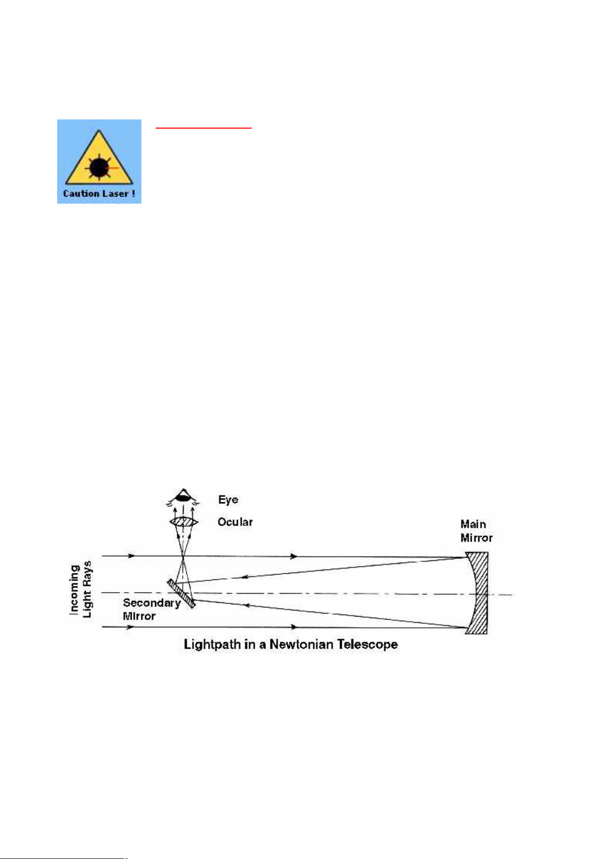
Let’s have a look again at the light path of a Newtonian telescope.
The incoming light travels first from left to right to the main mirror at the end of the tube,
is reflected there and travels right to left, to the secondary mirror, which in turn deflects
the light out of the tube and – via the eyepiece – into your eye.
Page 3
3
Loss of collimation is an important factor to be aware of with telescopes of any design if performance ‘falls off’ at any time.
A refractor’s eyepiece tilted within its eyepiece holder will show the same low quality blurred images. This holds true with all other mirror telescope systems like the popular Schmidt-Cassegrain
or Maksutov systems.
The following will guide you mainly through the collimation of a Newtonian telescope.
At the end we shall consider Schmidt-Cassegrain systems and other catadioptric instruments.
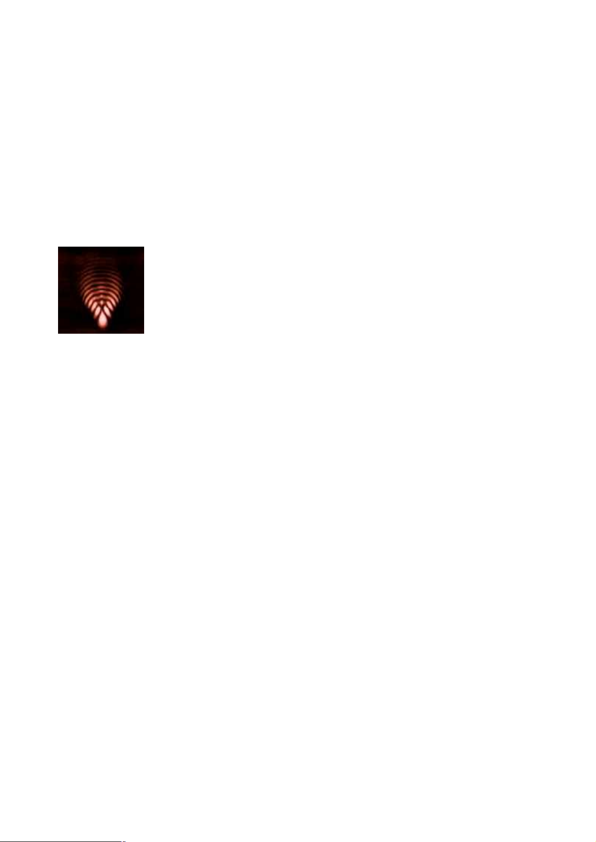
If misalignment exists in a Newtonian telescope the main image error - ‘so-called’ coma – will be
enlarged greatly and is even visible at the center of your field of view whilst normally it can be seen
only at the edges.
Please note: The larger the diameter of the main mirror and the shorter the
focal length of the optical system, the more the telescope is affected by a
small loss of collimation.
As an example: A Newtonian with a main mirror diameter of 200 mm and a
focal ratio of f/10 (2000 mm focal length) is less influenced by a slight misalignment; a Newtonian with 400 mm diameter mirror and a focal ratio of f/5
(same 2000 mm focal length) however is 4 times more affected by the same
collimation error .
Picture above shows coma error, strongly exaggerated.
Thermal turbulences blur the image to a “small comet’s trail”.
The following procedure assumes a mass marketed telescope for collimation.
Owners of homemade mirror telescopes will need to know how to collimate.
To obtain best results from collimation:
1.) The focuser (eyepiece holder) must be orientated exactly 90° vertically to the tube.
2.) The main and the secondary mirrors must be centered in the tube.
Mass marketed telescopes should fulfill both requirements. The correct center of the main mirror is
(nearly) always guaranteed by the mechanical construction of the main mirror’s cell within the tube.
The secondary mirror often can be adjusted slightly in its center position via three or four of its
vanes. With a newly bought system you can assume a correct center position. If it is not centered
this does not result in a loss of quality of the image in any case but your field of view might become
darker.
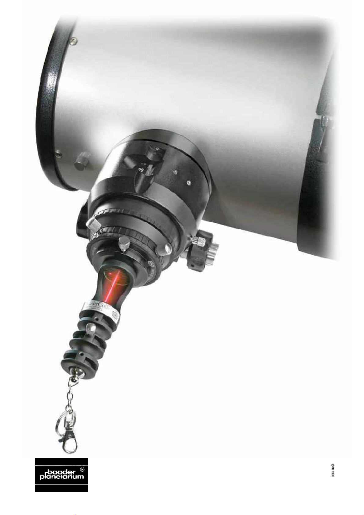
What is the function of our Laser-Colli™?
The principle is simple. The normal eyepiece (ocular) is removed and the Laser-Colli™ is slid into
the eyepiece holder and switched on. The laser beam hits the secondary mirror and is reflected
back to the main mirror, from where it is reflected again to the secondary mirror and then back into
itself through the eyepiece holder. If either or both of the mirrors are displaced from the optical axis
of the telescope system, the laser beam cannot be reflected into itself.
If the beam is reflected into itself your Newtonian system is perfectly collimated.
More often than not, this is not the case – and collimation is necessary.
Page 4
4
Of course, the LaserColli™ functions reliably
only if the laser beam itself leaves its own housing in an absolutely centered position.
Therefore the laser source
is symmetrically adjustable in the housing around
its rotational axis, which
has been carefully adjusted on a mechanical
lathe by us prior to shipping - also see following
page.
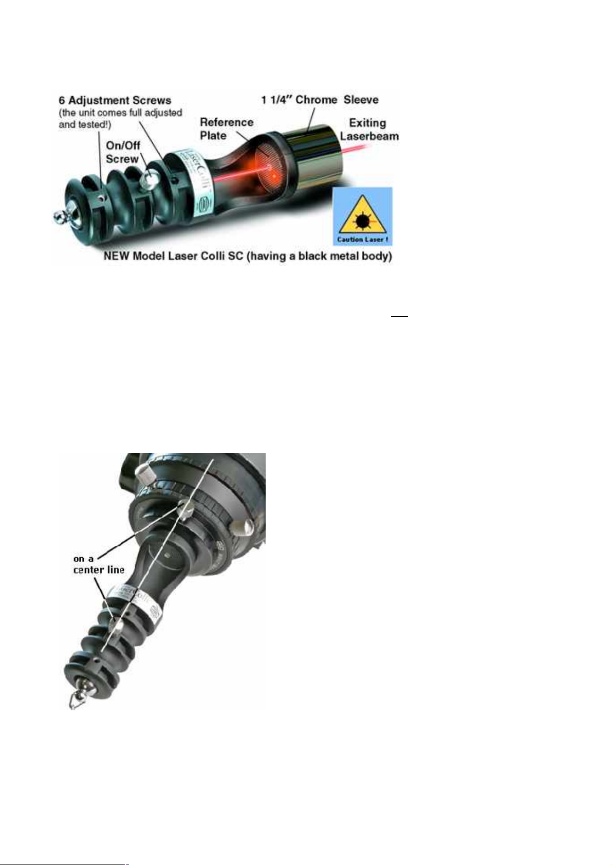
The six headless setscrews serve the purpose of adjusting the laser exactly co-axial. Please –
never try to tweak these screws yourself otherwise the laser will become tilted in its housing
and thereby misaligned. For the same reason the orientation of the Laser-Colli™ in the ocular
holder of the telescope is of utmost importance.
A few more explanations and pictures follow:
Orientation of the Laser-Colli™ in the eyepiece holder
All our Laser-Colli™ instruments are individually adjusted in an eyepiece holder on a lathe for the
required centered rotational symmetry. Necessary mechanical production tolerances for the ocular
holder and the housings of our Laser-Colli™ instruments require a correct orientation when
mounting the Laser-Colli™ into your eyepiece holder as shown below.
Please see the picture on the left:
The rear screw serving as On-Off switch for the laser
beam should be aligned with the locking screw on the
ocular holder.
If your telescope has two or more locking screws 120°
apart of each other, the rear On-Off switch screw of
the Laser-Colli™ should be orientated on a center
line just between them.
This orientation guarantees the laser alignment to be
identical to the one in your eyepiece or camera to a
fraction of a millimeter.
The Laser-Colli™ will be switched on by turning the
small thumb screw (see picture). Thereafter the laser
beam passes through the small hole in the center of
the glass reference (see picture below). The reference
has been etched with a very fine grid.
Page 5

5
On Left: Clear, translucent Reference
plane with etched cross-marks
Most laser collimating devices use a simple opaque piece of plate glass to act as
indicator for the returning laser beam.
Many small suppliers just scratch the
glass by using sand paper in order to get
a cheap opaque reference plane.
Our Clear Reference plane is etched (not
printed!) with hundreds of tiny crossmarks
so that the returning beam lights up in the
ever so tiny grooves of each individual
cross that is being touched by the laser
light.
Not only does this produce a much more
concentrated dot, the main benefit is the
fact that our reference plane is not
opaque!
Whenever your optical system is just
slightly misaligned, it is no problem to immediately recognize the reflected laser
beam on the glass reference plate.
But what happens when you don’t see any reflected dot at the reference plate due to a moderate
de-collimation of your optics?
In the case of an opaque reference plate the returned laser beam will not be visible at all and you
will be unable to view the returned beam in the focus tube.
The clear reference plane of the Laser-Colli™ will allow viewing down the focuser tube through
the etched plate, and in most cases it will be possible to glimpse a reddish glow were the laser
beam grazes the focusing tube internally.
That is the reason for placing the glass reference plate as near as possible towards the focuser
and to design the body of the Laser-Colli™ in a way that makes it easy to look almost straight into
the focus tube from behind.
Step-by-step procedure to collimate your Newtonian telescope
1. Mark the geometrical center of your primary mirror.
Remember the important requirement that the laser beam touches the primary mirror centrally –
exactly in the middle of your center mark.
If the secondary mirror is tilted only slightly out of its necessary 45° angle against the ocular holder,
the laser beam will not be reflected down towards the center of the main mirror.
Therefore you should prepare your system for the first (and all following) collimation(s) by marking
the geometrical center of the main mirror.
This requires, in Newtonian telescopes with a closed tube, removing the main mirror cell from the
tube. The removal results in the need for re-collimation afterwards of course, but this is done with
the Laser-Colli™ in no time.
Page 6

6
Read your telescope instruction manual for the correct procedure to remove the main mirror cell.
Most manuals contain this in the maintenance part ”Cleaning The Main Mirror”. Nearly all designs
hold the main mirror cell in the tube by three screws. You will find them near the rear end of the
tube spread 120° apart around the tube’s circumference. Prior to any removal mark the position
of the main mirror cell against the tube with two small sticky labels. Then carefully unscrew these
three screws and pull the main mirror cell out of the tube very cautiously.
Now make a stencil of cardboard using compasses and scissors.
The stencil’s outer diameter has to match exactly that of the main mirror.
Cut a hole of 8 to 10 millimeter diameter exactly in its geometrical center.
Place your stencil exactly above the main mirror and copy the inner edge of the small hole directly
onto the main mirror with a waterproof marker, resulting in a circle marked on the main mirror
(see next picture).
Though often mentioned in the literature, a black spot marking on the main mirror’s center is useless! You would blacken out that part of the mirror surface that is needed for the laser beam to be
returned to the Laser-Colli™.
This circle mark is hidden behind the secondary mirror and therefor has no influence whatsoever
on the imaging capability of the primary mirror.
Relocating the primary mirror:
Carefully replace the main mirror cell back into the tube to its previous position using the stickers to
locate. Replace screws etc.
The collimation procedure of a Newtonian telescope with pictures.
Step 1
Collimation always starts with a control and adjustment of the secondary mirror.
Following pictures show the view from the tube’s front end directly onto the main mirror.
Picture 1 left shows the laser beam
(red dot) obviously missing the
marker circle in the center of the main
mirrror. Note the three adjustment
Hex head screws of the secondary
mirror spread 120° apart. Very cautiously and only in small steps re-tilt
the secondary mirror by very slowly
tightening and releasing these adjustment screws.
While you look directly onto the main
mirror watch the laser’s light dot
moving into the center marker circle
while you are adjusting the secondary.
Page 7

7
Picture 2 below shows first success:
The laser’s light dot is correctly centered within the marker circle.
Most telescope constructions adjust the
secondary mirror by three loaded screws
like those (allen head screws) shown
here in the picture.
In other words: Turn one screw slowly
clockwise and the secondary mirror is
tilted in the direction towards this screw.
When the laser’s light point is centered
correctly in the marker circle, successful
adjustment of the secondary is achieved.
Step 2
Possibly the main mirror’s optical axis might be additionally tilted against that of the secondary mirror. Please observe the reference grid of the Laser-Colli™. If you see the reflected laser light
point already somewhere on the grid pane (next picture below) you are closing in on final success.
The final action is to tilt the main mirror so as to make the laser beam reflected into itself and repass through the small hole in the reference plate.
If you see this on your reference plane, adjust (tilt) your main mirror in
a way that the laser point passes exactly through the center hole thus
being reflected into itself.
Now your Newtonian optics are perfectly
collimated.
Remember to switch off the Laser Colli
whenever you don’t need it, otherwise
the batteries will be exhausted very
quickly.
Adjusting (tilting) the main mirror of a Newtonian is (nearly) always done either by three single screws or by three pairs of
screws both of which being spread 120° apart.
Details are shown in the sketch .
When there are only three single screws (upper sketch) the tilt of
the main mirror is effected by spring-loaded screw.
Once more: Turning one of the screws clockwise tilts the main
mirror towards this screw.
On most larger Newtonians, 3 pairs of push/pull screws are used (lower sketch).
Page 8

8
In the lower sketch the left side screw is threaded into the mirror support plate and will pull that
side down, the right hand screw has it’s thread cut into the bottom plate and would lift the mirror
up.
The spring loaded mirror support is easier to manufacture and to work with. On the other hand the
resilience of the springs can change with temperature and age, resulting in frequent loss of collimation of the main mirror. Therefore springs are used only in smaller Newtonian telescopes. Adjustment by push/pull screws are a little more costly to produce and more elaborate to work with
but they guarantee practically no movement of the main mirror’s adjustments due to knocks and
vibrations (transport). They are therefore mainly used in larger telescope systems with the larger
weight of the main mirror.
Adjustment of the main mirror is done best by two persons. While you are turning the main mirror’s
adjustment screws your friend would be reporting about the movement of the reflected laser light
beam.
Case 1:
The main mirror of your Newtonian may be out of adjustment quite a bit.
This may result in no success in step 1 above, i.e. you don’t see the reflected laser beam on the
reference plane at all. In this case cautiously glance through the grid towards the secondary mirror.
With a little bit of luck you will see somewhere at the inner walls of the eyepiece holder the grazing
reflection of the laser beam. If you see it, adjust the main mirror first to bring the laser beam’s light
point onto the grid – continue the adjusting operation until the beam is centered on the grid, showing full collimation.
Case 2:
You don’t see any reflection of the laser beam at all – well, your system is a long way out of adjustment.
Again your Laser-Colli™ can help.
First look into the tube front down to the primary.
On the main mirror you see the reflection of
the secondary mirror and the reference grid. In
the grid plane itself you see many reflected
images of the laser dot.
If these reflected images are not orientated in
a straight line but spread, as in the picture left,
you have to adjust the main mirror in such a
way to line them up in a straight line (see picture below).
Picture above again shows the view from the
tube’s front to the reflected images of the secondary mirror and the grid plane.
If the red reflections are exactly orientated in a
line the main mirror is well adjusted already
(white line shown in the picture serves only for
clarification).
Page 9

9
Having the reflected laser beam showing safely on the grid plane you can finish the collimation
process quickly.
Tilt the main mirror with the help of the adjustment screws until the laser beam passes through the
hole (and is reflected into itself).
That’s it! Your Newtonian is perfectly collimated. A final check of the collimation has to be done
with a star image (see below).
Picture left shows the coma error in a heavily misaligned
Newtonian – highly enlarged and exaggerated.
Picture right shows a star image also highly enlarged after
collimation (highly idealised as well).
Adjusting Schmidt-Cassegrain (SC) telescopes with the new (black body) Laser Colli
TM
Adjusting SC-Optics by means of a laser is not an easy task.
Reason being – other than in an Newtonian optical system – the SC-secondary mirror is shaped
strongly convex thereby dispersing the beam of most common lasers into a blob or otherwise oddshaped form, rendering it unusable for defining the actual center of the reflected laser beam.
It takes a careful selection of lasers (we have a reject rate of 35%) and a special technique for
sharpening the outgoing laser beam, in order to perceive a sharply defined round laser signal,
when reflected from an SC-secondary mirror.
Another, most important help in this task are the hundreds of crossmarks, etched into the reference
plate of the Laser-Colli™. They glow much more strongly compared to a simple opaque glass,
making it a lot easier to perceive the center of the reflected laser beam.
Look at the different reflections as produced by a silver colored Newton Laser-Colli™ of the first
generation, compared to the GEN II SC-Laser-Colli™ featuring a black metal body.
Page 10

10
In the silver body Laser Colli
New
(picture below) no sharp dot
is produced by the reflected
New Laser Colli,
used on Celestron
CPC SC-Optics
laser beam.
Laser Colli,
used on Celestron
114 Short Catadioptric
The alignment procedure itself is exactly the same as for a Newton optics – only much simpler.
Fasten the Laser-Colli™ straight into the SC-visual back, without using a star diagonal, in order to
avoid wrong alignment due to inaccurately tilted mirror diagonals.
Arrange the on/off contact of the Laser-Colli™ to line up with one clamp screw of the visual back,
alternatively halfway between – whenever there are two locking screws to be found.
Inspect the reflected laser beam on the reference plane – center the laser beam to fall back into
itself by tilting the secondary mirror, accessible from the front end of the optical tube.
Simplified sketch of the SC-secondary mirror
tilting mechanism. Three screws are arranged
120° apart, around a center pin on which
the secondary mirror pivots.
Loosening one screw and tightening another will tilt the mirror into the designed position.
WARNING
Loosening all three screws completely will make the secondary mirror fall off its support – possibly
falling down onto the primary mirror and creating severe damage!
Only attempt to collimate your SC-Telescope after having read fully the corresponding section in the original instruction manual .
Page 11

11
BAADER PLANETARIUM
A word of caution when collimating SC’s and other Catadioptric OTA’s:
In any Newtonian telescope it is a commonly accepted procedure, to mark the center of the primary mirror with a
small circle, before attempting collimation.
It is “The“ most important action in order to ensure control over the process of collimation (Aristotle’s: “Give me a
fixed point in space and I will unlatch the earth from it’s path“).
In terms of an SC-optical system, this would mean to mark the very center of the convex secondary (!) mirror, so as
to ensure the laser beam stays within the rotational center of the optical system.
The downside is that most visual back accessories in present day SC-OTA’s are made so sloppy that the precondition mentioned above will not be met.
Even with the best tools – a sufficiently sharp and well adjusted laser beam with a precision chrome sleeve, you must
ensure that the laser will hit the SC-secondary dead center, so that the reflected beam will truly indicate the offset of
the secondary adjustment, rather than the offset from the secondary’s center.
Putting a tiny center “ring“-mark onto a secondary is not a difficult task, when the SC-OTA has a provision to quickly
un-mount the secondary mirror – such as it is the case with CELESTRON’S FaStar-Optics.
The procedure is essentially the same, as described earlier for the center mark on a Newtonian primary.
In any case – if you do not feel happy with marking the secondary mirror of your telescope, please stick with the “real
star“ collimation techniques as described in the manual of your Schmidt-Cassegrain telescope.
We cannot take any responsibility for damaged optics sets due to careless or otherwise wrong optical handling.
Changing batteries
Your Laser ColliTM has been adjusted with the greatest of care for lifelong
service. It does not need to be removed from it’s housing for changing the
batteries. Simply turn the buckle connecting the pendant on the back of the
laser counterclockwise approximately three turns to open the battery compartment. This procedure will not alter the laser adjustment!
Replace worn-out batteries with three round “hearing aid“ batteries 1.4 Volt
(such as VARTA V675 or Panasonic PR 675 H)
Do not attempt to loosen the headless set-screws, which center the laser
within the metal body of the Laser ColliTM. Most likely you will not be able to
recover precise adjustment without extensive auxiliary equipment. The set
screws are marked with an indicator to show whenever any of the six screws
was reoriented by the user.
Please understand that precise adjustment is about the most time consuming work during the production of the Laser ColliTM. Factory realignment is expensive and involves two times freight
charges. So better not to tamper with the adjustment, it’s at it’s best already.
Note:
The diameter of the exiting laser beam almost matches the diameter of the
small hole in the reference glass.
For this reason it is possible that the beam slightly lights up on the rim of the
center hole.
This has no negative effect whatsoever on precision or functionality
of our Laser-Colli™.
Zur Sternwarte • 82291 Mammendorf • Tel.08145/8802 • Fax 08145/8805
DOK: G\engl\manuals\LaserColli-0505-e.doc
www.baader_planetarium.de • service@baader-planetarium.de • www.celestron.de
 Loading...