

Page 1

FFIIRRSSTTSSCCOOPPEE 6600 EEQQ RREEFFRRAACCTTOORRSS
MODELS #21067
FFIIRRSSTTSSCCOOPPEE 7700 EEQQ RREEFFRRAACCTTOOR
MODEL #21076
FFIIRRSSTTSSCCOOPPEE 8800 EEQQ RREEFFRRAACCTTOORRS
MODELS #21086
R
S
N
IIN
STT
S
R
R
U
U
CTTII
C
O
O
N
N
M
M
A
A
N
N
U
U
ALL
A
Page 2
FIRSTSCOPE EQ REFRACTORS
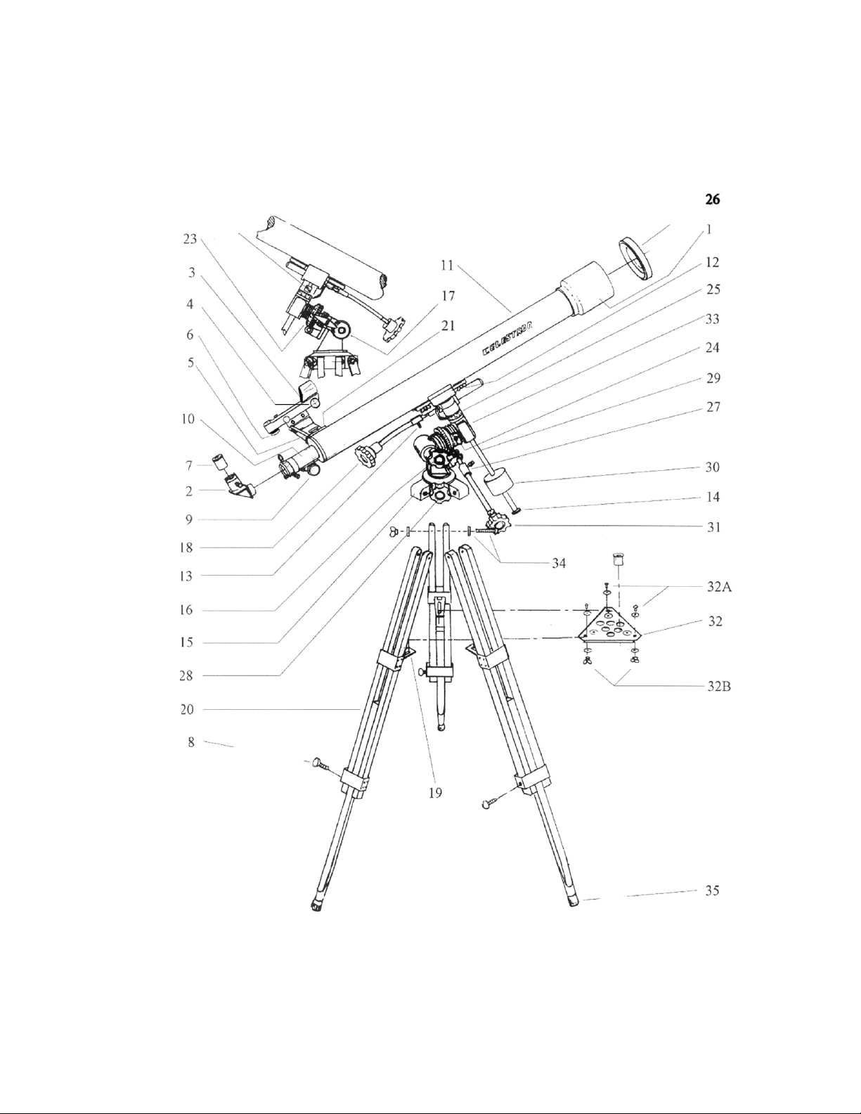
FIGURE 1
3
Page 3
LIST OF PARTS: FIRSTSCOPE EQ REFRACTORS
1. Telescope Objective (inside) 19. Tripod tray bracket (Collapsible leg
brace on some models)
2. Diagonal 20. Tripod leg
3. Star Pointer Finderscope 21. Finderscope bracket mounting screws
4. Star Pointer adjustment knob (Altitude) 22. Declination tightening knob
5. Star Pointer bracket 23. Right ascension setting circle
6. Star Pointer adjustment knob (Azimuth) 24. Right ascension tightening knob
7. Eyepiece 25. Declination setting circle
8. Tripod leg adjusting screw 26. Front lens cover
9. Focusing knob 27. Right ascension cable holder
10. Rack and pinion focuser 28. Horizontal adjustment knob
11. Telescope optical tube 29. Counterweight shaft
12. Tube mounting plate and bolts 30. Counterweight
13. Declination cable holder 31. Right ascension cable
14. Safety washer for counterweight 32. Tripod accessory tray & hardware
15. Tripod head (part of mount) 33. Equatorial mount
16. Polar axis knob 34. Tripod leg mounting hardware
17. Latitude scale 35. Tripod leg tips
18. Declination cable
4
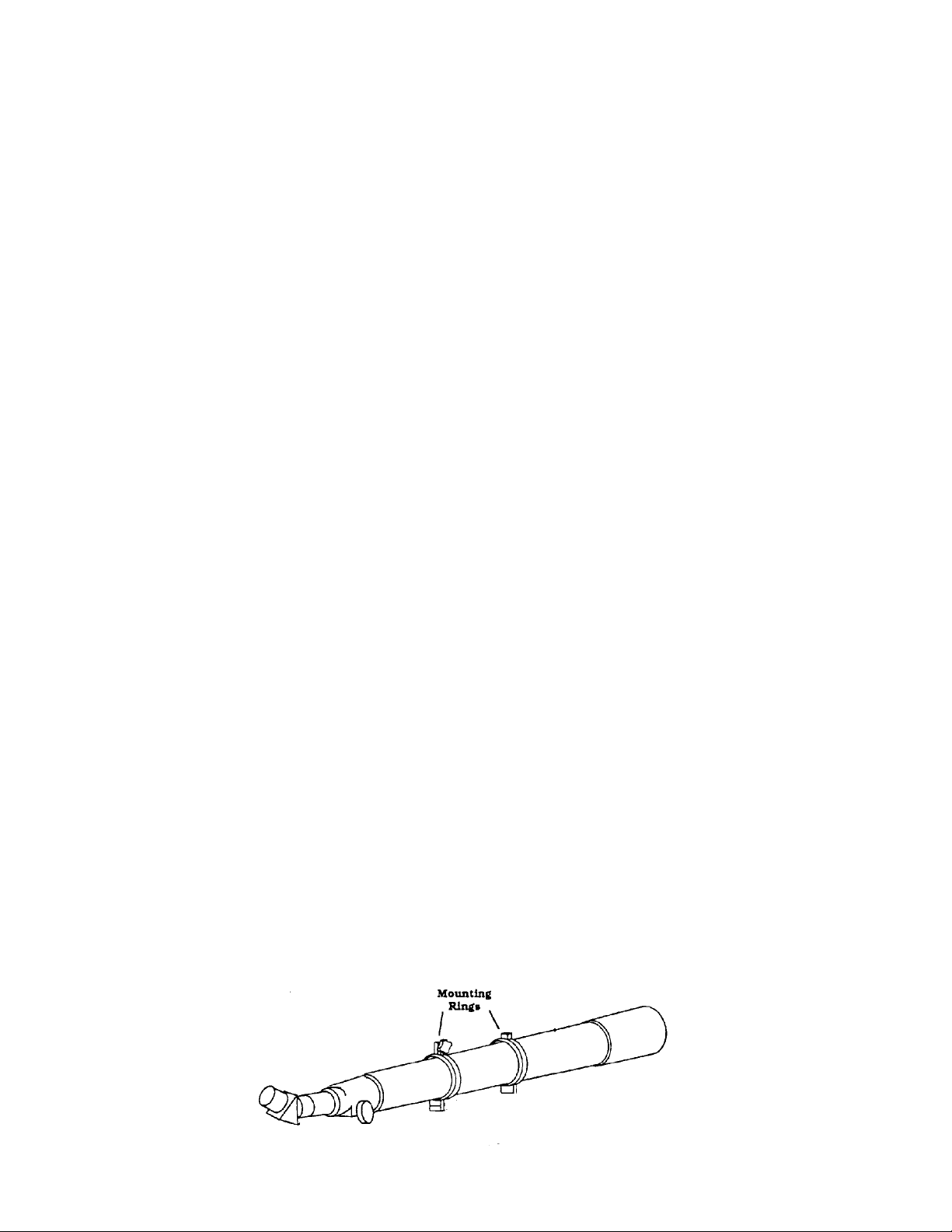
Optical Tube with Mounting Rings for 70mm/80mm Telescopes
Page 4

IINNTTRROODDUUCCTTIIOONN
Congratulations on your purchase of a Celestron equatorial refractor telescope. This telescope is a precision
scientific instrument that will allow you to enjoy viewing numerous objects in the night sky — planets, nebulae, star
clusters, galaxies and more.
Before embarking upon an exploration of the sky, please take time to read this manual and familiarize yourself with
both the parts and operation of your telescope.
WARNING
NEVER LOOK DIRECTLY AT THE SUN WITH THE NAKED EYE OR WITH A TELESCOPE. NEVER
POINT YOUR TELESCOPE AT THE SUN UNLESS YOU ARE USING THE PROPER SOLAR FILTER.
PERMANENT AND IRREVERSIBLE EYE DAMAGE MAY RESULT.
NEVER USE YOUR TELESCOPE TO PROJECT AN IMAGE OF THE SUN ONTO ANY SURFACE.
INTERNAL HEAT BUILD UP CAN DAMAGE THE TELESCOPE AND/OR ANY ACCESSORIES THAT
MAY BE ATTACHED TO IT.
NEVER LEAVE YOUR TELESCOPE UNSUPERVISED, ESPECIALLY WHEN CHILDREN ARE
PRESENT. THIS ALSO HOLDS TRUE FOR ADULTS WHO MAY NOT BE FAMILIAR WITH THE
CORRECT OPERATING PROCEDURES FOR YOUR TELESCOPE.
NEVER USE AN EYEPIECE SOLAR FILTER OR A HERSCHEL WEDGE. INTERNAL HEAT BUILD
UP WITHIN THE TELESCOPE CAN CAUSE THESE DEVICES TO CRACK, BREAK OR DAMAGE
YOUR TELESCOPE. ANY SOLAR FILTER USED SHOULD BE A FILTER FOR THE PRIMARY OR
OBJECTIVE LENS, SUCH AS CELESTRON’S ASTROSOLAR FILTER.
ALWAYS COVER THE FINDERSCOPE WHEN USING YOUR TELESCOPE WITH THE CORRECT
SOLAR FILTER. ALTHOUGH SMALL IN APERTURE, THIS INSTRUMENT HAS ENOUGH LIGHT
GATHERING POWER TO CAUSE PERMANENT AND IRREVERSIBLE EYE DAMAGE. THE IMAGE
PROJECTED BY THE FINDERSCOPE IS HOT ENOUGH TO BURN SKIN OR CLOTHING.
TTEELLEESSCCOOPPEE AASSSSEEMMBBLLY
The Firstscope comes packed in one box, with all the parts you need to assemble it. Unpack and lay out all of the
telescope parts in a large, clear area where you’ll have room to work. Use the parts list and the telescope diagram to
confirm you have, and can identify each part. The parts you’ll unpack include:
ALL TELESCOPES INCLUDE
• Telescope Optical Tube
• German Equatorial Mount
• Adjustable Tripod
• Star Pointer Finderscope and Bracket
• Counterweight and Shaft
• Tripod Accessory Tray
• Declination Cable
• Right Ascension Cable
• Star Diagonal
• The Sky® CD-ROM
• 20mm 1¼" eyepiece
• 10mm 1¼" eyepiece
Y
5
Page 5
Setting Up the Tripod
To set up the tripod, locate the German equatorial mount, the tripod legs, the tripod mounting hardware and the
tripod accessory tray.
1. Extend the center portion (35) of each of the three tripod legs down 6-8".
2. Use the three tightening screws (8) to secure each of the extended legs by threading these screws through the
holes in the brackets at the bottom of each leg. It is important that you extend the legs before the equatorial
mount is attached, otherwise the inner legs may become difficult to slide down. Fine tuning of the tripod height
can be done later, and the tightening screws can be adjusted to secure the telescope at the desired height
NOTE: Some of the following steps may have been pre-assembled at the factory for certain models.
3. Orient the three tripod legs so the brackets that hold the accessory tray are on the inside (19).
4. Slide the two top portions of each tripod leg around the sides of each flange on the tripod head (15) of the
equatorial mount, so the flange is secured between them.
5. Slide the screw through the tripod leg and flange, until the screw extends out the other side.
6. Slide the washer and the nut over the screw and tighten. This can be left slightly loose, to allow for positioning
the legs later, when attaching the accessory tray.
7. Repeat this process for the remaining two legs. Now the tripod will stand by itself.
Attaching the Accessory Tray:
1. Set the tripod with the equatorial mount attached in the standing position by spreading the legs apart far enough
for the tripod accessory tray to fit.
2. You are now ready to install the tripod accessory tray. The tripod tray fits over the holes in the tripod leg brace.
Insert the winged bolts through the holes in the bottom of the tripod leg brace and thread them into the holes in
the accessory tray. Tighten all bolts to ensure proper stability to the mount. (For the Firstscope 60 model, the
accessory tray will attach to the holes in each of the hinge brackets on the inside of each tripod leg).
SSEETTTTIINNGG UUPP TTHHEE TTEELLEESSCCOOPPE
E
Orienting the Telescope
1. Begin by identifying and loosening knobs #16, 22, 24 and 28, using the
diagram in Figure 1 to guide you.
2. Next, loosen the Right Ascension and declination knobs #24 and #22 on the
upper portion of the mount.
3. Rotate the mount head so that it is in the same orientation as shown in
Figure 1.
4. Lock down the Right Ascension and declination knobs before attaching the
optical tube.
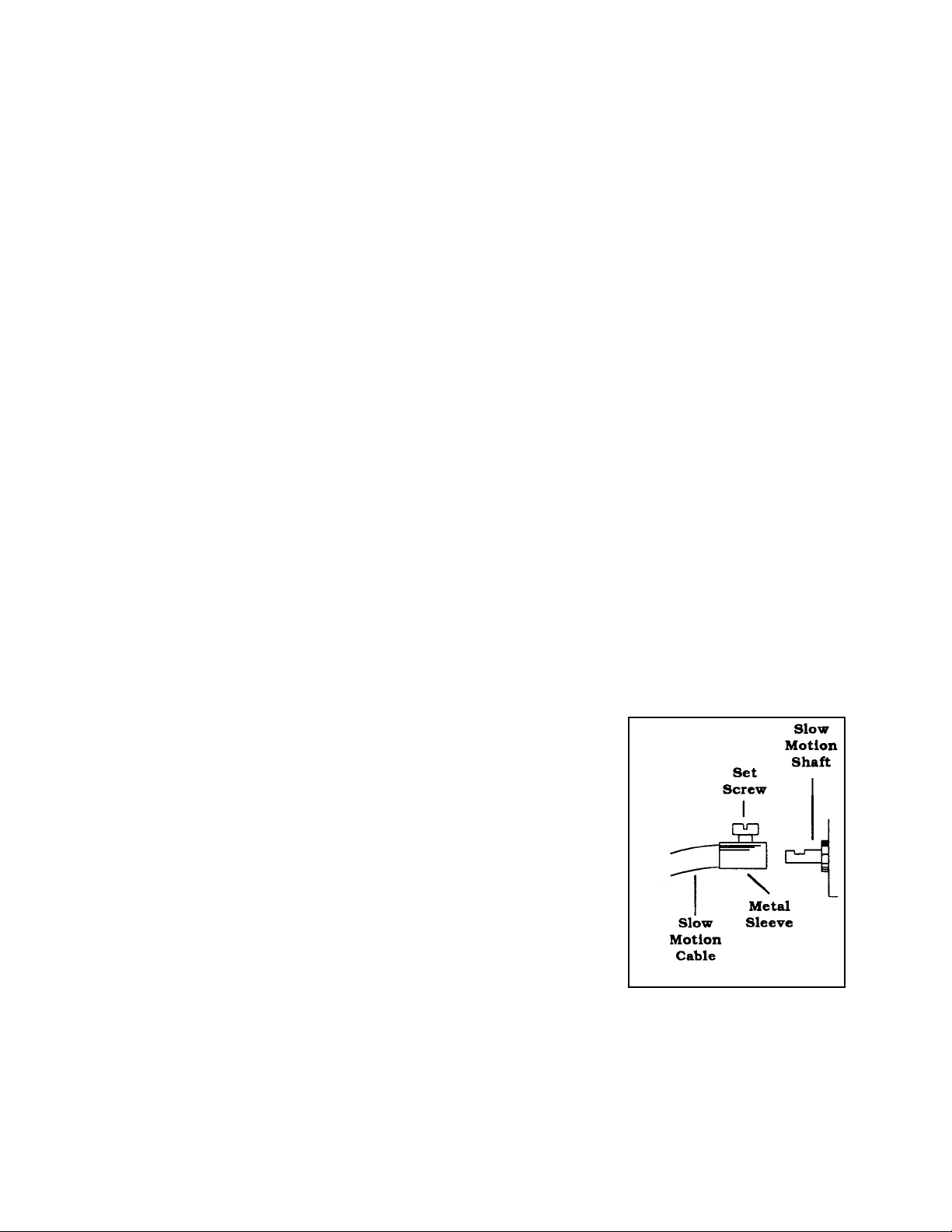
Attaching the Declination and Right Ascension Cables
1. Locate the declination cable holder (13) and the declination cable, which is
the shorter of the two cables provided.
2. Insert the declination cable (18) into the cable holder such that the cable is about ¼" short of being fully
engaged in the cable holder. Tighten the thumb screw on the end of the cable down completely. This method
helps ensure there’s no slippage when using the cable. Please note that the orientation of the declination cable
can be adjusted to the position that suits you best.
3. Locate the right ascension cable holder (27) and the right ascension cable (31) and assemble the cable to the
holder in the same manner described for the declination cable.
6
Page 6

Attaching the Counterweight
1. Thread the counterweight shaft (29) clockwise into the equatorial mount (33) as shown in Figure 1.
2. Remove the safety screw (14) from the end of the counterweight shaft
3. Slide the counterweight (30) over the counterweight shaft (29).
4. Use the screw on the side of the counterweight to secure the counterweight in place.
5. Reattach the counterweight shaft safety screw.
Installing the Telescope Optical Tube on the Equatorial Mount (60mm Models)
1. Remove the two locking nuts and two washers from the telescope optical tube (12).
2. Put the screws through the holes in the mounting plate of the equatorial mount.
3. Tighten the locking nuts on the screws.
Installing the Telescope Optical Tube on the Equatorial Mount (70mm & 80mm Models)
The optical tube is held to the mount with two mounting rings. On the bottom of the mounting rings are square
extrusions one on each ring. This portion of the ring sits on top of the mounting platform to hold the telescope in
place.
1. Slightly loosen the screws that hold the mounting rings on the telescope in place.
2. Slide the rings apart so that each is at the same distance as the holes in the mounting platform.
3. Place the telescope tube on the mount so that the flat portion of the tube rings rest on the mounting
platform.
4. Align the holes on the square extrusions with the holes at the ends of the mounting platform.
5. Starting with the ring closest to the objective lens end of the tube, insert the bolt through the hole in the
mounting platform and thread it into the mounting ring. Repeat this process for the remaining mounting
ring.
Attaching the Star Pointer Finderscope
To attach the Star Pointer Finderscope on the F60 and F70 EQ:
1. Remove the nuts from the studs where the Star Pointer will mount.
2. Mount the Star Pointer bracket by placing the bracket over the studs protruding
from the tube and tightening it down with the supplied nuts. Orient the Star Pointer
so that the glass window is facing towards the front of the tube.
To attach the Star Pointer Finderscope on the F80 EQ:
1. Slide the Star Pointer bracket into the dovetail mounting platform on top of the focuser assembly.
2. Orient the Star Pointer so that the glass window is facing towards the front of the tube.
3. Secure the Star Pointer bracket by tightening the thumb screw on the mounting platform.
7
Page 7

Installing Eyepieces
Once your telescope has been fully assembled, you are ready to attach the accessories.
The accessory adapter is the short black tube with the set screw that allows the attachment of visual accessories (i.e.,
the star diagonal, erect image diagonal, eyepieces, etc.). The accessory adapter comes attached to the focus tube and
is removed only when attaching photographic accessories.
The Star Diagonal
The star diagonal diverts the light at a right angle from the light path of the telescope. For astronomical observing,
this allows you to observe in positions that are more comfortable than if you were to look straight through. To attach
the diagonal:
1. Loosen the thumbscrew on the accessory adapter until it no longer obstructs the inner diameter.
2. Slide the chrome portion of the star diagonal into the accessory adapter of the focuser.
3. Tighten the thumbscrew on the accessory adapter to hold the diagonal in place.
If you wish to change the orientation to the diagonal, loosen the thumbscrew on the accessory adapter until the
diagonal rotates freely. Move the diagonal to the desired position and tighten the thumbscrew.
TTEELLEESSCCOOPPEE OOPPEERRAATTIIOONN —— GGEETTTTIINNGG SSEETT UUP
Setting Latitude
Loosen the polar axis knob (16) with one hand, while holding the equatorial mount with the other hand. Turn the
latitude adjustment knob located at the rear of the mount to adjust the angle of the mount. Look at the latitude scale
(17) on the side of the mount, then set the mount at the latitude of your location. For example, Los Angeles,
California is located at about 34º. If you don’t know your latitude, it can be found on a road atlas of your area.
Once the latitude is set, tighten the polar axis knob. This only has to be done once for any given latitude, and then
readjusted if the telescope is used at a different latitude.
Adjusting and Balancing Declination and Right Ascension
To move the telescope in declination (north/south) there are two options. For large and quick movements, release
the declination knob (22), move the telescope in the direction of the object you want to view, then tighten the knob
when you’re near the object. For very small movements and fine adjustments, use the declination cable (18). The
declination cable has a range of about 30°. If you get to the end of this range but haven’t yet reached the object
P
8
Page 8

you’re trying to view, you’ll want to loosen the declination lock for greater movement. Manually move the telescope
tube past the object you want to view, then use the slow motion control, in the opposite direction, to go back to the
object. Tighten the knob and reverse the direction of the declination cable. Do not try to force movement when the
declination cable has reached the end of its range. There are the same two options for moving the telescope in right
ascension (east/west). For large and quick movements, release the right ascension knob (24), move the telescope
toward the object you want to view, then tighten the knob when you’re near the object. For very small movements
and fine adjustments, use the right ascension cable (31). For quick horizontal movement, loosen the horizontal
adjustment knob.
In order for the telescope to move smoothly on both axes it must be properly balanced. To balance the right
ascension axis, move the counterweight shaft so it is parallel with the ground. Slowly release the right ascension
knob (24) and check to see if the optical tube moves. If the optical tube does move, then slide the counterweight up
or down the counterweight shaft until the optical tube remains stationary in a position parallel to the ground. When
you have achieved balance, tighten the counterweight lock nut. To balance the declination axis, follow the same
procedure, using the declination knob (22) and the tube mounting rings.
Aligning the Star Pointer Finderscope
The Star Pointer is the quickest and easiest way to point your telescope exactly at a desired object in the sky. It's like
having a laser pointer that you can shine directly onto the night sky. The Star Pointer is a zero magnification
pointing tool that uses a coated glass window to superimpose the image of a small red dot onto the night sky. While
keeping both eyes open when looking through the Star Pointer, simply move your telescope until the red dot, seen
through the Star Pointer, merges with the object as seen with your unaided eye. The red dot is produced by a lightemitting diode (LED); it is not a laser beam and will not damage the glass window or your eye. The star pointer is
powered by a long life 3-volt lithium battery (#CR2032) located underneath the front portion of the Star Pointer.
Like all finderscopes, the Star Pointer must be properly aligned with the main telescope before it can be used. This is
a simple process using the azimuth and altitude control knobs located on the side and bottom of the Star Pointer.
The alignment procedure is best done at night since the LED dot will be difficult to see during the day
.
1. To turn on the Star Pointer, rotate the variable brightness control clockwise until you here a "click". To increase
the brightness level of the red dot, continue rotating the control knob about 180º until it stops.
2. Locate a bright star or planet and center it in a low power eyepiece in the main telescope.
3. With both eyes open, look through the glass window at the alignment star.
4. If the Star Pointer is perfectly aligned, you will see the red LED dot overlap the alignment star. If the Star
Pointer is not aligned, take notice of where the red dot is relative to the bright star.
5. Without moving the main telescope, turn the Star Pointer's azimuth and altitude alignment controls until the red
dot is directly over the alignment star.
If the LED dot is brighter than the alignment star, it may make it difficult to see the star. Turn the variable brightness
control counterclockwise, until the red dot is the same brightness as the alignment star. This will make it easier to
get an accurate alignment. The Star Pointer is now ready to be used . Remember to always turn the power off
after you have found an object. This will extend the life of both the battery and the LED.
9
Page 9

UUNNDDEERRSSTTAANNDDIINNGG TTHHEE SSKKYY
The Celestial-Coordinate System
The celestial-coordinate system is an imaginary projection of the earth's geographical coordinate system onto the
celestial sphere, which gives the appearance of rotating overhead at night. This celestial grid is complete with
equator, latitudes, longitudes and poles. The celestial equator is a full 360º circle dividing the celestial sphere into
the northern celestial hemisphere and the southern celestial hemisphere. Like the earth's equator, it is the prime
parallel of latitude and is designated 0º. The celestial parallels of latitude are called “coordinates of declination
(DEC).” As with the earth's latitudes, they’re named for their angular distances from the equator. These distances
are measured in degrees, minutes and seconds of arc. There are 60 minutes of arc in each degree, and 60 seconds of
arc in each arc minute. Declinations north of the celestial equator are "+" and declinations south are "-". The north
pole is +90 and the south pole is -90 .
The celestial meridians of longitude are called “coordinates of right ascension” (RA). Like the Earth's longitude
meridians, they extend from pole to pole. There are 24 major RA coordinates, evenly spaced around the 360º
equator, one every 15º. Like the earth's longitudes, RA coordinates are a measure of time, as well as angular
distance. We speak of each of the earth's major longitude meridians as being separated by one hour of time because
the earth rotates once every 24 hours (one hour = 15°). The same principle applies to celestial longitudes since the
celestial sphere appears to rotate once every 24 hours. Right ascension hours are also divided into minutes of arc
and seconds of arc, with each hour having 60 minutes of arc and each arc minute being divided into 60 arc seconds.
Astronomers prefer the time designation for RA coordinates even though the coordinates denote locations on the
celestial sphere. Using time makes it easier to tell how long it will be before a particular star will cross a particular
north-south line in the sky. RA coordinates are marked off in units of time eastward from an arbitrary point on the
celestial equator, in the constellation Pisces. The prime RA coordinate which passes through this point is designated
“O hours O minutes O seconds.” We call this reference point the vernal equinox where it crosses the celestial
equator. All other coordinates are names for the number of hours, minutes and seconds that they lag behind the
prime coordinate after it passes overhead, moving westward.
10
Page 10

Using the celestial coordinate system, it becomes possible to find celestial objects by translating their celestial
coordinates, using telescope pointing positions. To do this, you use your RA and DEC setting circles to find celestial
coordinates for stellar objects. These coordinates are given in star charts and reference books.
Polar Alignment
To make tracking the stars easier, rough polar alignment is required.
1. The right ascension (polar) axis should be pointed towards the North Pole (see the illustration below).
2. The equatorial mount should be level.
3. Your latitude should be set (see previous section on “Setting Latitude” ).
11
Page 11

Figure 3A
For the most part, to find astronomical objects you’ll be using the right ascension axis, as polar alignment virtually
eliminates the need to adjust the declination axis. To track objects continuously, adjustments must be made with the
right ascension cable, otherwise the rotation of the earth will cause the object you’re viewing to drift out of your field
of view.
The method of polar alignment described above is adequate for casual observing. More precise methods of polar
alignment are available, and most astronomy or telescope textbooks describe these procedures.
Look at the North Star after doing the polar alignment procedure given here - your declination setting circle should
read 90º.
SSEETTTTIINNGG CCIIRRCCLLEESS
The setting circles are dials, or gauges, for right ascension and declination that allow you to locate a celestial object
easily using its coordinates, as listed in a star chart or atlas.
The declination setting circle is scaled in degrees and the right ascension setting circle is laid out in increments of
minutes. The setting circles will assist you to get close to your target, but not directly on it. It’s important to note
that the accuracy of your polar alignment will affect the accuracy of your setting circles readings.
The declination setting circle is set at the factory and won’t require adjustment if it reads accurately. The right
ascension setting circle must be aligned. Choose a bright and easy to find star on a star chart, and note its right
ascension and declination coordinates. Find the star and center it first with the Star Pointer finderscope, then in the
telescope. Rotate the right ascension circle to match the coordinates of the star with the indicator mark.
12
Page 12

The right ascension setting circle does not move as the telescope moves in right ascension, and thus it must be
aligned each time you want to use it to find a new object. However, you don’t need to use a bright star each time.
Instead, you can use the object you’re observing at the time.
Now, using a star chart or atlas, you can find numerous objects. First, move the telescope in declination to the
correct declination coordinate. Then move the telescope in right ascension until the indicator points to the correct
coordinate.
After moving the telescope to the correct celestial coordinates, look through the lower power eyepiece to see if you
have located the object you wish to view. Center the object in eyepiece. If the object is not visible in the eyepiece,
gradually pan the telescope, using the right ascension and declination cables, until the object is visible.
MMAAGGNNIIFFIICCAATTIIOONN
The magnification (or power) of a telescope varies depending upon the focal length of the eyepiece being used and
the focal length of the telescope.
The Firstscope 60 telescope has a focal length of 900mm and comes with a 20mm 1¼" eyepiece. To calculate
magnification, use the following formula, in which FL = focal length:
Therefore, if you use the 20mm eyepiece your magnification is 900/20 = 45x. The same formula can be applied to
any of your eyepieces.
Celestron offers numerous optional eyepieces to expand your range of magnification. Eyepieces come in barrel
diameters of .96" and 1¼". In general, 1¼" eyepieces are of a higher optical quality and give you sharper images,
along with a wider field of view and better eye relief.
Magnification through the telescope has its limits. These limits are determined by the laws of optics and the nature
of the human eye. The maximum usable power (with sharp images) is equal to 60 times the aperture of the telescope
(in inches). So, with a 80mm telescope it has a maximum useful power of 189x (3.15" x 60) and with the 70mm the
maximum is 165x (2.7559 x 60). Most of your viewing will be done in the range of 30x to 120x. Higher powers are
used mainly for lunar and sometimes planetary observing where you can greatly enlarge the image. The images at
extremely high powers like 675x magnify the image bur remember that the contrast will be very low and the image
somewhat blurred due to the super power. For the brightest images with the most contrast, use the lower powers
with a smaller image scale.
Magnification =
FL (telescope) in mm
FL (eyepiece) in mm
13
Page 13

TTEELLEESSCCOOPPEE OOPPEERRAATTIIOONN —— AASSTTRROONNOOMMIICCAALL OOBBSSEERRVVIINNGG
Now that your telescope is set up, you’re ready to use it for observing.
Observing the Moon
In the night sky, the moon is a prime target for your first look because it
is extremely bright and easy to find. Although the beauty of the full
moon may make it seem a perfect viewing object, in fact, the light
reflected from its fully illuminated face can be overpowering. In
addition, little or no contrast can be seen during this phase.
One of the best times to observe the moon is during its partial phases,
such as a crescent or quarter moon. At these times, long shadows reveal a
great amount of detail on the lunar surface. At low power, with the
standard eyepiece, you’ll be able to see the whole lunar disk at one time.
Change to higher power (magnification) to focus in on a smaller area.
Keep in mind that the rotation of the earth will cause the moon to drift out of your field of view. You’ll have to
manually adjust the telescope to keep the moon centered. This effect is more noticeable at higher power. Consult a
current astronomy magazine or your local newspaper to find out the current phase of the moon.
Lunar Observing Hint
To increase contrast and bring out visible detail on the lunar surface, try using different eyepiece filters (available
through your local Celestron dealer). A yellow filter works well for improving contrast.
Observing the Planets
Other easy targets include the five “naked eye” planets of our solar system, so called because they can be spotted in
the night sky by the unaided eye. You can see Venus go through its lunar-like phases. Mars can reveal a host of
surface detail and one, if not both, of its polar caps. You’ll be able to see the cloud belts of Jupiter, perhaps even
the great Red Spot. In addition, you’ll be able to see the moons of Jupiter as they orbit the giant planet. Saturn,
with its beautiful rings, is easily visible at moderate power, as is Mercury. All you need to know is where to look.
Most astronomy publications indicate where the planets are in the sky each month.
The drawing above of Jupiter provides a good representation of what you can expect to see with moderate
magnification, during good “seeing” conditions.
Observing the Sun
Although overlooked by many amateur astronomers, solar observation is both rewarding and fun. However, because
the sun is so bright, special precautions must be taken when observing this star, so as not to damage your eyes or
your telescope. Never project an image of the sun through the telescope. This can damage the telescope and/or any
14
Page 14

accessories attached to the telescope. For safe solar viewing, use a Celestron solar filter. This filter reduces the
intensity of the sun's light, making it safe to view. With this filter you can see sunspots as they move across the solar
disk and faculae, which are bright patches seen near the sun's edge. Before any solar viewing, please review the
warning in the Introduction.
To enable you to find objects you should have a set of Star Charts. The location of the planets may appear in local
newspapers.
Observing Deep-Sky Objects
Deep-sky objects are simply those objects outside the boundaries of our solar system. They include star clusters,
planetary nebulae, diffuse nebulae, double stars and other galaxies outside our own Milky Way. Unlike the sun,
moon and our five major planets, most deep-sky objects are not visible to the naked eye. Celestron Sky Maps
(#93722) can help you locate the brightest deep-sky objects.
Most deep-sky objects have a large angular size. Therefore, a low-to-moderate power eyepiece is all you need to see
them. Visually, they are too faint to reveal any of the color seen in long exposure photographs. Instead, they appear
black and white. Because of their low surface brightness, they should be observed from a “dark-sky” location. Light
pollution around large urban areas washes out most nebulae making them difficult, if not impossible, to observe.
The amount of detail you can see is dependent on your observing site (dark-sky rural locations are best), atmospheric
conditions, brightness of the object and your observing experience.
TTEELLEESSCCOOPPEE MMAAIINNTTEENNAANNCCEE
With proper care, your telescope should rarely need any maintenance work. To maintain your telescope in the best
possible condition, observe the follow suggestions:
1. When your telescope isn’t in use, replace all lens covers to keep dust and contaminants off the optical surfaces.
2. A small amount of dust on any optical surface isn’t a problem and doesn’t need to be removed. If the dust
builds up, then use a can of compressed air and a camels hair brush to remove the dust. To remove fingerprints
or other contaminants, use an optical cleaning kit or the Celestron Lens Pen (#93575).
3. If the inside of the objective lens needs cleaning, it should be done by a professional. Either have your
instrument serviced by a telescope repair facility or return it to the factory for servicing.
SSPPEECCIIFFIICCAATTIIOONNSS
Aperture 60mm 70mm 80mm
Focal Length 900mm 900mm 900mm
Focal Ratio f/15 f/13 f/11
Mounting German Equatorial German Equatorial German Equatorial
Tripod Adjustable aluminum Adjustable aluminum Adjustable aluminum
Rack & Pinion Focuser 1¼" 1¼" 1¼"
NOTE: Specifications are subject to change without notice.
Firstscope 60 Firstscope 70 Firstscope 80
15
Page 15

OOPPTTIIOONNAALL AACCCCEESSSSOORRIIEESS
Eyepieces - An assortment of eyepieces are available to give you a wide range of magnifications.
• Plössl
• Ultima - Ultima is not really a design, but a trade name for our 5-element,
Eyepiece filters - To enhance your visual observations, individual filters and
sets are available for 1¼" eyepieces.
Flashlights - Celestron’s #93592 and #93588 LED (light emitting diode) flashlights conveniently allow
you to read star maps without diminishing your night vision. Both feature adjustable brightness and are
small and lightweight, (#93592 is only 6 inches long, and weighs in at a mere 3 ounces).
Light Pollution Reduction (LPR) Filter (#94126A) - A 1¼" filter that threads into a 1¼" eyepiece,
designed to enhance your views of deep-sky astronomical objects when observed from urban areas. The
LPR filter selectively reduces the transmission of certain wavelengths of light, specifically those produced
by artificial lights. This includes mercury, and high and low pressure sodium vapor lights. Additionally, it
blocks unwanted natural light (also known as sky glow).
Motor Drive (#93515, #93510) - Motor drives compensate for the earth's rotation keeping an object in the eyepiece
field of view. This makes observing much more enjoyable and eliminates the constant use of the manual cables.
Models available for all equatorial mounts.
Sky Maps (#93722) - When learning the night sky, Celestron Sky Maps offer just the guidance you need.
The maps show all the constellations and brighter deep-sky objects and are printed on heavy, moistureresistant paper for durability. The front cover features a rotating planisphere, indicating when specific
constellations are visible.
Solar Filters - Celestron’s AstroSolar solar filters permit completely safe, direct observation of the sun.
This filter, which transmits .001% of visible light, allows sunspots to be seen as they move across the solar
disk. While reducing the intensity of the sun's visible light, it also blocks 99.999% of invisible infrared
light. The solar filter is made of precision engineered Mylar polyester film. A layer of aluminum is
vacuum-deposited on one surface of the dual sheets of Mylar used to make each filter. This aluminum
coating produces a cool, comfortable, pale blue image of the sun. A #21 orange eyepiece filter works well
in conjunction with the AstroSolar filter to produce a more naturally colored image of the sun.
Peterson First Guides® - Astronomy
A simplified field guide to the stars, the planets and the universe featuring full color maps showing the positions of
the stars throughout the year. This useful guide also includes beautiful constellation paintings, photographs, and
clear, concise descriptions of stars, the planets, the sun, the moon, comets, black holes, galaxies and more.
Planisphere (#93720) - A colorful rotating star map that indicates when specific constellations are visible,
with removable markers for tracking the movement of planets. Available in three different latitudes: 30°, 40°,
and 50° all ±10°.
A full description of all Celestron accessories can be found in the Celestron Accessory Catalog (#93685).
- Plössl eyepieces have a 4-element lens designed for low-to-high
power observing. The Plössls offer razor sharp views across the entire
field, even at the edges! In the 1-1/4" barrel diameter, they are available in
the following focal lengths: 6.3mm, 7.5mm, 10mm, 12.5mm, 17mm,
20mm, 26mm, 32mm and 40mm.
wide field eyepieces. In the 1-1/4" barrel diameter, they are available in
the following focal lengths: 5mm, 7.5mm, 12.5mm, 18mm, 24mm, 30mm,
35mm, and 42mm. These eyepieces are all parfocal. The 35mm Ultima
gives the widest possible field of view with a 1-1/4" diagonal.
16
Page 16

CELESTRON TWO YEAR WARRANTY
A. Celestron warrants this telescope to be free from defects in materials and workmanship for two years. Celestron will repair or replace such product or part
thereof which, upon inspection by Celestron, is found to be defective in materials or workmanship. As a condition to the obligation of Celestron to repair or
replace such product, the product must be returned to Celestron together with proof-of-purchase satisfactory to Celestron.
B. The Proper Return Authorization Number must be obtained from Celestron in advance of return. Call Celestron at (310) 328-9560 to receive the number to be
displayed on the outside of your shipping container.
All returns must be accompanied by a written statement setting forth the name, address, and daytime telephone number of the owner, together with a brief
description of any claimed defects. Parts or product for which replacement is made shall become the property of Celestron.
The customer shall be responsible for all costs of transportation and insurance, both to and from the factory of Celestron, and shall be required to
prepay such costs.
Celestron shall use reasonable efforts to repair or replace any telescope covered by this warranty within thirty days of receipt. In the event repair or replacement
shall require more than thirty days, Celestron shall notify the customer accordingly. Celestron reserves the right to replace any product which has been
discontinued from its product line with a new product of comparable value and function.
This warranty shall be void and of no force of effect in the event a covered product has been modified in design or function, or subjected to abuse,
misuse, mishandling or unauthorized repair. Further, product malfunction or deterioration due to normal wear is not covered by this warranty.
CELESTRON DISCLAIMS ANY WARRANTIES, EXPRESS OR IMPLIED, WHETHER OF MERCHANTABILITY OF FITNESS FOR A PARTICULAR
USE, EXCEPT AS EXPRESSLY SET FORTH HEREIN.
THE SOLE OBLIGATION OF CELESTRON UNDER THIS LIMITED WARRANTY SHALL BE TO REPAIR OR REPLACE THE COVERED PRODUCT, IN
ACCORDANCE WITH THE TERMS SET FORTH HEREIN. CELESTRON EXPRESSLY DISCLAIMS ANY LOST PROFITS, GENERAL, SPECIAL,
INDIRECT OR CONSEQUENTIAL DAMAGES WHICH MAY RESULT FROM BREACH OF ANY WARRANTY, OR ARISING OUT OF THE USE OR
INABILITY TO USE ANY CELESTRON PRODUCT. ANY WARRANTIES WHICH ARE IMPLIED AND WHICH CANNOT BE DISCLAIMED SHALL BE
LIMITED IN DURATION TO A TERM OF TWO YEARS FROM THE DATE OF ORIGINAL RETAIL PURCHASE.
Some states do not allow the exclusion or limitation of incidental or consequential damages or limitation on how long an implied warranty lasts, so the above
limitations and exclusions may not apply to you.
This warranty gives you specific legal rights, and you may also have other rights which vary from state to state.
Celestron reserves the right to modify or discontinue, without prior notice to you, any model or style telescope.
If warranty problems arise, or if you need assistance in using your telescope contact:
Celestron
Customer Service Department
2835 Columbia Street
Torrance, CA 90503
Tel. (310) 328-9560
Fax. (310) 212-5835
Monday-Friday 8AM-4PM PST
This warranty supersedes all other product warranties.
NOTE: This warranty is valid to U.S.A. and Canadian customers who have purchased this product from an Authorized Celestron Dealer in the U.S.A. or
Canada. Warranty outside the U.S.A. and Canada is valid only to customers who purchased from a Celestron Distributor or Authorized Celestron Dealer
in the specific country and please contact them for any warranty service
Printed in China 05-03
 Loading...