

Page 1
ENGLISH
PPoow
weerrSSeeeekkeerr
®
®
SSeerriieess TTeelleessccooppeess
IINNSSTTRRUUCCTTIIOONN MMAANNUUAALL
●● PPoowweerrSSeeeekkeerr 6600EEQQ ## 2211004433 ●● PPoowweerrSSeeeekkeerr 7700EEQQ ## 2211003377
●● PPoowweerrSSeeeekkeerr 8800EEQQ ## 2211004488 ●● PPoowweerrSSeeeekkeerr 111144EEQQ ## 2211004455
●● PPoowweerrSSeeeekkeerr 112277EEQQ ## 2211004499
Page 2

Table of Contents
INTRODUCTION ..........................................................................................................................3
ASSEMBLY ................................................................................................................................... 6
Setting up the Tripod............................................................................................................................................. 6
Attaching the Equatorial Mount .......................................................................................................................... 7
Installing the Counterweight Bar & Counterweight(s) ...................................................................................... 7
Attaching the Slow Motion Cables....................................................................................................................... 8
Attaching the Telescope Tube to the Mount........................................................................................................ 8
Installing the Diagonal & Eyepiece (Refractor).................................................................................................. 9
Installing the Eyepiece on the Newtonian............................................................................................................ 9
Installing the Finderscope................................................................................................................................... 10
Aligning the Finderscope..................................................................................................................................... 10
Installing and Using the Barlow Lens ................................................................................................................ 10
Moving the Telescope Manually......................................................................................................................... 11
Balancing the Mount in R.A. .............................................................................................................................. 11
Balancing the Mount in Dec................................................................................................................................ 11
Adjusting the Equatorial Mount ........................................................................................................................ 12
Adjusting the Mount in Altitude......................................................................................................................... 12
TELESCOPE BASICS .................................................................................................................13
Image Orientation................................................................................................................................................ 14
Focusing................................................................................................................................................................ 14
Calculating Magnification................................................................................................................................... 14
Determining Field of View .................................................................................................................................. 15
General Observing Hints..................................................................................................................................... 15
ASTRONOMY BASICS .............................................................................................................. 16
The Celestial Coordinate System........................................................................................................................ 16
Motion of the Stars .............................................................................................................................................. 16
Polar Alignment with the Latitude Scale........................................................................................................... 17
Pointing at Polaris................................................................................................................................................ 18
Finding the North Celestial Pole......................................................................................................................... 18
Polar Alignment in the Southern Hemisphere .................................................................................................. 19
Aligning the Setting Circles................................................................................................................................. 21
Motor Drive.......................................................................................................................................................... 22
CELESTIAL OBSERVING .........................................................................................................23
Observing the Moon ............................................................................................................................................ 23
Observing the Planets.......................................................................................................................................... 23
Observing the Sun................................................................................................................................................ 23
Observing Deep-Sky Objects .............................................................................................................................. 24
Seeing Conditions................................................................................................................................................. 24
ASTROPHOTOGRAPHY............................................................................................................ 25
Short Exposure Prime Focus Photography ....................................................................................................... 25
Piggyback Photography....................................................................................................................................... 25
Planetary & Lunar Photography with Special Imagers................................................................................... 25
CCD Imaging for Deep Sky Objects .................................................................................................................. 25
Terrestrial Photography...................................................................................................................................... 25
TELESCOPE MAINTENANCE.................................................................................................. 26
Care and Cleaning of the Optics......................................................................................................................... 26
Collimation of a Newtonian................................................................................................................................. 26
OPTIONAL ACCESSORIES ..................................................................................................... 29
POWERSEEKER SPECIFICATIONS......................................................................................... 30
2
Page 3

Congratulations on your purchase of a PowerSeeker telescope. The PowerSeeker Series of telescopes come in
several different models and this manual covers five models mounted on a German Equatorial Mount --- 60mm
refractor, 70mm refractor, 80mm refractor, 114mm Newtonian, and 127mm Newtonian. The PowerSeeker Series is
made of the highest quality materials to ensure stability and durability. All this adds up to a telescope that gives you
a lifetime of pleasure with a minimal amount of maintenance.
These telescopes were designed for the First Time Buyer offering exceptional value. The PowerSeeker series
features a compact and portable design with ample optical performance to excite any newcomer to the world of
amateur astronomy.
PowerSeeker telescopes carry a two year limited warranty. For details see our website at www.celestron.com
Some of the many standard features of the PowerSeeker include:
• All coated glass optical elements for clear, crisp images.
• Smooth functioning, rigid equatorial mount with setting circles in both axes.
• Preassembled aluminum tripod ensures a stable platform.
• Quick and easy no-tool set up.
• CD-ROM “The Sky” Level 1 -- astronomy software which provides education about the sky and printable sky
maps.
• All models can be used terrestrially as well as astronomically with the standard accessories included.
Take time to read through this manual before embarking on your journey through the Universe. It may take a few
observing sessions to become familiar with your telescope, so you should keep this manual handy until you have
fully mastered your telescope’s operation. The manual gives detailed information regarding each step as well as
needed reference material and helpful hint to make your observing experience as simple and pleasurable as possible.
Your telescope is designed to give you years of fun and rewarding observations. However, there are a few things to
consider before using your telescope that will ensure your safety and protect your equipment.
Warning
y Never look directly at the sun with the naked eye or with a telescope (unless you have the proper
solar filter). Permanent and irreversible eye damage may result.
y Never use your telescope to project an image of the sun onto any surface. Internal heat build-up can
damage the telescope and any accessories attached to it.
y Never use an eyepiece solar filter or a Herschel wedge. Internal heat build-up inside the telescope can
cause these devices to crack or break, allowing unfiltered sunlight to pass through to the eye.
y Do not leave the telescope unsupervised, either when children are present or adults who may not be
familiar with the correct operating procedures of your telescope.
3
Page 4
8
12
13
16
1
4
5
2
15
3
8
14
7
6
9
11
10
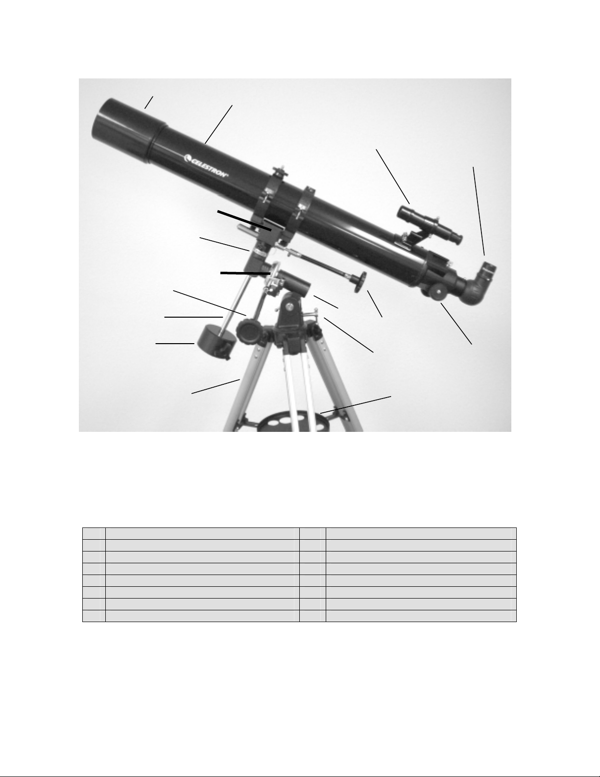
Figure 1-1 PowerSeeker 80EQ Refractor
PowerSeeker 60EQ & PowerSeeker 70EQ Similar
1. Telescope Optical Tube 9. Latitude Adjustment Screw
2. Mounting Bracket w/ Tube Rings 10. Tripod Accessory Tray
3. R.A. Setting Circle 11. Tripod
4. Finderscope 12. Counterweight Bar
5. Eyepiece & Diagonal 13. Counterweight
6. Focus Knob 14. Equatorial Mount
7. Dec. Slow Motion Cable 15. Dec. Setting Circle
8. R.A. Slow Motion Cable 16. Objective Lens
4
Page 5
1
14
2
13
12
10
6
7
9
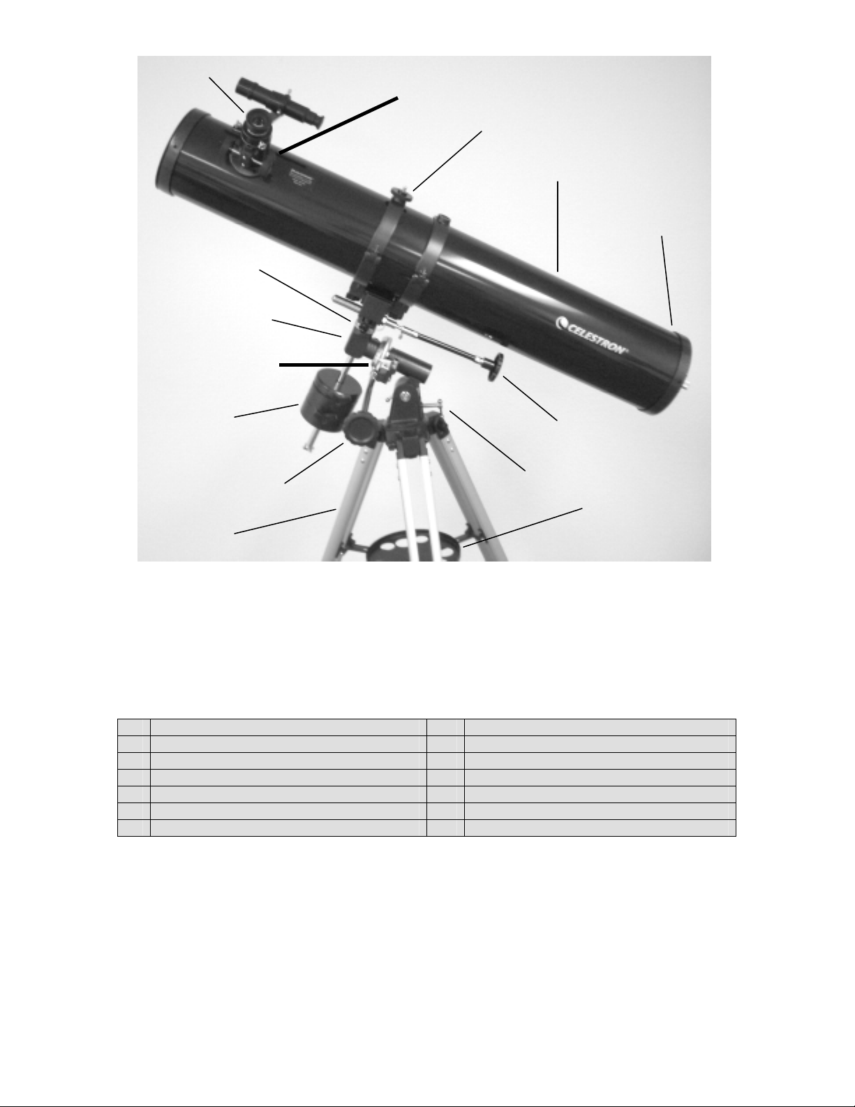
Figure 1-2 PowerSeeker 114EQ Newtonian
PowerSeeker 127EQ Newtonian Similar
1. Eyepiece 8. Tripod Accessory Tray
2. Tube Ring 9. Tripod
3. Telescope Optical Tube 10. Counterweight
4. Primary Mirror 11. R.A. Setting Circle
5. Dec. Slow Motion Cable 12. Equatorial Mount
6. R.A. Slow Motion Cable 13. Dec. Setting Circle
7. Latitude Adjustment Screw 14. Focus Knob
3
4
5
8
5
Page 6
This section covers the assembly instructions for your PowerSeeker telescope. Your telescope should be set up
indoor the first time so that it is easy to identify the various parts and familiarize yourself with the correct assembly
procedure before attempting it outdoor.
Each PowerSeeker comes in one box. The pieces in the box are – optical tube, tube rings (except 60EQ), German
equatorial mount, counterweight bar, counterweight, R.A. & Dec. slow-motion cables, 4mm eyepiece – 1.25”,
20mm eyepiece – 1.25” (erect image for 114EQ & 127EQ), erect image diagonal 1.25” (for 60EQ, 70EQ, and
80EQ), 3x Barlow Lens 1.25”, “The Sky” Level 1 CD-ROM.
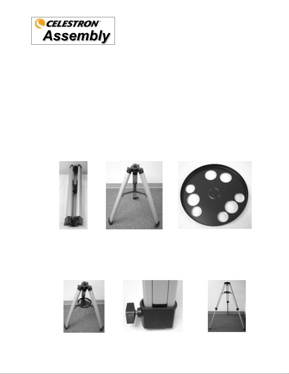
SSeettttiinngg uupp tthhee TTrriippoodd
1. Remove the tripod from the box (Figure 2-1). The tripod comes preassembled so that the set up is very
easy.
2. Stand the tripod upright and pull the tripod legs apart until each leg is fully extended and then push down
slightly on the tripod leg brace (Figure 2-2). The very top of the tripod is called the tripod head.
3. Next, we will install the tripod accessory tray (Figure 2-3) onto the tripod leg brace (center of Figure 2-2).
4. On the bottom of the tripod tray is a screw attached to the center. The screw attaches into a threaded hole
in the center of the tripod leg brace by turning it counterclockwise - note: pull up slightly on the tripod leg
brace to make it easy to attach. Continue turning the tray until hand tight – don’t over tighten the tray.
5. The tripod is now completely assembled (Figure 2-4).
6. You can extend the tripod legs to the height you desire. At the lowest level the height is 26” (66cm) and
7. The tripod will be the most rigid and stable at the lower heights.
Figure 2-1 Figure 2-2 Figure 2-3
extends to 47” (119cm). You unlock the tripod leg lock knob at the bottom of each leg (Figure 2-5) by
turning them counterclockwise and pull the legs out to the height you want & then lock the knob securely.
A fully extended the tripod looks like the image in Figure 2-6.
Figure 2-4 Figure 2-5 Figure 2- 6
6
Page 7
t
AAttttaacchhiinngg tthhee EEqquuaattoorriiaall MMoouunnt
The equatorial mount allows you to tilt the telescopes axis of rotation so that you can track the stars as they move
across the sky. The PowerSeeker mount is a German equatorial mount that attaches to the tripod head. To attach
the mount:
1. Remove the equatorial mount from the box (Figure 2-8). The mount has the latitude locking bolt attached to
it (Figure 2-27). The latitude adjustment screw attaches to the threaded hole in the mount as shown in Figure
2-10.
2. The mount will attach to the tripod head and more specifically to the knob with bolt attached under the tripod
head (Figure 2-7). Push the mount (large flat portion with a small tube sticking out) into the center hole of the
tripod head until it is flush and hold it steady. Then, reach under the tripod head with your other hand and
turn the knob counterclockwise which will thread it into the bottom of the mount. Continue turning until it is
tight. The completed assembly of the mount to the tripod is seen in Figure 2-9.
Figure 2-7 Figure 2-8 Figure 2-9 Figure 2-10
IInnssttaalllliinngg tthhee CCoouunntteerrwweeiigghhtt BBaarr && CCoouunntteerrwweeiigghhtt((ss))
To properly balance the telescope, the mount comes with a counterweight bar and one or two counterweights
(depending on the model you have). To install them:
1. Remove the counterweight safety screw from the counterweight bar (at the opposite end of the threaded rod)
by unthreading it counterclockwise – see Figure 2-11.
2. Install the large threads of the counterweight bar into the threaded hole in the Dec. axis of the mount and turn
clockwise-- see Figure 2-12 until it is tight. Now you are ready to attach the counterweight(s).
3. Orient the mount so that the counterweight bar points toward the ground.
4. Loosen the locking knob on the side of the counterweight so that the threads do not protrude through the
center hole of the counterweight.
5. Slide the counterweight onto the counterweight bar about half way up and tighten the locking knob securely.
The correct orientation of the weight is shown in Figure 2-13.
6. Slide the second counterweight (if your model has a second weight) onto the counterweight bar flush up
against the first one and then lock securely.
7. Replace the safety screw and thread it on securely. The completed assembly is shown in Figure 2-13.
Figure 2-11 Figure 2-12 Figure 2-13
7
Page 8
AAttttaacchhiinngg tthhee SSllooww MMoottiioonn CCaabblleess
The PowerSeeker mount comes with two slow motion control cables that allow you to make fine pointing
adjustments to the telescope in both R.A. and Declination. To install the cables:
1. Locate the two cables with knobs on them. The longer one is for the R.A. axis and make sure the screw on
each cable end does not protrude through the opening.
2. Slide the cable onto the R.A. shaft (see Figure 2-14) so the screw fits over the groove in the R.A. Shaft.
There are two R.A. shafts, one on either side of the mount. It makes no difference which shaft you use since
both work the same (except if using a motor drive). Use whichever one you find more convenient.
3. Tighten the screw on the R.A. cable to hold it securely in place.
4. The DEC slow motion cable attaches in the same manner as the R.A. cable. The shaft that the DEC slow
motion knob fits over is toward the top of the mount, just below the telescope mounting platform.
Figure 2-14
R.A. Shaft on bottom below the R.A. Setting
Circle Dec. Shaft on top above the Dec. Setting
Circle
AAttttaacchhiinngg tthhee TTeelleessccooppee TTuubbee ttoo tthhee MMoouunntt
R.A. & Dec. Cables attached
Figure 2-15
The telescope optical tube attaches to the equatorial mount with tube rings (except on the 60EQ) supporting it to the
mounting bracket at the top of the mount (Figure 2-16). For the 60EQ refractor, the tube mounts directly to the
mounting bracket with the screw studs attached to the optical tube. Before you attach the optical tube, make sure
that the declination and right ascension locking knobs are tight (Figure 2-24). Then, make sure that the
latitude adjustment screw and latitude locking bolt (Figure 2-27) are tight. This will ensure that the mount does
not move suddenly while attaching the telescope optical tube. Also, remove the objective lens cap (refractor) or the
front opening cap (Newtonian). To mount the telescope tube:
1. Remove the protective paper covering the optical tube. You will have to remove the tube rings (Figure 2-16)
before removing the paper.
2. Remove the knobs from the threaded posts at the bottom of the tube rings (Figure 2-16).
3. Now put the posts through the holes in the top of the mount platform (Figure 2-17) and put the knobs back on
and tighten and they will look like Figure 2-18.
4. Open the tube rings (loosen the large chromed knobs) so that the optical tube can be put on.
5. Hold the optical tube carefully with one hand and center in the tube rings and close the rings and latch and
tighten the knurled knobs of the tube rings which will look like Figure 2-19.
6. Note that you could attach the tube rings to the optical tube first and then attach to the mounting platform on
the equatorial mount as this is a personal preference.
NOTE: Never loosen any of the knobs on the telescope tube or mount other than the R.A. and DEC knobs.
Hint: For maximum rigidity of the telescope and mount, make sure the knobs/screws holding the tripod legs to the
tripod head are tight.
8
Page 9
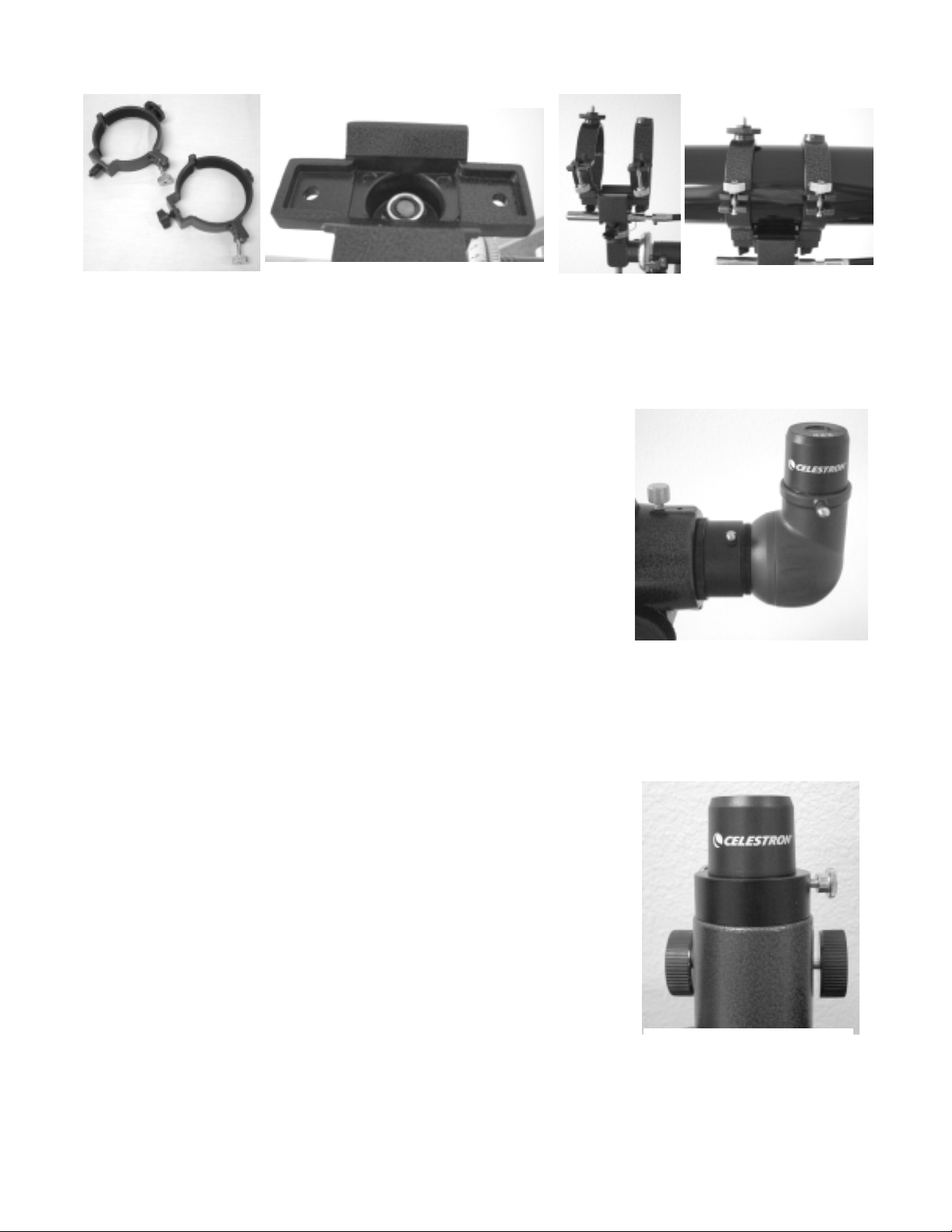
Figure 2-16 Figure 2-17 Figure 2-18 Figure 2-19
IInnssttaalllliinngg tthhee DDiiaaggoonnaall && EEyyeeppiieeccee ((RReeffrraaccttoorr))
The diagonal is a prism that diverts the light at a right angle to the light path of
the refractor. This allows you to observe in a position that is more comfortable
than if you had to look straight through. This diagonal is an erect image model
that corrects the image to be right side up and oriented correctly left-to-right
which is much easier to use for terrestrial observing. Also, the diagonal can be
rotated to any position which is most favorable for you. To install the diagonal
and eyepieces:
1. Insert the small barrel of the diagonal into the 1.25” eyepiece adapter of the
focus tube on the refractor – Figure 2-20. Make sure the two thumbscrews
on the eyepiece adapter do not protrude into the focuser tube before
installation and the plug up cap is removed from the eyepiece adapter.
2. Put the chrome barrel end of one of the eyepieces into the diagonal and
tighten the thumb screw. Again, when doing this make sure the thumb
screw is not protruding into the diagonal before inserting the eyepiece.
3. The eyepieces can be changed to other focal lengths by reversing the
Figure 2-20
procedure in step 2 above.
IInnssttaalllliinngg tthhee EEyyeeppiieeccee oonn tthhee NNeewwttoonniiaann
The eyepiece (or ocular) is an optical element that magnifies the image focused by
the telescope. Without the eyepiece it would be impossible to use the telescope
visually. Eyepieces are commonly referred to by focal length and barrel diameter.
The longer focal length (i.e., the larger the number) the lower the eyepiece
magnification (i.e., power). Generally, you will use low-to-moderate power when
viewing. For more information on how to determine power, see the section on
“Calculating Magnification”. The eyepiece fits directly into the focuser of the
Newtonian. To attach the eyepieces:
1. Make sure the thumbscrews are not protruding into the focuser tube. Then,
insert the chrome barrel of the eyepieces into the focus tube (remove the
plug up cap of the focuser first) and tighten the thumbscrews – see
Figure 2-21.
2. The 20mm eyepiece is called an erecting eyepiece since it corrects the
image so it is right side up and corrected left to right. This makes the
telescope useful for terrestrial viewing.
Figure 2-21
3. The eyepieces can be changed by reversing the procedure as described
above.
9
Page 10
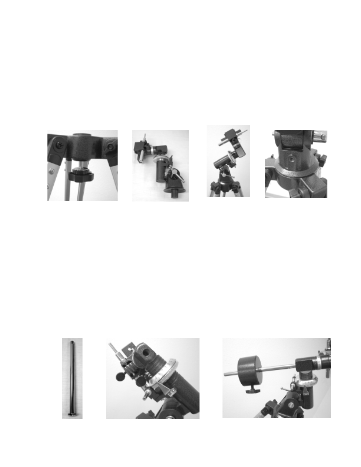
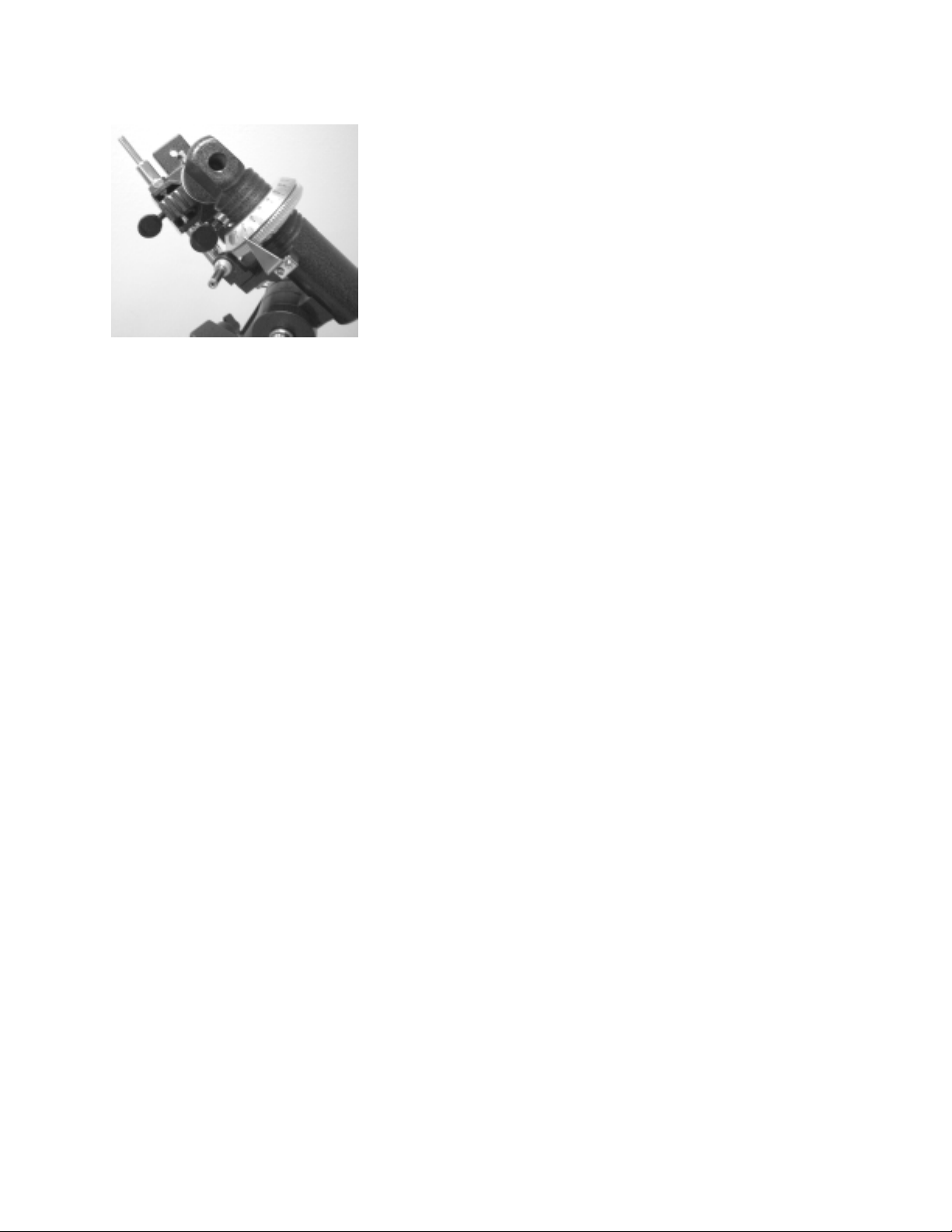
IInnssttaalllliinngg tthhee FFiinnddeerrssccooppee
To install the finderscope:
1. Locate the finderscope (it will be mounted inside the finderscope
bracket) – see Figures 1-1 and 1-2.
2. Remove the knurled nuts on the threaded posts on the optical tube –
see Figure 2-22.
3. Mount the finderscope bracket by placing it over the posts protruding
from the optical tube and then holding it in place thread on the
knurled nuts and tighten them down – note that the finderscope
should be oriented so that the larger diameter lens is facing toward
the front of the optical tube.
4. Remove the lens caps from both ends of the finderscope.
AAlliiggnniinngg tthhee FFiinnddeerrssccooppee
Use the following steps to align the finderscope:
1. Locate a distant daytime object and center it in a low power (20mm) eyepiece in the main telescope.
2. Look through the finderscope (the eyepiece end of the finderscope) and take notice of the position of the
same object.
3. Without moving the main telescope, turn the adjustment thumb screws located around the finderscope
bracket until the crosshairs of the finderscope are centered on the object chosen with the main telescope.
Figure 2-22
Objective Lens
Finderscope Bracket
Figure 2-22a Finderscope with Bracket
10
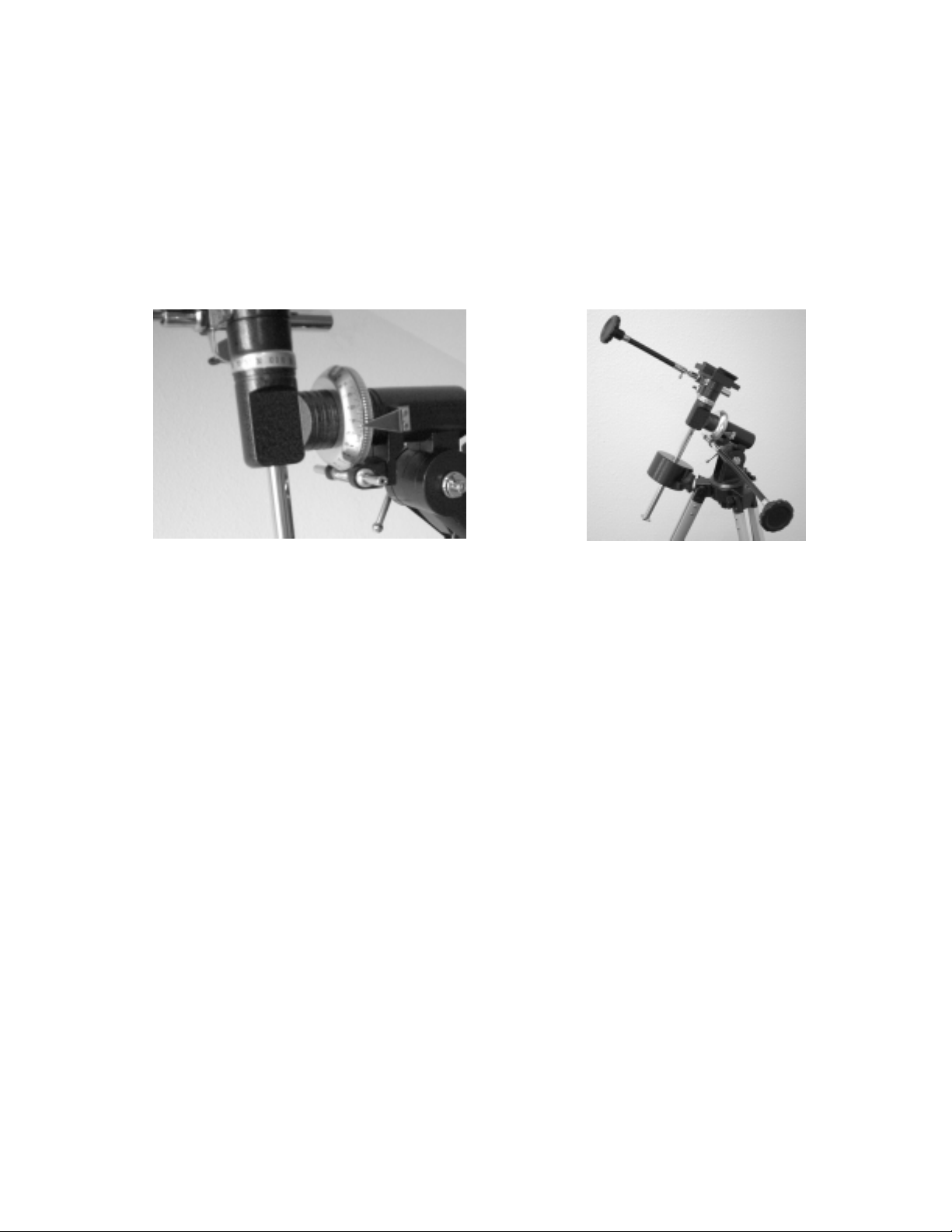
IInnssttaalllliinngg aanndd UUssiinngg tthhee BBaarrllooww LLeennss
Your telescope also comes with a 3x Barlow Lens which triples the
magnifying power of each eyepiece. However, the greatly magnified
images should only be used under ideal conditions – see the “Calculating
Magnification” section of this manual.
To use the Barlow lens with refractors, remove the diagonal and insert the Barlow directly into the focuser tube.
You then insert an eyepiece into the Barlow lens for viewing. You can also, insert the diagonal into the Barlow lens
and then use an eyepiece in the diagonal but you may not be able to reach focus with all eyepieces.
For Newtonian telescopes, insert the Barlow directly into the focuser. Then, insert an eyepiece into the Barlow lens.
Note: Start by using a low power eyepiece as it will be easier to focus.
Figure 2-23
3x Barlow Lens Magnification
60EQ 70EQ 80EQ 114EQ 127EQ
w/20mm Eyepiece 135x 105x 135x 135x 150x
w/4mm Eyepiece 675x 525x 675x 675x 450x
Eyepiece
Adjustment Screws
Page 11
MMoovviinngg tthhee TTeelleessccooppee MMaannuuaallllyy
In order to properly use your telescope, you will need to move your
telescope manually at various portions of the sky to observe different
objects. To make rough adjustments, loosen the R.A. and Dec. locking
knobs slightly and move the telescope in the desired direction. To make
fine adjustments, when the knobs are locked you turn the slow motion
control cables.
Both the R.A. and Dec. axis have locking knobs to clutch down each axis
of the telescope. To loosen the clutches on the telescope, unlock the
locking knobs.
Figure 2-24
Dec. Lock Knob on top of Dec.circle
& R.A. Lock Knob on top of R.A.
circle
BBaallaanncciinngg tthhee MMoouunntt iinn RR..AA..
To eliminate undue stress on the mount, the telescope should be properly balanced around the polar axis. In
addition, proper balancing is crucial for accurate tracking if using an optional motor drive. To balance the mount:
1. Release the R.A. lock knob (see figure 2-24) and position the telescope off to one side of the mount (make sure
that the dovetail mounting bracket knob is tight). The counterweight bar will extend horizontally on the
opposite side of the mount (see figure 2-25).
2. Release the telescope — GRADUALLY — to see which way the telescope “rolls” or falls.
3. Loosen the counterweight locking knob on the counterweights (one at a time if you have two counterweights)
while holding the counterweight(s) and slowly release them.
4. Move the counterweight to a point where they balance the telescope (i.e., it remains stationary when the R.A.
lock knob is released).
5. Tighten the locking knobs to hold the counterweights in place.
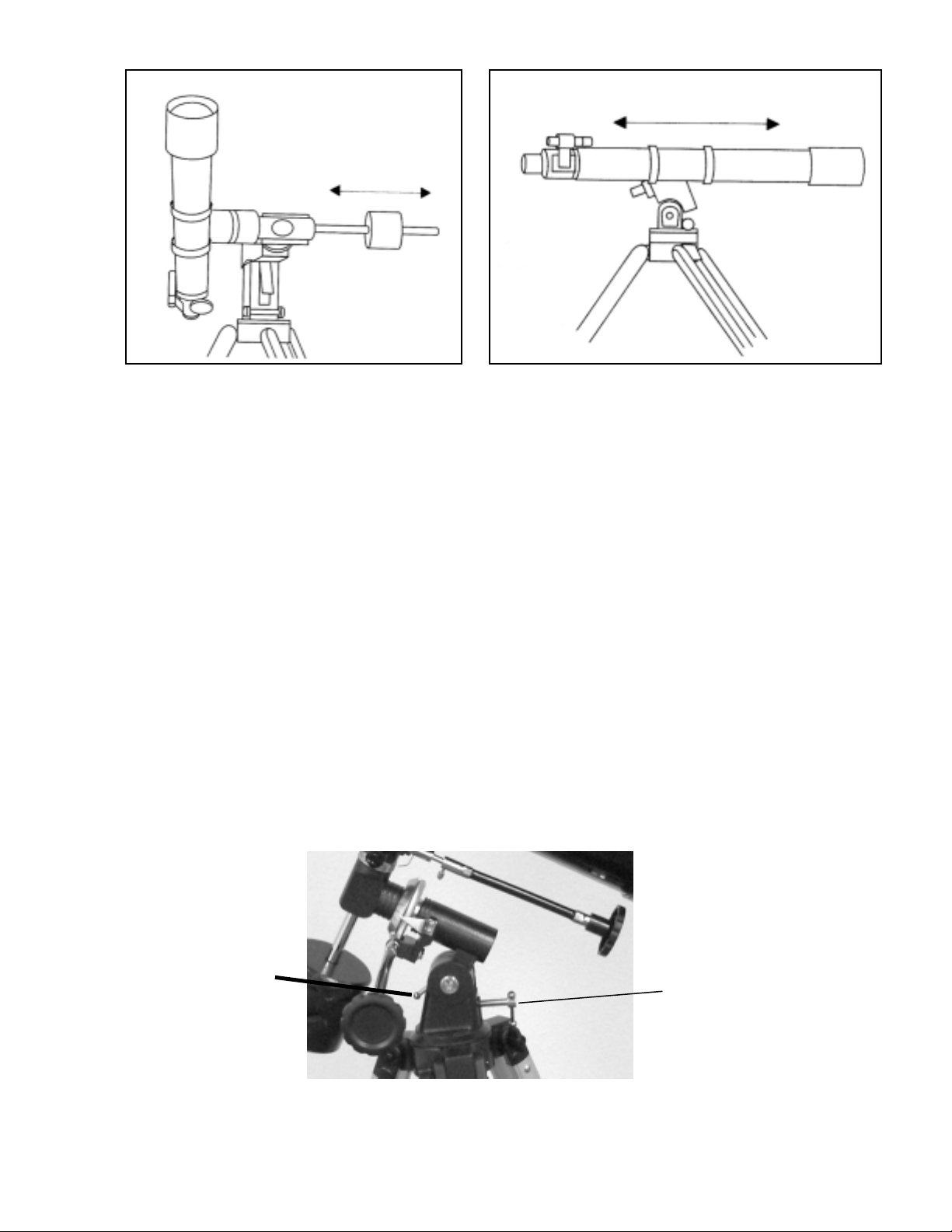
BBaallaanncciinngg tthhee MMoouunntt iinn DDeecc..
The telescope should also be balanced on the declination axis to prevent any sudden motions when the Dec. lock
knob (Fig 2-24) is released. To balance the telescope in Dec.:
1. Release the R.A. locking knob and rotate the telescope so that it is on one side of the mount (i.e., as described in
the previous section on balancing the telescope in R.A.).
2. Lock the R.A. locking knob to hold the telescope in place.
3. Release the Dec. locking knob and rotate the telescope until the tube is parallel to the ground (figure 2-26).
4. Release the tube — GRADUALLY — to see which way it rotates around the declination axis. DO NOT LET
GO OF THE TELESCOPE TUBE COMPLETELY!
5. For the 70EQ, 80EQ, 114EQ, and 127EQ --- while holding the optical tube with one hand, loosen the knurled
screws that hold the telescope tube inside the tube rings and slide the telescope either forwards or backwards
until it remains stationary when the Dec. lock knob is released. There is no adjustment for the 60EQ as it is
fixed in place on the mounting bracket of the mount.
6. Tighten the tube ring screws firmly to hold the telescope in place.
11
Page 12
AAddjjuussttiinngg tthhee EEqquuaattoorriiaall MMoouunnt
In order for a motor drive to track accurately, the telescope’s axis of rotation must be parallel to the Earth’s axis of
rotation, a process known as polar alignment. Polar alignment is achieved NOT by moving the telescope in R.A. or
Dec., but by adjusting the mount vertically, which is called altitude. This section simply covers the correct
movement of the telescope during the polar alignment process. The actual process of polar alignment, that is
making the telescope’s axis of rotation parallel to the Earth’s, is described later in this manual in the section on
“Polar Alignment.”
AAddjjuussttiinngg tthhee MMoouunntt iinn AAllttiittuuddee
• To increase the latitude of the polar axis, loosen the latitude locking bolt slightly -- Figure 2-27.
• To increase or decrease the latitude of the polar axis, tighten or loosen the latitude adjustment screw. Then,
tighten the latitude locking bolt securely. Be careful when turning the screws to avoid hitting your fingers or
having them scrapped on other screws, etc.
The latitude adjustment on the PowerSeeker mount has a range from approximately 20° to 60°.
It is best to always make final adjustments in altitude by moving the mount against gravity (i.e. using the rear
latitude adjustment screw to raise the mount). To do this you should loosen the latitude adjustment screw and then
manually push the front of the mount down as far as it will go. Then tighten the adjustment screw to raise the mount
to the desired latitude.
Figure 2-25
t
Figure 2-26
Latitude Locking Bolt
Figure 2-27
12
Latitude Adjustment
Screw
Page 13
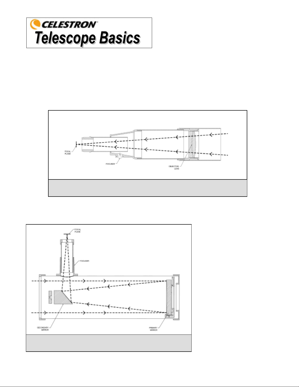
A telescope is an instrument that collects and focuses light. The nature of the optical design determines how the light is focused.
Some telescopes, known as refractors, use lenses, and other telescopes, known as reflectors (Newtonians), use mirrors.
Developed in the early 1600s, the refractor is the oldest telescope design. It derives its name from the method it uses to focus
incoming light rays. The refractor uses a lens to bend or refract incoming light rays, hence the name (see Figure 3-1). Early
designs used single element lenses. However, the single lens acts like a prism and breaks light down into the colors of the
rainbow, a phenomenon known as chromatic aberration. To get around this problem, a two-element lens, known as an
achromat, was introduced. Each element has a different index of refraction allowing two different wavelengths of light to
be focused at the same point. Most two-element lenses, usually made of crown and flint glasses, are corrected for red and
green light. Blue light may still be focused at a slightly different point.
A cutaway view of the light path of the Refractor optical design
Figure 3-1
A Newtonian reflector uses a single concave mirror as its primary. Light enters the tube traveling to the mirror at the back
end. There light is bent forward in the tube to a single point, its focal point. Since putting your head in front of the telescope
to look at the image with an eyepiece would keep the reflector from working, a flat mirror called a diagonal intercepts the
light and points it out the side of the tube at right angles to the tube. The eyepiece is placed there for easy viewing.
Newtonian Reflector telescopes
replace heavy lenses with mirrors to
collect and focus the light, providing
much more light-gathering power for
the money spent. Because the light
path is intercepted and reflected out
to the side, you can have focal
lengths up to 1000mm and still enjoy
a telescope that is relatively compact
and portable. A Newtonian Reflector
telescope offers such impressive
light-gathering characteristics you
can take a serious interest in deep
space astronomy even on a modest
budget. Newtonian Reflector
telescopes do require more care and
maintenance because the primary
mirror is exposed to air and dust.
However, this small drawback does
not hamper this type of telescope’s
Figure 3-2
Cutaway view of the light path of the Newtonian optical design
popularity with those who want an
economical telescope that can still
resolve faint, distant objects.
13
Page 14
n
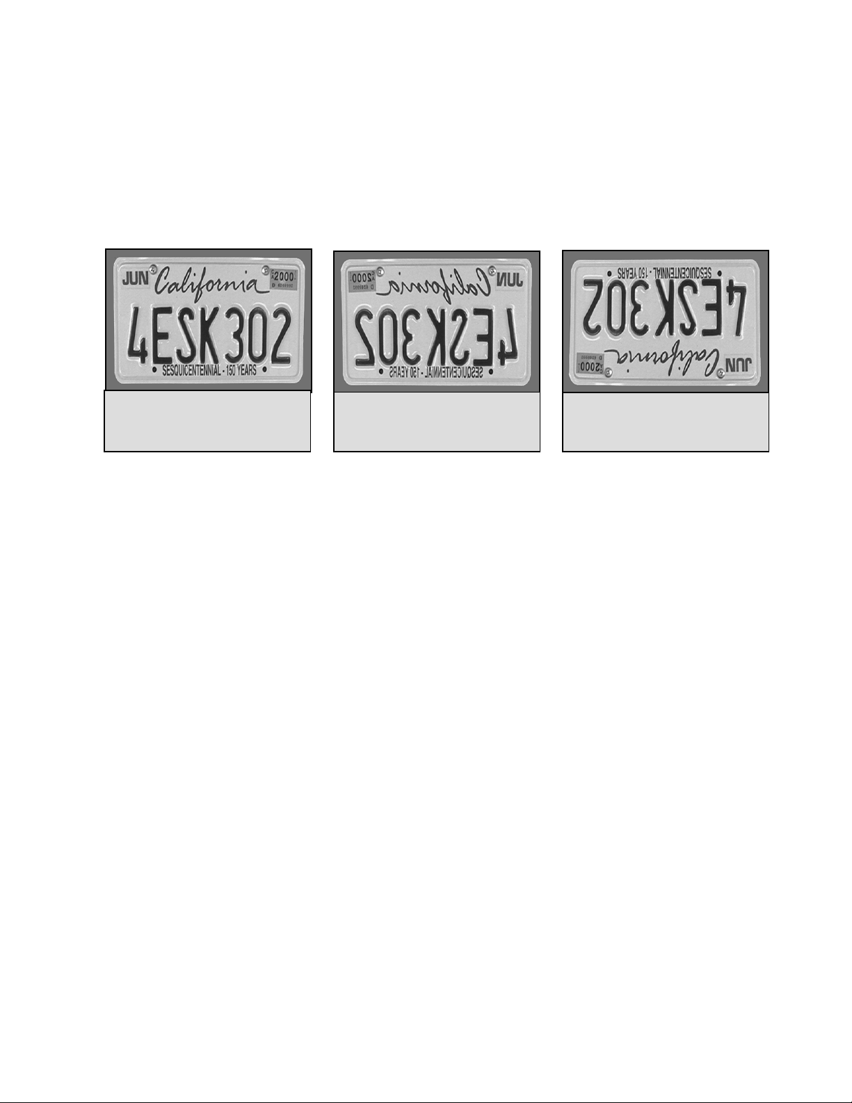
IImmaaggee OOrriieennttaattiioon
The image orientation changes depending on how the eyepiece is inserted into the telescope. When using a star
diagonal with refractors, the image is right-side-up, but reversed from left-to-right (i.e., mirror image). If inserting
the eyepiece directly into the focuser of a refractor (i.e., without the diagonal), the image is upside-down and
reversed from left-to-right (i.e., inverted). However, when using the PowerSeeker refractor and the standard erect
image diagonal, the image is correctly oriented in every aspect.
Newtonian reflectors produce a right-side-up image but the image will appear rotated based on the location of the
eyepiece holder in relation to the ground. However, by using the erect image eyepiece supplied with the
PowerSeeker Newtonians, the image is correctly oriented
Image orientation as seen with the
unaided eye & using erecting
devices on refractors & Newtonians.
FFooccuussiinngg
To focus your refractor or Newtonian telescope, simply turn the focus knob located directly below the eyepiece
holder (see Figures 2-20 and 2-21). Turning the knob clockwise allows you to focus on an object that is farther
than the one you are currently observing. Turning the knob counterclockwise from you allows you to focus on an
object closer than the one you are currently observing.
Note: If you wear corrective lenses (specifically glasses), you may want to remove them when observing with an
eyepiece attached to the telescope. However, when using a camera you should always wear corrective lenses to
ensure the sharpest possible focus. If you have astigmatism, corrective lenses must be worn at all times.
CCaallccuullaattiinngg MMaaggnniiffiiccaattiioonn
You can change the power of your telescope just by changing the eyepiece (ocular). To determine the
magnification of your telescope, simply divide the focal length of the telescope by the focal length of the eyepiece
used. In equation format, the formula looks like this:
Focal Length of Telescope (mm)
Magnification =
Focal Length of Eyepiece (mm)
Let’s say, for example, you are using the 20mm eyepiece that came with your telescope. To determine the
magnification you divide the focal length of your telescope (the PowerSeeker 80EQ for this example has a focal
length of 900mm) by the focal length of the eyepiece, 20mm. Dividing 900 by 20 yields a magnification of 45x.
Reversed from left to right, as
viewed using a Star Diagonal on a
refractor.
Figure 3-3
Inverted image, normal with
Newtonians & as viewed with
eyepiece directly in a refractor.
Although the power is variable, each instrument under average skies has a limit to the highest useful magnification.
The general rule is that 60 power can be used for every inch of aperture. For example, the PowerSeeker 80EQ is
3.1” inches in diameter. Multiplying 3.1 by 80 gives a maximum useful magnification of 189 power. Although this
is the maximum useful magnification, most observing is done in the range of 20 to 35 power for every inch of
aperture which is 62 to 109 times for the PowerSeeker 80EQ telescope. You can determine the magnification for
your telescope the same way.
14
Page 15

DDeetteerrmmiinniinngg FFiieelldd ooff VViieeww
Determining the field of view is important if you want to get an idea of the angular size of the object you are
observing. To calculate the actual field of view, divide the apparent field of the eyepiece (supplied by the eyepiece
manufacturer) by the magnification. In equation format, the formula looks like this:
Apparent Field of Eyepiece
True Angular Field =
Magnification
As you can see, before determining the field of view, you must calculate the magnification. Using the example in
the previous section, we can determine the field of view using the same 20mm eyepiece that is supplied standard
with the PowerSeeker 80EQ telescope. The 20mm eyepiece has an apparent field of view of 50°. Divide the 50° by
the magnification, which is 45 power. This yields an actual (true) field of 1.1°.
To convert degrees to feet at 1,000 yards, which is more useful for terrestrial observing, simply multiply by 52.5.
Continuing with our example, multiply the angular field of 1.1° by 52.5. This produces a linear field width of 58
feet at a distance of one thousand yards.
GGeenneerraall OObbsseerrvviinngg HHiinnttss
When working with any optical instrument, there are a few things to remember to ensure you get the best possible
image.
Never look through window glass. Glass found in household windows is optically imperfect, and as a
y
result, may vary in thickness from one part of a window to the next. This inconsistency can and will
affect the ability to focus your telescope. In most cases you will not be able to achieve a truly sharp
image, while in some cases, you may actually see a double image.
y
Never look across or over objects that are producing heat waves. This includes asphalt parking lots on
hot summer days or building rooftops.
Hazy skies, fog, and mist can also make it difficult to focus when viewing terrestrially. The amount of
y
detail seen under these conditions is greatly reduced.
y If you wear corrective lenses (specifically glasses), you may want to remove them when observing with
an eyepiece attached to the telescope. When using a camera, however, you should always wear
corrective lenses to ensure the sharpest possible focus. If you have astigmatism, corrective lenses must
be worn at all times.
15
Page 16
Up to this point, this manual covered the assembly and basic operation of your telescope. However, to understand your telescope
more thoroughly, you need to know a little about the night sky. This section deals with observational astronomy in general and
includes information on the night sky and polar alignment.
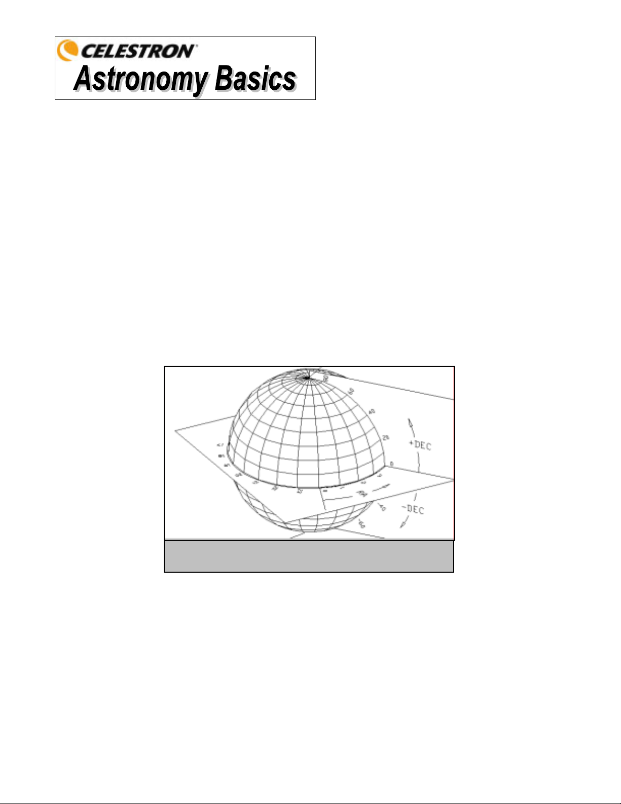
TThhee CCeelleessttiiaall CCoooorrddiinnaattee SSyysstteemm
To help find objects in the sky, astronomers use a celestial coordinate system that is similar to our geographical co-ordinate
system here on Earth. The celestial coordinate system has poles, lines of longitude and latitude, and an equator. For the most
part, these remain fixed against the background stars.
The celestial equator runs 360 degrees around the Earth and separates the northern celestial hemisphere from the southern. Like
the Earth's equator, it bears a reading of zero degrees. On Earth this would be latitude. However, in the sky this is referred to as
declination, or DEC for short. Lines of declination are named for their angular distance above and below the celestial equator.
The lines are broken down into degrees, minutes of arc, and seconds of arc. Declination readings south of the equator carry a
minus sign (-) in front of the coordinate and those north of the celestial equator are either blank (i.e., no designation) or preceded
by a plus sign (+).
The celestial equivalent of longitude is called Right Ascension, or R.A. for short. Like the Earth's lines of longitude, they run
from pole to pole and are evenly spaced 15 degrees apart. Although the longitude lines are separated by an angular distance, they
are also a measure of time. Each line of longitude is one hour apart from the next. Since the Earth rotates once every 24 hours,
there are 24 lines total. As a result, the R.A. coordinates are marked off in units of time. It begins with an arbitrary point in the
constellation of Pisces designated as 0 hours, 0 minutes, 0 seconds. All other points are designated by how far (i.e., how long)
they lag behind this coordinate after it passes overhead moving toward the west.
The celestial sphere seen from the outside showing R.A. and DEC.
Figure 4-1
MMoottiioonn ooff tthhee SSttaarrss
The daily motion of the Sun across the sky is familiar to even the most casual observer. This daily trek is not the Sun
moving as early astronomers thought, but the result of the Earth's rotation. The Earth's rotation also causes the stars to do
the same, scribing out a large circle as the Earth completes one rotation. The size of the circular path a star follows
depends on where it is in the sky. Stars near the celestial equator form the largest circles rising in the east and setting in
the west. Moving toward the north celestial pole, the point around which the stars in the northern hemisphere appear to
rotate, these circles become smaller. Stars in the mid-celestial latitudes rise in the northeast and set in the northwest. Stars
at high celestial latitudes are always above the horizon, and are said to be circumpolar because they never rise and never
set. You will never see the stars complete one circle because the sunlight during the day washes out the starlight.
However, part of this circular motion of stars in this region of the sky can be seen by setting up a camera on a tripod and
opening the shutter for a couple hours. The timed exposure will reveal semicircles that revolve around the pole. (This
description of stellar motions also applies to the southern hemisphere except all stars south of the celestial equator move
around the south celestial pole.)
Page 17
pp
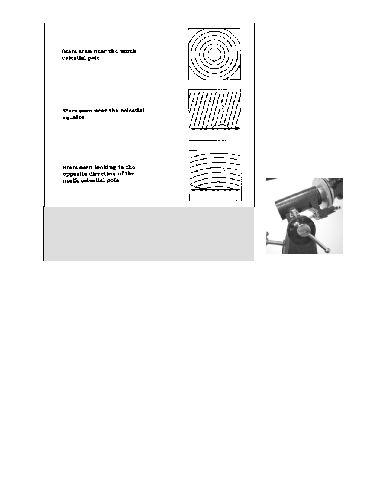
Figure 4-2
All stars appear to rotate around the celestial poles. However, the appearance of this
motion varies depending on where you are looking in the sky. Near the north celestial pole
the stars scribe out recognizable circles centered on the pole (1). Stars near the celestial
equator also follow circular paths around the pole. But, the complete path is interrupted by
the horizon. These appear to rise in the east and set in the west (2). Looking toward the
opposite pole, stars curve or arc in the opposite direction scribing a circle around the
o
osite pole (3).
e
PPoollaarr AAlliiggnnmmeenntt wwiitthh tthhee LLaattiittuuddee SSccaalle
The easiest way to polar align a telescope is with a latitude scale. Unlike other methods that require you to find the celestial pole
by identifying certain stars near it, this method works off of a known constant to determine how high the polar axis should be
pointed. The PowerSeeker equatorial mount can be adjusted from about 20 to 60 degrees (see figure 4-3).
The constant, mentioned above, is a relationship between your latitude and the angular distance the celestial pole is above the
northern (or southern) horizon. The angular distance from the northern horizon to the north celestial pole is always equal to
your latitude. To illustrate this, imagine that you are standing on the north pole, latitude +90°. The north celestial pole, which
has a declination of +90°, would be directly overhead (i.e., 90 above the horizon). Now, let’s say that you move one degree
south — your latitude is now +89° and the celestial pole is no longer directly overhead. It has moved one degree closer toward
the northern horizon. This means the pole is now 89° above the northern horizon. If you move one degree further south, the
same thing happens again. You would have to travel 70 miles north or south to change your latitude by one degree. As you can
see from this example, the distance from the northern horizon to the celestial pole is always equal to your latitude.
If you are observing from Los Angeles, which has a latitude of 34°, then the celestial pole is 34° above the northern horizon.
All a latitude scale does then is to point the polar axis of the telescope at the right elevation above the northern (or southern)
horizon.
To align your telescope:
1. Make sure the polar axis of the mount is pointing due north. Use a landmark that you know faces north.
2. Level the tripod. Leveling the tripod is only necessary if using this method of polar alignment.
3. Adjust the mount in altitude until the latitude indicator points to your latitude. Moving the mount affects the angle the
polar axis is pointing. For specific information on adjusting the equatorial mount, please see the section “Adjusting the
Mount.”
This method can be done in daylight, thus eliminating the need to fumble around in the dark. Although this method does NOT
put you directly on the pole, it will limit the number of corrections you will make when tracking an object.
17
Figure 4-3
Page 18
s
PPooiinnttiinngg aatt PPoollaarriis
This method utilizes Polaris as a guidepost to the north celestial pole. Since Polaris is less than a degree from the celestial
pole, you can simply point the polar axis of your telescope at Polaris. Although this is by no means perfect alignment, it
does get you within one degree. Unlike the previous method, this must be done in the dark when Polaris is visible.
1. Set the telescope up so that the polar axis is pointing north – see Figure 4-6.
2. Loosen the Dec. clutch knob and move the telescope so that the tube is parallel to the polar axis. When this is done,
the declination setting circle will read +90°. If the declination setting circle is not aligned, move the telescope so that
the tube is parallel to the polar axis.
3. Adjust the mount in altitude and/or azimuth until Polaris is in the field of view of the finder.
Remember, while Polar aligning, do NOT move the telescope in R.A. or DEC. You do not want to move the
telescope itself, but the polar axis. The telescope is used simply to see where the polar axis is pointing.
Like the previous method, this gets you close to the pole but not directly on it. The following method helps improve your
accuracy for more serious observations and photography.
FFiinnddiinngg tthhee NNoorrtthh CCeelleessttiiaall PPoollee
In each hemisphere, there is a point in the sky around which all the other stars appear to rotate. These points are called the
celestial poles and are named for the hemisphere in which they reside. For example, in the northern hemisphere all stars
move around the north celestial pole. When the telescope's polar axis is pointed at the celestial pole, it is parallel to the
Earth's rotational axis.
Many methods of polar alignment require that you know how to find the celestial pole by identifying stars in the area. For
those in the northern hemisphere, finding the celestial pole is not too difficult. Fortunately, we have a naked eye star less
than a degree away. This star, Polaris, is the end star in the handle of the Little Dipper. Since the Little Dipper
(technically called Ursa Minor) is not one of the brightest constellations in the sky, it may be difficult to locate from urban
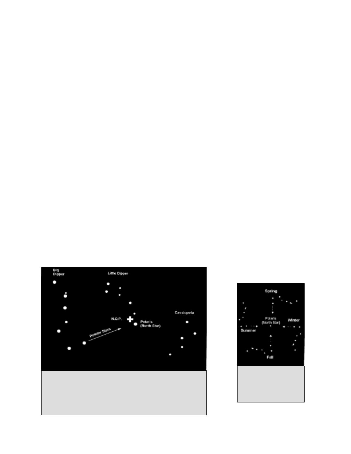
areas. If this is the case, use the two end stars in the bowl of the Big Dipper (the pointer stars). Draw an imaginary line
through them toward the Little Dipper. They point to Polaris (see Figure 4-5). The position of the Big Dipper (Ursa
Major) changes during the year and throughout the course of the night (see Figure 4-4). When the Big Dipper is low in the
sky (i.e., near the horizon), it may be difficult to locate. During these times, look for Cassiopeia (see Figure 4-5).
Observers in the southern hemisphere are not as fortunate as those in the northern hemisphere. The stars around the south
celestial pole are not nearly as bright as those around the north. The closest star that is relatively bright is Sigma Octantis.
This star is just within naked eye limit (magnitude 5.5) and lies about 59 arc minutes from the pole.
Definition:The north celestial pole is the point in the northern hemisphere around which all stars appear to rotate. The
counterpart in the southern hemisphere is referred to as the south celestial pole.
Figure 4-5
The two stars in the front of the bowl of the Big Dipper point to Polaris
which is less than one degree from the true (north) celestial pole.
Cassiopeia, the “W” shaped constellation, is on the opposite side of the
pole from the Big Dipper. The North Celestial Pole (N.C.P.) is marked
by the “+” sign.
Figure 4-4
The position of the Big
Dipper changes throughout
the year and the night.
18
Page 19
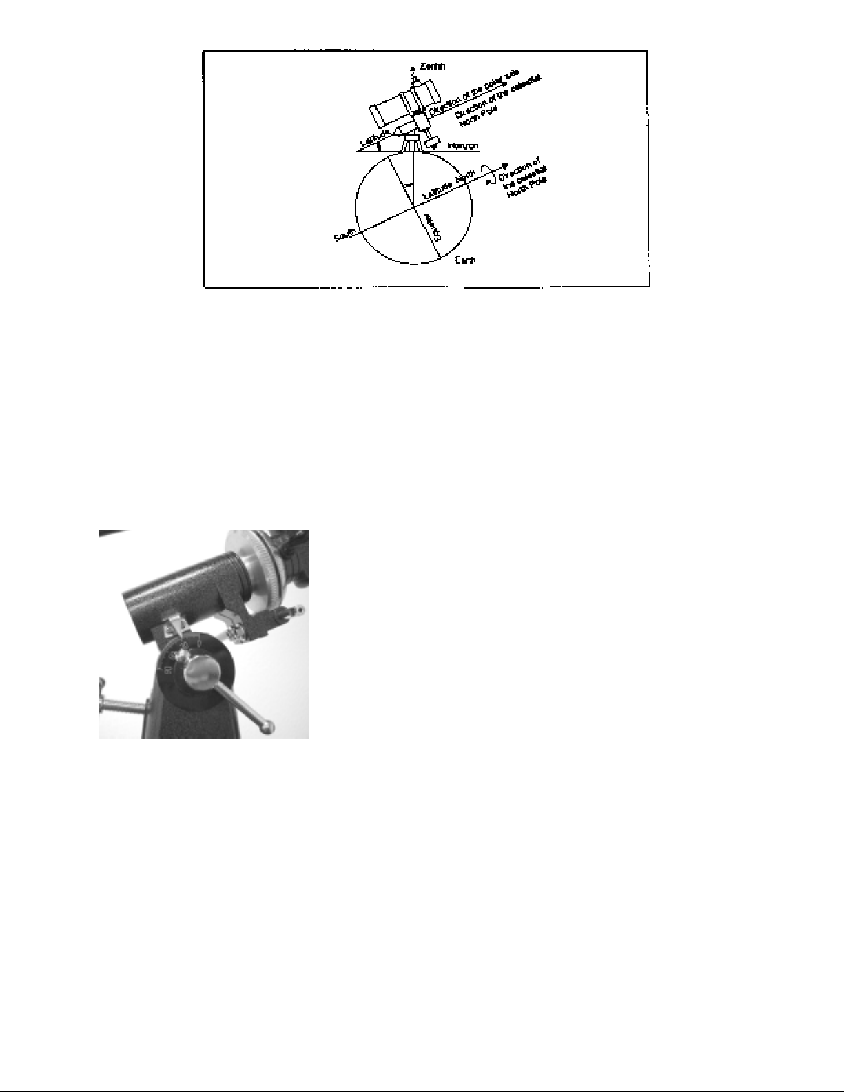
Figure 4-6
Aligning the equatorial mount to the polar axis of the Earth
PPoollaarr AAlliiggnnmmeenntt iinn tthhee SSoouutthheerrnn HHeemmiisspphheerree
Polar alignment to the South Celestial Pole (SCP) is a little more challenging due to the fact that there is no very
bright star close to it like Polaris is in the NCP. There are various ways to polar align your telescope and for casual
observing the methods below are adequate and will get you reasonably close to the SCP.
Polar Alignment with the Latitude Scale
The easiest way to polar align a telescope is with a latitude scale. Unlike other methods that require you to find the
celestial pole by identifying certain stars near it, this method works off of a known constant to determine how high
the polar axis should be pointed.
The constant, mentioned above, is a relationship between your latitude and
the angular distance the celestial pole is above the southern horizon. The
angular distance from the southern horizon to the south celestial pole is
always equal to your latitude. To illustrate this, imagine that you are
standing on the south pole, latitude -90°. The south celestial pole, which
has a declination of -90°, would be directly overhead (i.e., 90° above the
horizon). Now, let’s say that you move one degree north — your latitude is
now -89° and the celestial pole is no longer directly overhead. It has moved
one degree closer toward the southern horizon. This means the pole is now
89° above the southern horizon. If you move one degree further north, the
same thing happens again. You would have to travel 70 miles north or south
to change your latitude by one degree. As you can see from this example,
the distance from the southern horizon to the celestial pole is always equal
to your latitude.
Figure 4-7
If you are observing from Sydney, which has a latitude of -34°, then the celestial pole is 34° above the southern
horizon. All a latitude scale does then is to point the polar axis of the telescope at the right elevation above the
southern horizon. To align your telescope:
1. Make sure the polar axis of the mount is pointing due south. Use a landmark that you know faces south.
2. Level the tripod. Leveling the tripod is only necessary if using this method of polar alignment.
3. Adjust the mount in altitude until the latitude indicator points to your latitude. Moving the mount affects the
angle the polar axis is pointing. For specific information on adjusting the equatorial mount, please see the
section “Adjusting the Mount” in your telescope manual.
4. If the above is done correctly, you should be able to observe near the pole through the finderscope and a low
power eyepiece.
This method can be done in daylight, thus eliminating the need to fumble around in the dark. Although this method
does NOT put you directly on the pole, it will limit the number of corrections you will make when tracking an
object.
19
Page 20
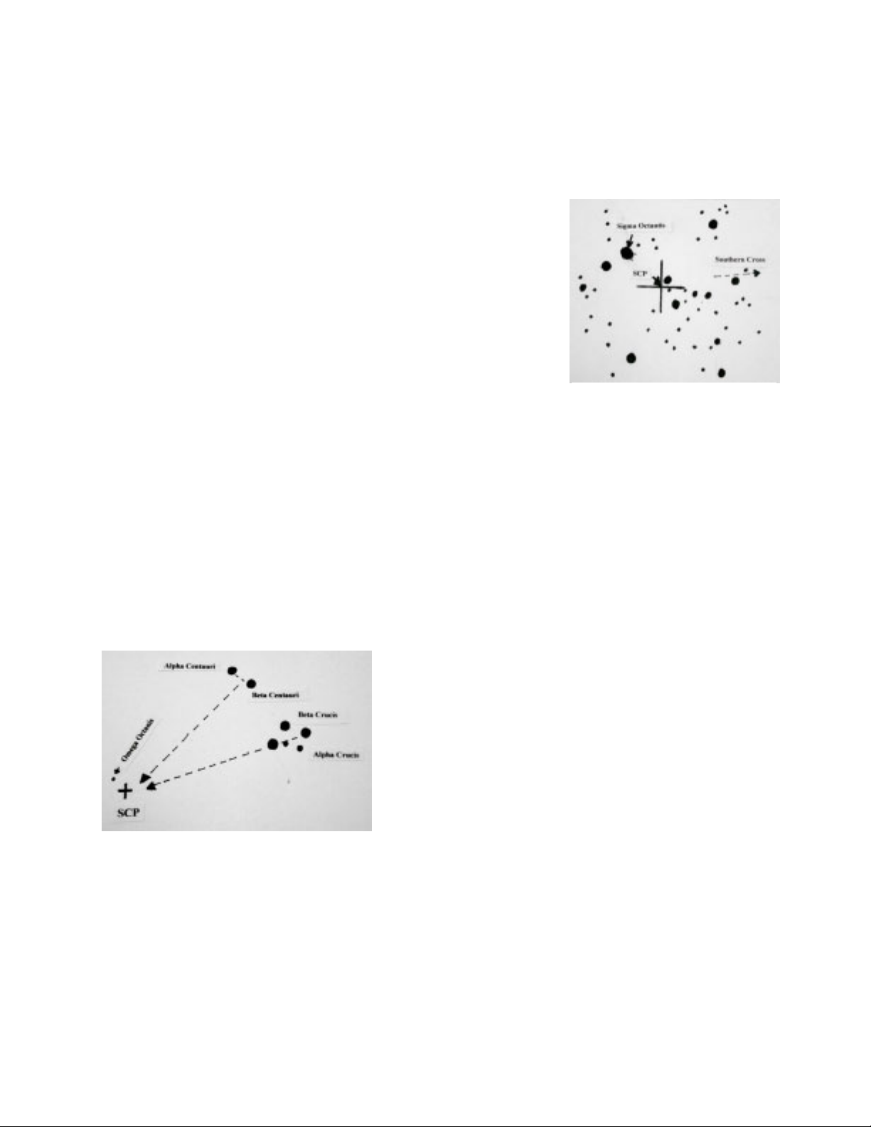
Pointing at Sigma Octantis
This method utilizes Sigma Octantis as a guidepost to the celestial pole. Since Sigma Octantis is about 1° degree
from the south celestial pole, you can simply point the polar axis of your telescope at Sigma Octantis. Although this
is by no means perfect alignment, it does get you within one degree. Unlike the previous method, this must be done
in the dark when Sigma Octantis is visible. Sigma Octantis has a magnitude of 5.5 and may be difficult to see and a
binocular may be helpful as well as the finderscope.
1. Set the telescope up so that the polar axis is pointing south.
2. Loosen the DEC clutch knob and move the telescope so that the tube is
parallel to the polar axis. When this is done, the declination setting circle
will read 90°. If the declination setting circle is not aligned, move the
telescope so that the tube is parallel to the polar axis.
3. Adjust the mount in altitude and/or azimuth until Sigma Octantis is in the
field of view of the finder.
4. If the above is done correctly, you should be able to observe near the pole
through the finderscope and a low power eyepiece.
Remember, while Polar aligning, do NOT move the telescope in R.A. or
DEC. You do not want to move the telescope itself, but the polar axis. The
telescope is used simply to see where the polar axis is pointing.
Like the previous method, this gets you close to the pole but not directly on it.
FFiinnddiinngg tthhee SSoouutthh CCeelleessttiiaall PPoollee ((SSCCPP))
This method helps improve your polar alignment and gets you closer to the pole that the above methods. This will
improve your accuracy for more serious observations and photography.
In each hemisphere, there is a point in the sky around which all the other stars appear to rotate. These points are
called the celestial poles and are named for the hemisphere in which they reside. For example, in the southern
hemisphere all stars move around the south celestial pole. When the telescope's polar axis is pointed at the celestial
pole, it is parallel to the Earth's rotational axis.
Many methods of polar alignment require that you know how to
find the celestial pole by identifying stars in the area. Observers in
the southern hemisphere are not as fortunate as those in the
northern hemisphere. The stars around the south celestial pole are
not nearly as bright as those around the north celestial pole. The
closest star that is relatively bright is Sigma Octantis. This star is
just within naked eye limit (magnitude 5.5) and lies about 1° from
the south celestial pole but can be difficult to locate.
Figure 4-8
Figure 4-9
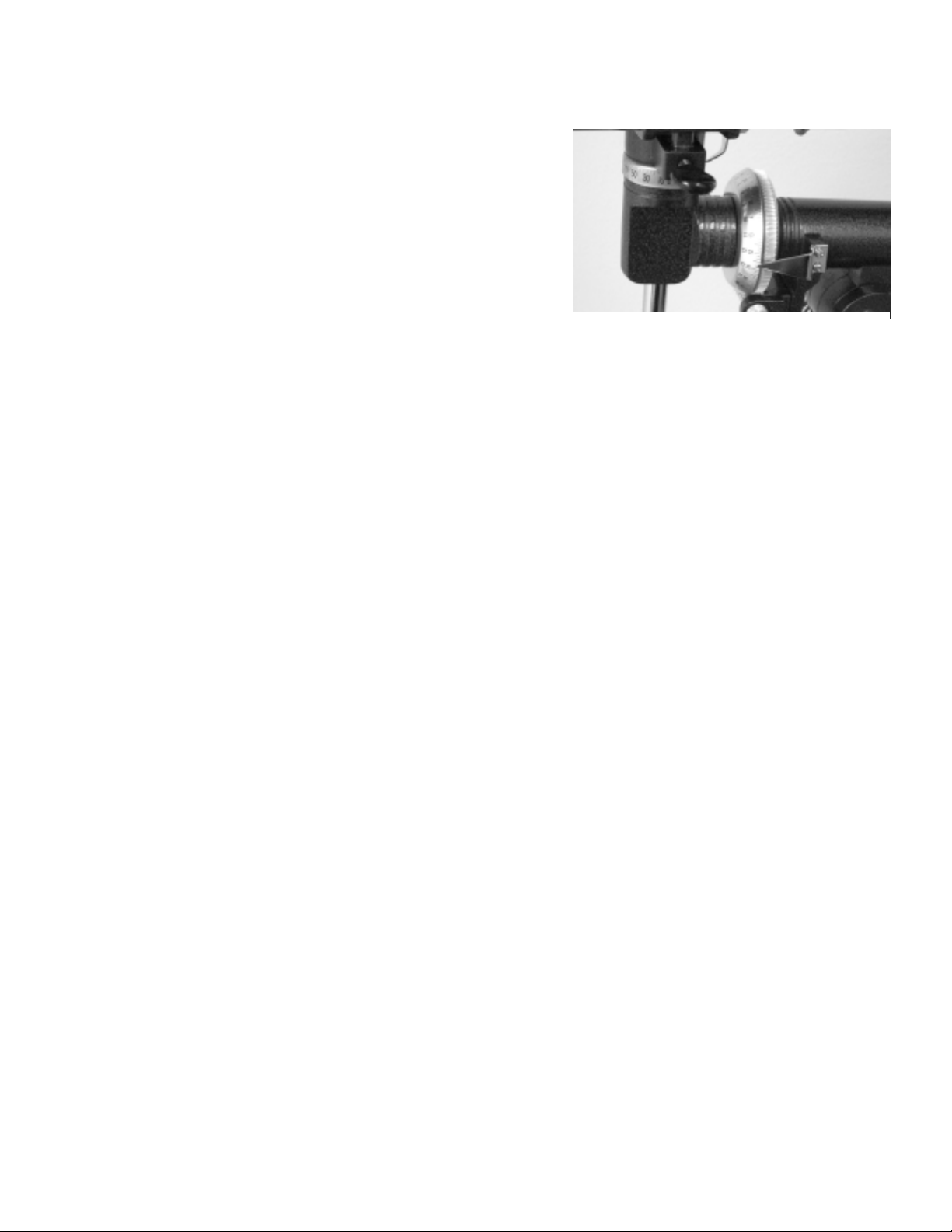
Therefore, with this method, you will use star patterns to find the south celestial pole. Draw an imaginary line
toward the SCP through Alpha Crucis and Beta Crucis (which are in the Southern Cross). Draw another imaginary
line toward the SCP at a right angle to a line connecting Alpha Centauri and Beta Centauri. The intersecting of
these two imaginary lines will point you close to the south celestial pole.
20
Page 21
AAlliiggnniinngg tthhee SSeettttiinngg CCiirrcclleess
Before you can use the setting circles to find objects in the sky you
need to align the R.A. setting circle which is incremented in minutes.
The declination setting circle is scaled in degrees and it is factory set
and should not need any adjustments. On the R.A. setting circle there
are two sets of numbers on the dial – one for the northern hemisphere
(top) and one for the southern hemisphere (bottom).
In order to align the R.A. setting circle, you will need to know the
names of a few of the brightest stars in the sky. If you don’t, they can
be learned by using the Celestron Sky Maps (#93722) or consulting a
current astronomy magazine.
To align the R.A. setting circle:
1. Locate a bright star near the celestial equator. The farther you are from the celestial pole the better your reading
on the R.A. setting circle will be. The star you choose to align the setting circle with should be a bright one
whose coordinates are known and easy to look up.
2. Center the star in the finderscope.
3. Look through the main telescope and see if the star is in the field. If not, find it and center it.
4. Look up the coordinates of the star.
5. Rotate the circle until the proper coordinate lines up with the R.A. indicator. The R.A. setting circle should
rotate freely.
Dec. Circle @ top and R.A. Circle @ bottom
Figure 4-10
NOTE: Because the R.A. setting circle does NOT move as the telescope moves in R.A., the setting circle must
be aligned each time you want to use it to find an object. However, you do not need to use a star each
time. Instead, you can use the coordinates of the object you are currently observing.
Once the circles are aligned you can use them to find any objects with known coordinates. The accuracy of your
setting circles is directly related to the accuracy of your polar alignment.
1. Select an object to observe. Use a seasonal star chart to make sure the object you chose is above the horizon.
As you become more familiar with the night sky, this will no longer be necessary.
2. Look up the coordinates in a star atlas or reference book.
3. Hold the telescope and release the Dec. lock knob.
4. Move the telescope in declination until the indicator is pointing at the correct declination coordinate.
5. Lock the Dec. lock knob to prevent the telescope from moving.
6. Hold the telescope and release the R.A. lock knob.
7. Move the telescope in R.A. until the indicator points to the correct coordinate.
8. Lock the R.A. lock knob to prevent the telescope from slipping in R.A.
9. Look through the finderscope to see if you have located the object and center the object in the finderscope.
10. Look in the main optics and the object should be there. For some of the fainter objects, you may not be able to
see them in the finderscope. When this happens, it is a good idea to have a star chart of the area so that you can
“star hop” through the field to your target.
11. This process can be repeated for each object throughout any given night.
21
Page 22
MMoottoorr DDrriivvee
To allow tracking of celestial objects, Celestron offers a single axis DC motor drive for the PowerSeeker equatorial
mount. Once polar aligned, the motor drive will accurately track objects in Right Ascension as they move across the
sky. Only minor adjustments in Declination will be necessary to keep celestial objects centered in the eyepiece for
long periods of time. Some models come standard with this motor drive and it is sold as an optional accessory
( Model # 93514 ) for other models.
Installation of the Motor Drive – for those purchasing it as an optional accessory.
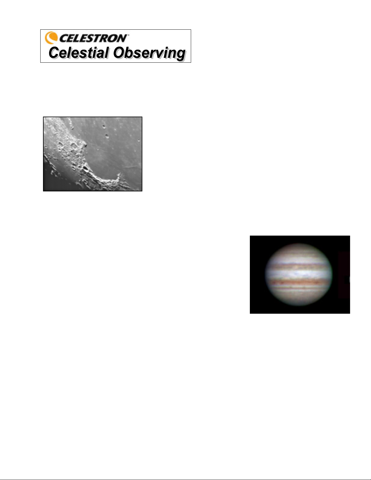
The motor drive attaches to the PowerSeeker equatorial mount via a flexible coupler that mounts to the R.A. slow
motion shaft and a motor bracket that holds the motor in place. To install the motor drive see the description and
photos below:
1. Make sure the R.A. slow motion cable is attached to the R.A. shaft opposite of the latitude scale.
2. Remove the Allen head bolt located on the side of the polar shaft.
3. Slide the open end of the flexible motor coupler over the R.A. shaft. Make sure that the screw on the flexible
motor coupler is positioned over the flat portion of the R.A. shaft.
4. Tighten the motor coupler screw with a flathead screwdriver.
5. Rotate the motor on the shaft until the slotted cutout on the motor bracket aligns with the threaded hole in the
center of the mount’s latitude pivot axis.
6. Place the Allen head bolt through the motor bracket and thread it into the hole on the side of the pivot axis.
Then, tighten the bolt with an Allen wrench.
Flexible Motor Coupler
Mounting
Screws
Figure 4-11 Figure 4-12
Operating the Motor Drive
Motor Bracket
Allen Head Bolt
The motor drive is powered by one 9-volt alkaline battery. This can power the drive for up to 40 hours, depending
on motor speed setting and ambient temperature. The battery should be installed already but if not (or replacing the
battery), unscrew the two mounting screws – Figure 4-11. Remove the control panel plate from the motor assembly
and then remove the motor bracket from the motor. Then, you will be able to get to the battery connected to cables
for installing or replacing. Finally, reverse all steps to remount the motor drive to the mount.
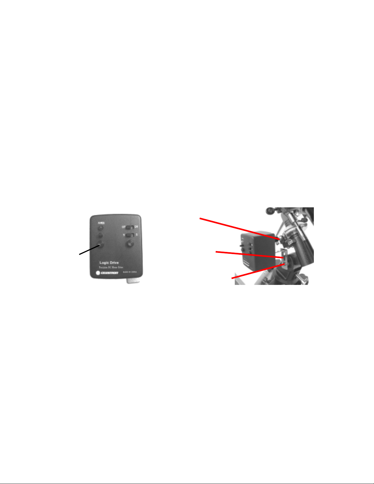
The motor drive is equipped with a speed rate regulator (in Figure 4-11 it is above the mounting screw) that allows
the motor drive to track at a faster or slower speed. This is useful when observing non-stellar objects like the moon
or Sun which travel at a slightly different rate than the stars. To change the speed of the motor, slide the On/Off
switch to the “ON” position and the red power indicator light will illuminate. Then, turn the speed rate regulator
knob clockwise to increase the speed of the motor and counterclockwise to decrease the speed.
To determine the proper rate of speed, the telescope should be roughly polar aligned. Find a star on the celestial
equator (approximately 0° declination) and center it in a low power eyepiece. Now turn the drive on and let the
telescope track for 1 or 2 minutes. If after a few minutes, the star drifts to the West, the motor is tracking too slowly
and you should increase the motor speed. If the star is drifting to the East, then decrease the motor speed. Repeat
this process until the star remains centered in the eyepiece for several minutes. Remember to ignore any star drift in
declination.
The drive also has a “N/S” switch to be set if operating in the Northern or Southern Hemisphere.
22
Page 23
With your telescope set up, you are ready to use it for observing. This section covers visual observing hints for both
solar system and deep sky objects as well as general observing conditions which will affect your ability to observe.
OObbsseerrvviinngg tthhee MMoooonn
Lunar Observing Hints
To increase contrast and bring out detail on the lunar surface, use optional filters. A yellow filter works well at
improving contrast while a neutral density or polarizing filter will reduce overall surface brightness and glare.
OObbsseerrvviinngg tthhee PPllaanneettss
Other fascinating targets include the five naked eye planets. You can see Venus
go through its lunar-like phases. Mars can reveal a host of surface detail and
one, if not both, of its polar caps. You will be able to see the cloud belts of
Jupiter and the great Red Spot (if it is visible at the time you are observing). In
addition, you will also be able to see the moons of Jupiter as they orbit the giant
planet. Saturn, with its beautiful rings, is easily visible at moderate power
Often, it is tempting to look at the Moon when it is full. At this time, the
face we see is fully illuminated and its light can be overpowering. In
addition, little or no contrast can be seen during this phase.
One of the best times to observe the Moon is during its partial phases
(around the time of first or third quarter). Long shadows reveal a great
amount of detail on the lunar surface. At low power you will be able to
see most of the lunar disk at one time. Change to optional eyepieces for
higher power (magnification) to focus in on a smaller area.
.
Planetary Observing Hints
y Remember that atmospheric conditions are usually the limiting factor
on how much planetary detail will be visible. So, avoid observing the
planets when they are low on the horizon or when they are directly over a source of radiating heat, such as
a rooftop or chimney. See the "Seeing Conditions" section later in this section.
y To increase contrast and bring out detail on the planetary surface, try using Celestron eyepiece filters.
OObbsseerrvviinngg tthhee SSuunn
Although overlooked by many amateur astronomers, solar observation is both rewarding and fun. However,
because the Sun is so bright, special precautions must be taken when observing our star so as not to damage your
eyes or your telescope.
For safe solar viewing, use a proper solar filter that reduces the intensity of the Sun's light, making it safe to view.
With a filter you can see sunspots as they move across the solar disk and faculae, which are bright patches seen near
the Sun's edge.
y The best time to observe the Sun is in the early morning or late afternoon when the air is cooler.
y To center the Sun without looking into the eyepiece, watch the shadow of the telescope tube until it forms a
circular shadow.
23
Page 24
s
OObbsseerrvviinngg DDeeeepp--SSkkyy OObbjjeecctts
Deep-sky objects are simply those objects outside the boundaries of our solar system. They include star clusters,
planetary nebulae, diffuse nebulae, double stars and other galaxies outside our own Milky Way. Most deep-sky
objects have a large angular size. Therefore, low-to-moderate power is all you need to see them. Visually, they are
too faint to reveal any of the color seen in long exposure photographs. Instead, they appear black and white. And,
because of their low surface brightness, they should be observed from a dark-sky location. Light pollution around
large urban areas washes out most nebulae making them difficult, if not impossible, to observe. Light Pollution
Reduction filters help reduce the background sky brightness, thus increasing contrast.
SSeeeeiinngg CCoonnddiittiioonnss
Viewing conditions affect what you can see through your telescope during an observing session. Conditions include
transparency, sky illumination, and seeing. Understanding viewing conditions and the effect they have on observing
will help you get the most out of your telescope.
Transparency
Transparency is the clarity of the atmosphere which is affected by clouds, moisture, and other airborne particles.
Thick cumulus clouds are completely opaque while cirrus can be thin, allowing the light from the brightest stars
through. Hazy skies absorb more light than clear skies making fainter objects harder to see and reducing contrast on
brighter objects. Aerosols ejected into the upper atmosphere from volcanic eruptions also affect transparency. Ideal
conditions are when the night sky is inky black.
Sky Illumination
General sky brightening caused by the Moon, aurora, natural airglow, and light pollution greatly affect transparency.
While not a problem for the brighter stars and planets, bright skies reduce the contrast of extended nebulae making
them difficult, if not impossible to see. To maximize your observing, limit deep sky viewing to moonless nights far
from the light polluted skies found around major urban areas. LPR filters enhance deep sky viewing from light
polluted areas by blocking unwanted light while transmitting light from certain deep sky objects. You can, on the
other hand, observe planets and stars from light polluted areas or when the Moon is out.
Seeing
Seeing conditions refers to the stability of the atmosphere and directly affects the amount of fine detail seen in
extended objects. The air in our atmosphere acts as a lens which bends and distorts incoming light rays. The
amount of bending depends on air density. Varying temperature layers have different densities and, therefore, bend
light differently. Light rays from the same object arrive slightly displaced creating an imperfect or smeared image.
These atmospheric disturbances vary from time-to-time and place-to-place. The size of the air parcels compared to
your aperture determines the "seeing" quality. Under good seeing conditions, fine detail is visible on the brighter
planets like Jupiter and Mars, and stars are pinpoint images. Under poor seeing conditions, images are blurred and
stars appear as blobs.
The conditions described here apply to both visual and photographic observations.
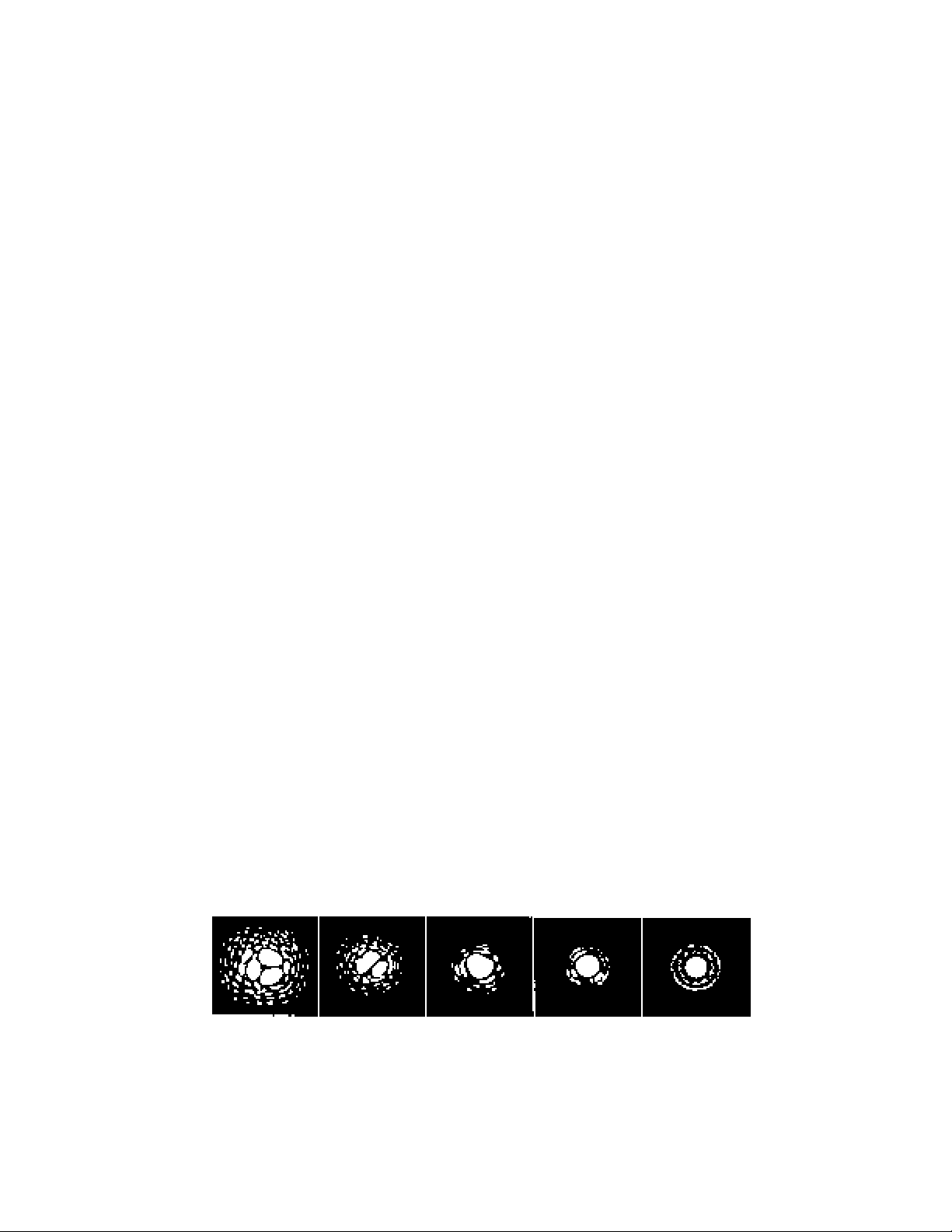
Figure 5-1
Seeing conditions directly affect image quality. These drawings represent a point
source (i.e., star) under bad seeing conditions (left) to excellent conditions (right).
Most often, seeing conditions produce images that lie somewhere between these two
extremes.
24
Page 25
The PowerSeeker series of telescopes was designed for visual observing. After looking at the night sky for a while
you may want to try your hand at photography of it. There are several forms of photography possible with your
telescope for celestial as well as terrestrial pursuits. Below is just a very brief discussion of some of the methods of
photography available and suggest you search out various books for detailed information on the subject matter.
As a minimum you will need a digital camera or a 35mm SLR camera. Attach your camera to the telescope with:
y Digital camera – you will need the Universal Digital Camera Adapter (# 93626). The adapter allows the
camera to be mounted rigidly for terrestrial as well as prime focus astrophotography.
y 35mm SLR camera – you will need to remove your lens from the camera and attach a T-Ring for your
specific camera brand. Then, you will need a T-Adapter (# 93625) to attach on one end to the T-Ring and
the other end to the telescope focus tube. Your telescope is now the camera lens.
SShhoorrtt EExxppoossuurree PPrriimmee FFooccuuss PPhhoottooggrraapphhyy
Short exposure prime focus photography is the best way to begin imaging celestial objects. It is done by attaching
your camera to the telescope as described in the paragraph above. A couple of points to keep in mind:
y Polar align the telescope and start the optional motor drive for tracking.
y You can image the Moon as well as the brighter planets. You will have to experiment with various settings
and exposure times. Much information can be obtained from your camera instruction manual which can
supplement what you can find in detailed books on the subject matter.
y Do your photography from a dark sky observing site if possible.
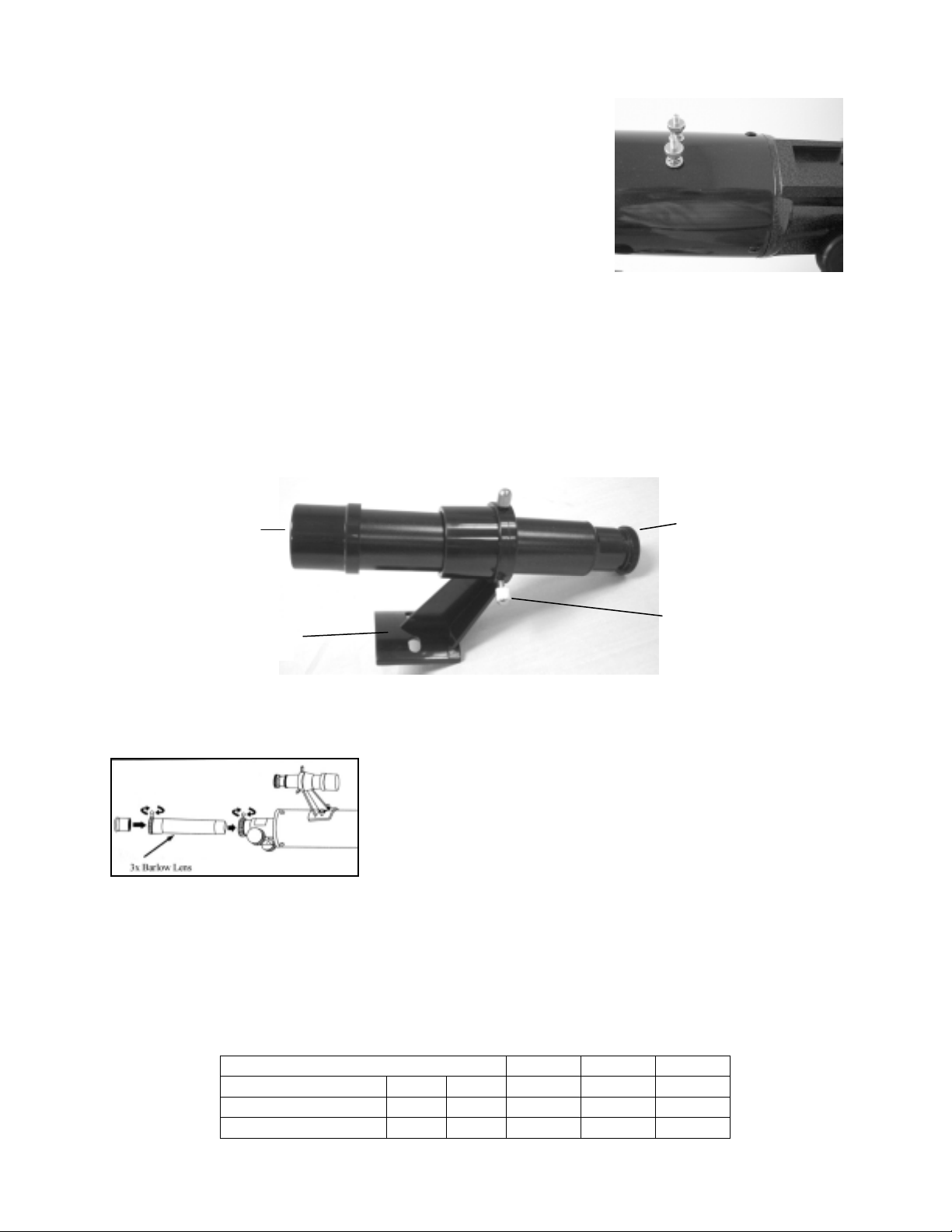
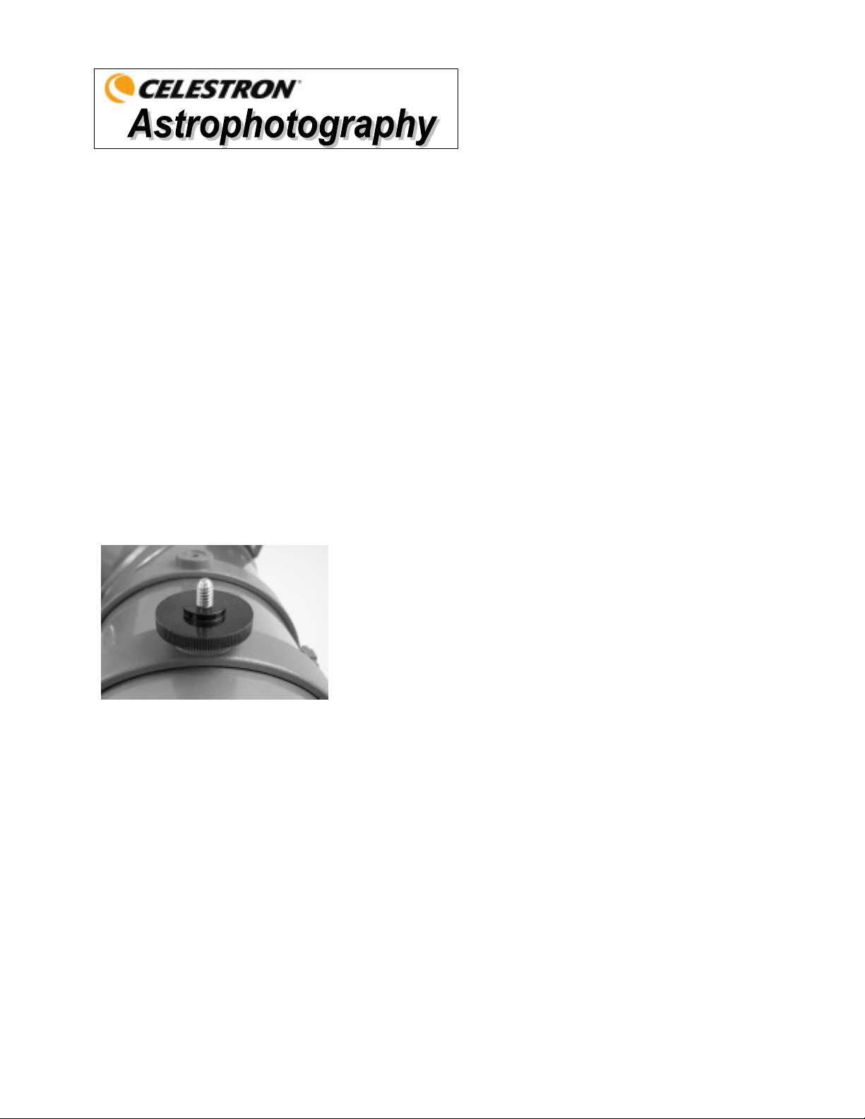
PPiiggggyybbaacckk PPhhoottooggrraapphhyy
For the 70EQ, 80EQ, 114EQ, and 127EQ telescopes, piggyback
photography is done with a camera and its normal lens riding on top of the
telescope. Through this method you can capture entire constellations and
record large scale nebulae. You attach your camera to the piggyback
adapter screw (Figure 6-1) located on the top of the tube mounting ring
(your camera will have a threaded hole on the bottom to fit this screw).
You will need to polar align the telescope and start the optional motor
drive for tracking
Figure 6-1
.
PPllaanneettaarryy && LLuunnaarr PPhhoottooggrraapphhyy wwiitthh SSppeecciiaall IImmaaggeerrss
During the last few years a new technology has evolved which makes taking superb images of the planets and moon
relatively easy and the results are truly amazing. Celestron offers the NexImage (# 93712) which is a special camera
and included is software for image processing. You can capture planetary images your first night out which rivals
what professionals were doing with large telescopes just a few short years ago.
CCCCDD IImmaaggiinngg ffoorr DDeeeepp SSkkyy OObbjjeeccttss
Special cameras have been developed for taking images of deep sky images. These have evolved over the last
several years to become much more economical and amateurs can take fantastic images. Several books have been
written on how to get the best images possible. The technology continues to evolve with better and easier to use
products on the market.
TTeerrrreessttrriiaall PPhhoottooggrraapphhyy
Your telescope makes an excellent telephoto lens for terrestrial (land) photography. You can take images of various
scenic views, wildlife, nature, and just about anything. You will have to experiment with focusing, speeds, etc. to
get the best image desired. You can adapt your camera per the instructions at the top of this page.
25
Page 26
While your telescope requires little maintenance, there are a few things to remember that will ensure your telescope
performs at its best.
CCaarree aanndd CClleeaanniinngg ooff tthhee OOppttiiccss
Occasionally, dust and/or moisture may build up on the objective lens or primary mirror depending on which type of
telescope you have. Special care should be taken when cleaning any instrument so as not to damage the optics.
If dust has built up on the optics, remove it with a brush (made of camel’s hair) or a can of pressurized air. Spray at an
angle to the glass surface for approximately two to four seconds. Then, use an optical cleaning solution and white tissue
paper to remove any remaining debris. Apply the solution to the tissue and then apply the tissue paper to the optics.
Low pressure strokes should go from the center of the lens (or mirror) to the outer portion. Do NOT rub in circles!
You can use a commercially made lens cleaner or mix your own. A good cleaning solution is isopropyl alcohol mixed
with distilled water. The solution should be 60% isopropyl alcohol and 40% distilled water. Or, liquid dish soap diluted
with water (a couple of drops per one quart of water) can be used.
Occasionally, you may experience dew build-up on the optics of your telescope during an observing session. If you want
to continue observing, the dew must be removed, either with a hair dryer (on low setting) or by pointing the telescope at
the ground until the dew has evaporated.
If moisture condenses on the inside of the optics, remove the accessories from the telescope. Place the telescope in a
dust-free environment and point it down. This will remove the moisture from the telescope tube.
To minimize the need to clean your telescope, replace all lens covers once you have finished using it. Since the cells are
NOT sealed, the covers should be placed over the openings when not in use. This will prevent contaminants from
entering the optical tube.
Internal adjustments and cleaning should be done only by the Celestron repair department. If your telescope is in need of
internal cleaning, please call the factory for a return authorization number and price quote.
CCoolllliimmaattiioonn ooff aa NNeewwttoonniiaann
The optical performance of most Newtonian reflecting telescopes can be optimized by re-collimating (aligning) the
telescope's optics, as needed. To collimate the telescope simply means to bring its optical elements into balance. Poor
collimation will result in optical aberrations and distortions.
Before collimating your telescope, take time to familiarize yourself with all its components. The primary mirror is the
large mirror at the back end of the telescope tube. This mirror is adjusted by loosening and tightening the three screws,
placed 120 degrees apart, at the end of the telescope tube. The secondary mirror (the small, elliptical mirror under the
focuser, in the front of the tube) also has three adjustment screws (you will need optional tools (described below) to
perform collimation. To determine if your telescope needs collimation first point your telescope toward a bright wall or
blue sky outside.
Aligning the Secondary Mirror
The following describes the procedure for daytime collimation of your telescope using the optional Newtonian
Collimation Tool (#94183) offered by Celestron. To collimate the telescope without the Collimation Tool, read the
following section on night time star collimation. For very precise collimation, the optional Collimation Eyepiece 1 ¼” (#
94182) is offered.
If you have an eyepiece in the focuser, remove it. Rack the focuser tube in completely, using the focusing knobs, until
its silver tube is no longer visible. You will be looking through the focuser at a reflection of the secondary mirror,
projected from the primary mirror. During this step, ignore the silhouetted reflection from the primary mirror. Insert the
collimating cap into the focuser and look through it. With the focus pulled in all the way, you should be able to see the
entire primary mirror reflected in the secondary mirror. If the primary mirror is not centered in the secondary mirror,
adjust the secondary mirror screws by alternately tightening and loosening them until the periphery of the primary mirror
is centered in your view. DO NOT loosen or tighten the center screw in the secondary mirror support, because it
maintains proper mirror position.
26
Page 27
Aligning the Primary Mirror
Now adjust the primary mirror screws to re-center the reflection of the small secondary mirror, so it’s silhouetted
against the view of the primary. As you look into the focuser, silhouettes of the mirrors should look concentric.
Repeat steps one and two until you have achieved this.
Remove the collimating cap and look into the focuser, where you should see the reflection of your eye in the
secondary mirror.
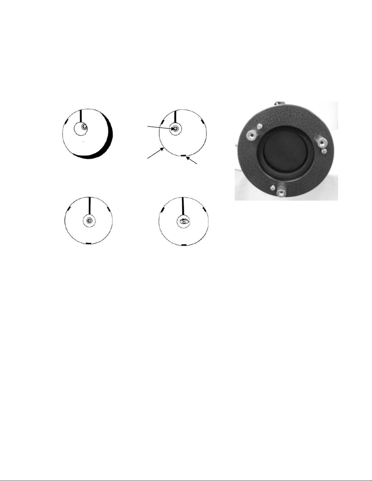
Newtonian collimation views as seen through the focuser using the collimation cap
Secondary mirror needs adjustment.
Secondary
Mirror
Primary mirror needs adjustment.
Primary
Mirror
Mirror Clip
Both mirrors aligned with the collimating
cap in the focuser.
Both mirrors aligned with your eye
looking into the focuser.
Figure 7-1 PowerSeeker 114EQ
Night Time Star Collimating
After successfully completing daytime collimation, night time star collimation can be done by closely adjusting the
primary mirror while the telescope tube is on its mount and pointing at a bright star. The telescope should be set up
at night and a star's image should be studied at medium to high power (30-60 power per inch of aperture). If a nonsymmetrical focus pattern is present, then it may be possible to correct this by re-collimating only the primary
mirror.
Procedure (Please read this section completely before beginning):
To star collimate in the Northern Hemisphere, point at a stationary star like the North Star (Polaris). It can be found
in the north sky, at a distance above the horizon equal to your latitude. It’s also the end star in the handle of the
Little Dipper. Polaris is not the brightest star in the sky and may even appear dim, depending upon your sky
conditions. For the Southern Hemisphere, point at Sigma Octantis.
Prior to re-collimating the primary mirror, locate the collimation screws on the rear of the telescope tube. The rear
cell (shown in Figure 7-1) has three large thumbscrews (on some models they are not thumbscrews) which are used
for collimation and three small thumbscrews which are used to lock the mirror in place. The collimation screws tilt
the primary mirror. You will start by loosening the small locking screws a few turns each. Normally, motions on
the order of an
the large collimation screws. Turn one collimation screw at a time and with a collimation tool or eyepiece see how
the collimation is affected (see the following paragraph below). It will take some experimenting but you will
eventually get the centering you desire.
It is best to use the optional collimation tool or collimating eyepiece. Look into the focuser and notice if the
secondary reflection has moved closer to the center of the primary mirror.
1
/8 turn will make a difference, with approximately a 1/
2
to 3/
turn being the maximum required for
4
27
Page 28
With Polaris or a bright star centered within the field of view, focus with either the standard ocular or your highest
power ocular, i.e. the shortest focal length in mm, such as a 6mm or 4mm. Another option is to use a longer focal
length ocular with a Barlow lens. When a star is in focus it should look like a sharp pinpoint of light. If, when
focusing on the star, it is irregular in shape or appears to have a flare of light at its edge, this means your mirrors
aren’t in alignment. If you notice the appearance of a flare of light from the star that remains stable in location, just
as you go in and out of exact focus, then re-collimation will help sharpen the image.
When satisfied with the collimation, tighten the small locking screws
Figure 7-2
Even though the star pattern appears the same on both sides of focus, they are asymmetric. The dark
obstruction is skewed off to the left side of the diffraction pattern indicating poor collimation.
Take note of the direction the light appears to flare. For example, if it appears to flare toward the three o'clock
position in the field of view, then you must move whichever screw or combination of collimation screws necessary
to move the star’s image toward the direction of the flaring. In this example, you would want to move the image of
the star in your eyepiece, by adjusting the collimation screws, toward the three o'clock position in the field of view.
It may only be necessary to adjust a screw enough to move the star’s image from the center of the field of view to
about halfway, or less, toward the field's edge (when using a high power ocular).
Collimation adjustments are best made while viewing the star's position in the field of
view and turning the adjustment screws simultaneously. This way, you can see exactly
which way the movement occurs. It may be helpful to have two people working
together: one viewing and instructing which screws to turn and by how much, and the
other performing the adjustments.
IMPORTANT: After making the first, or each adjustment, it is necessary to re-aim
the telescope tube to re-center the star again in the center of the field of view. The star
image can then be judged for symmetry by going just inside and outside of exact focus
and noting the star's pattern. Improvement should be seen if the proper adjustments are
made. Since three screws are present, it may be necessary to move at least two to
achieve the necessary mirror movement.
Figure 7-3
A collimated telescope
should appear as a
symmetrical ring pattern
similar to the diffraction
disk seen here.
28
Page 29
You will find that additional accessories for your PowerSeeker telescope will enhance your viewing
pleasure and expand the usefulness of your telescope. This is just a short listing of various accessories with
a brief description. Visit the Celestron website or the Celestron Accessory Catalog for complete
descriptions and all accessories available.
Sky Maps (# 93722) – Celestron Sky Maps are the ideal teaching guide for learning
the night sky. Even if you already know your way around the major constellations,
these maps can help you locate all kinds of fascinating objects.
Omni Plossl Eyepieces – These eyepieces are economically priced and offer razor sharp
views across the entire field. They are a 4-element lens design and have the following focal
lengths: 4mm, 6mm, 9mm, 12.5mm, 15mm, 20mm, 25mm, 32mm, and 40mm – all in 1.25”
barrels.
Omni Barlow Lens (# 93326) – Used with any eyepiece, it doubles the magnification of that eyepiece. A
Barlow lens is a negative lens that increases the focal length of a telescope. The 2x Omni is a 1.25” barrel,
is under 3” (76mm) long, and weights only 4oz. (113gr.).
Moon Filter (# 94119-A) – This is an economical 1.25” eyepiece filter for reducing the brightness of the
moon and improving contrast, so greater detail can be observed on the lunar surface.
UHC/LPR Filter 1.25” (# 94123) – This filter is designed to enhance your views of deep
sky astronomical objects when viewed from urban areas. It selectively reduces the
transmission of certain wavelengths of light, specifically those produced by artificial lights.
Flashlight, Night Vision (# 93588) – The Celestron flashlight uses two red LED’s to preserve night vision
better than red filters or other devices. Brightness is adjustable. Operates on a single 9-volt included
battery.
Collimation Tool (# 94183) – Collimating your Newtonian telescope is easily accomplished with this
handy accessory which includes detailed instructions.
Collimation Eyepiece – 1.25” (# 94182) – The collimation eyepiece is ideal for precise collimation of
Newtonian telescopes.
Digital Camera Adapter – Universal (# 93626) – A universal mounting platform that
allows you to do afocal photography (photography through the eyepiece of a telescope) using
1.25” eyepieces with your digital camera.
T-Adapter – Universal 1.25” (# 93625) – This adapter fits the 1.25” focuser of your telescope. It allows
you to attach your 35mm SLR camera for terrestrial as well as lunar and planetary photography.
Motor Drive (# 93514) – A single axis (R.A.) motor drive for the PowerSeeker telescopes compensates for
the earth’s rotation keeping an object in the eyepiece field of view. This makes observing much more
enjoyable and eliminates the constant use of the manual slow motion controls.
29
Page 30

POWERSEEKER
SPECIFICATIONS
Model Number 21043 21037 21048 21045 21049
Description PS 60EQ PS 70EQ PS 80EQ PS 114EQ PS 127EQ
Optical Design Refractor Refractor Refractor Newtonian Newtonian
Aperture
Focal Length 900mm 700mm 900mm 900mm 1000mm
Focal Ratio f/15 f/10 f/11 f/8 f/8
Optical Coatings
Finderscope 5x24 5x24 5x24 5x24 5x24
Diagonal 1.25" Erect Image Erect Image Erect Image
Eyepieces 1.25" 20mm (45x) 20mm (35x) 20mm (45x)
Image (45x) Image (50x)
4mm (225x) 4mm (175x) 4mm (225x)
Barlow Lens 1.25" 3x yes yes yes yes yes
Angular Field of View w/20mm eyepiece 1.1° 1.4° 1.1° 1.1° 1.0°
Linear FOV w/20mm eyepiece -ft/1000yds 58 74 58 58 53
Mount Equatorial Equatorial Equatorial Equatorial Equatorial
RA & DEC Setting Circles yes yes yes yes yes
RA & DEC Slow-Motion Cables yes yes yes yes yes
CD-ROM "The Sky" Level 1 yes yes yes yes yes
Highest Useful Magnification 142x 165x 189x 269x 300x
Limiting Stellar Magnitude 11.4 11.7 12.0 12.8 13.0
Resolution -- Raleigh (arc seconds) 2.31 1.98 1.73 1.21 1.09
Resolution -- Dawes Limit " " 1.93 1.66 1.45 1.02 0.91
Light Gathering Power 73x 100x 131x 265x 329x
Counterweight – approximate weight
(rounded)
Optical Tube Length 38” (97cm) 30” (76cm) 37” (94cm) 35” (89cm) 18” (46cm)
Telescope Weight
60mm
(2.4")
Fully
Coated
2 lbs.
(0.9kg)
14 lbs.
(6.4kg)
70mm
(2.8")
Fully
Coated
4 lbs.
(1.8kg)
14 lbs.
(6.4kg)
80mm
(3.1")
Fully
Coated
4 lbs.
(1.8kg)
18 lbs.
(8.2kg)
114mm
(4.5") 127mm (5")
Fully
Coated
n/a n/a
20mm Erect 20mm Erect
4mm
(225x)
6 lbs.
(2.7kg)
19 lbs.
(8.6kg)
Fully Coated
4mm
(250x)
7.5 lbs.
(3.4kg)
22 lbs.
(10.0kg)
Note: Specifications are subject to change without notice or obligation
30
Page 31

DEUTSCH
TTeelleesskkooppee ddeerr PPoow
weerrSSeeeekkeerr
BBEEDDIIEENNUUNNGGSSAANNLLEEIITTUUNNGG
●● PPoowweerrSSeeeekkeerr 6600EEQQ NNrr.. 2211004433 ●● PPoowweerrSSeeeekkeerr 7700EEQQ NNrr.. 2211003377
●● PPoowweerrSSeeeekkeerr 8800EEQQ NNrr.. 2211004488 ●● PPoowweerrSSeeeekkeerr 111144EEQQ NNrr.. 2211004455
●● PPoowweerrSSeeeekkeerr 112277EEQQ NNrr.. 2211004499
®
®
SSeerriiee
Page 32

Inhaltsverzeichnis
EINFÜHRUNG............................................................................................................................... 3
ZUSAMMENBAU ......................................................................................................................... 6
Aufbau des Stativs ................................................................................................................................................... 6
Aufsetzen der äquatorialen Montierung................................................................................................................... 7
Installation der Gegengewichtsstange und des Gegengewichts (bzw. der Gegengewichte).................................... 7
Anbringung der Zeitlupen-Kontrollkabel ................................................................................................................ 8
Anbringen des Teleskoptubus an der Montierung ................................................................................................... 8
Installation des Zenitspiegels und Okulars (Refraktor)............................................................................................ 9
Installation der Okulare in den Newton-Teleskopen................................................................................................ 9
Installation des Sucherfernrohrs ............................................................................................................................ 10
Ausrichtung des Suchers (Finderscope)................................................................................................................. 10
Sucherfernrohr mit Halterung................................................................................................................................ 10
Installation und Verwendung der Barlow-Linse.................................................................................................... 10
Manuelle Bewegung des Teleskops....................................................................................................................... 11
Ausbalancieren der Montierung in RA.................................................................................................................. 11
Ausbalancieren der Montierung in Dek................................................................................................................. 11
Justierung der äquatorialen Montierung ................................................................................................................ 12
Höhenjustierung der Montierung........................................................................................................................... 12
GRUNDLAGEN DER TELESKOP.............................................................................................13
Bildorientierung..................................................................................................................................................... 14
Fokussierung.......................................................................................................................................................... 14
Berechnung der Vergrößerung............................................................................................................................... 14
Ermittlung des Gesichtsfelds ................................................................................................................................. 15
Allgemeine Hinweise zur Beobachtung................................................................................................................. 15
GRUNDLAGEN DER ASTRONOMIE....................................................................................... 16
Das Himmelskoordinatensystem ........................................................................................................................... 16
Bewegung der Sterne............................................................................................................................................. 16
Polausrichtung mit der Breitenskala. ..................................................................................................................... 17
Ausrichtung auf den Polarstern.............................................................................................................................. 17
Lokalisierung des nördlichen Himmelspols........................................................................................................... 18
Polausrichtung in der südlichen Hemisphäre......................................................................................................... 18
Ausrichtung der Einstellringe ................................................................................................................................ 20
Motorantrieb .......................................................................................................................................................... 22
HIMMELSBEOBACHTUNG...................................................................................................... 23
Mondbeobachtung ................................................................................................................................................. 23
Beobachtung der Planeten...................................................................................................................................... 23
Beobachtung der Sonne ......................................................................................................................................... 23
Beobachtung der Deep-Sky-Objekte ..................................................................................................................... 24
Beobachtungsbedingungen .................................................................................................................................... 24
ASTROFOTOGRAFIE................................................................................................................. 25
Primärfokus-Fotografie mit kurzen Belichtungszeiten.......................................................................................... 25
Huckepack-Fotografie ........................................................................................................................................... 25
Planeten- und Mondfotografie mit Spezial-Imager................................................................................................ 25
CCD-Aufnahmen von Deep-Sky-Objekten ........................................................................................................... 25
Terrestrische Fotografie......................................................................................................................................... 25
PFLEGE DES TELESKOPS ........................................................................................................ 26
Pflege und Reinigung der Optik................................................................................................................................ 26
Kollimation eines Newton-Teleskops........................................................................................................................ 26
OPTIONALES ZUBEHÖR........................................................................................................29
TECHNISCHE DATEN FÜR POWERSEEKER ........................................................................ 30
2
Page 33

Herzlichen Glückwunsch zum Kauf Ihres PowerSeeker-Teleskope. Die Teleskope der PowerSeeker Serie sind in
verschiedenen Modellen erhältlich. Diese Bedienungsanleitung gilt für fünf Modelle, die auf der deutschen
äquatorialen Montierung montiert werden - 60 mm-Refraktor, 70 mm-Refraktor, 114 mm-Newton und 127 mmNewton. Die PowerSeeker-Serie ist aus Materialien von höchster Qualität gefertigt, um Stabilität und Haltbarkeit zu
gewährleisten. All das ergibt ein Teleskop, das Ihnen mit minimalen Wartungsanforderungen viele Jahre Freude
bereitet.
Diese Teleskope, die einen außergewöhnlichen Wert bieten, wurden für Erstkäufer entwickelt. Die PowerSeeker-Serie
zeichnet sich durch ein kompaktes, portables Design sowie eine umfangreiche optische Leistung aus, die den Anfänger
auf dem Gebiet der Amateurastronomie begeistern wird.
Für unsere PowerSeeker-Teleskope wird eine eingeschränkte Zwei-Jahres-Garantie gegeben. Nähere Einzelheiten
finden Sie auf unserer Website unter www.celestron.com
Die vielen Standardmerkmale der PowerSeeker-Teleskope umfassen:
• Vollständig glasbeschichtete optische Elemente für klare, scharfe Bilder.
• Leichtgängige, feste äquatoriale Montierung mit Einstellringen in beiden Achsen.
• Das vormontierte Aluminiumstativ gewährleistet eine stabile Plattform.
• Schneller und einfacher Aufbau ohne Werkzeuge.
• CD-ROM „The Sky“ Level 1 -- Astronomiesoftware , die lehrreiche Informationen zum Himmel und
Himmelskarten zum Ausdrucken enthält.
.
• Alle Modelle können mit dem im Lieferumfang enthaltenen Standardzubehör zur terrestrischen und
astronomischen Beobachtung verwendet werden.
Nehmen Sie sich Zeit, bevor Sie sich aufmachen, das Universum zu erkunden, um dieses Handbuch durchzulesen.
Vielleicht brauchen Sie ein paar Beobachtungssessions, um sich mit Ihrem Teleskop vertraut zu machen. Halten Sie
daher diese Bedienungsanleitung griffbereit, bis Sie den Betrieb Ihres Fernrohrs komplett beherrschen. Das Handbuch
enthält detaillierte Informationen zu allen Verwendungsschritten sowie das erforderliche Referenzmaterial und
nützliche Hinweise, mit denen Sie Ihr Beobachtungserlebnis so einfach und angenehm wie möglich gestalten können.
Ihr Teleskop wurde so entwickelt, dass es Ihnen viele Jahr Freude bereitet und interessante Beobachtungen ermöglicht.
Sie müssen jedoch vor der Verwendung Ihres Teleskops einige Gesichtspunkte beachten, um Ihre Sicherheit und den
Schutz Ihres Instruments zu gewährleisten.
Achtung:
y Niemals mit bloßem Auge oder mit einem Teleskop (außer bei Verwendung eines vorschriftsmäßigen
Sonnenfilters) direkt in die Sonne schauen. Sie könnten einen permanenten und irreversiblen
Augenschaden davontragen.
y Niemals das Teleskop zur Projektion eines Bildes der Sonne auf eine Oberfläche verwenden. Durch die
interne Wärmeakkumulation kann das Teleskop und etwaiges daran angeschlossenes Zubehör
beschädigt werden.
y Niemals einen Okularsonnenfilter oder einen Herschel-Keil verwenden. Die interne
Wärmeakkumulation im Teleskop kann zu Rissen oder Brüchen dieser Instrumente führen. Dadurch
könnte ungefiltertes Sonnenlicht ins Auge gelangen.
y Das Teleskop nicht unbeaufsichtigt lassen, wenn Kinder oder Erwachsene, die möglicherweise nicht
mit den richtigen Betriebsverfahren Ihres Teleskops vertraut sind, gegenwärtig sind.
3
Page 34

16
2
15
3
8
12
13
11
1
4
5
14
7
6
9
10
Abb. 1-1 PowerSeeker 80EQ-Refraktor
PowerSeeker 60EQ und PowerSeeker 70EQ ähnlich
1. Teleskoprohr mit Optik 9. Breiteneinstellschraube
2. Montagehalterung mit Tubusringen 10. Stativzubehörablage
3. RA-Einstellkreis 11. Stativ
4. Sucherfernrohr 12. Gegengewichtsstange
5. Okular und Zenitspiegel 13. Gegengewicht
6. Fokussierknopf 14. Äquatoriale Montierung
7. Deklinationsachsen-Zeitlupen-Kontrollkabel 15. Deklinationsachsen-Einstellkreis
8. RA-Zeitlupen-Kontrollkabel 16. Objektivlinse
4
Page 35

1
14
2
3
13
4
12
10
5
6
9
7
8
Abb. 1-2 PowerSeeker 114EQ Newton-Teleskop
PowerSeeker 127EQ-Newton ähnlich
1. Okular 8. Stativzubehörablage
2. Tubusring 9. Stativ
3. Teleskoprohr mit Optik 10. Gegengewicht
4. Hauptspiegel 11. RA-Einstellkreis
5. Deklinationsachsen-Zeitlupen-Kontrollkabel 12. Äquatoriale Montierung
6. RA-Zeitlupen-Kontrollkabel 13. Deklinationsachsen-Einstellkreis
7. Breiteneinstellschraube 14. Fokussierknopf
5
Page 36

Dieser Abschnitt enthält die Anleitung zum Zusammenbau des PowerSeeker-Teleskops. Ihr Teleskop sollte das erste
Mal in einem Innenraum aufgebaut werden, um die Identifikation der verschiedenen Teile zu erleichtern und damit Sie
sich besser mit dem richtigen Aufbauverfahren vertraut machen können, bevor Sie es im Freien versuchen.
Das PowerSeeker-Teleskop ist immer in einem Karton verpackt. Die in der Verpackung enthaltenen Teile sind: Rohr
mit Optik, Tubusringe (außer 60EQ), deutsche äquatoriale Montierung, Gegengewichtsstange, Gegengewicht, RAund Dek.-Zeitlupen-Kontrollkabel, 4mm-Okular – 1,25 Zoll, 20mm-Okular – 1,25 Zoll (aufrechtes Bild für 114EQ
und 127EQ), Zenitspiegel für aufrechtes Bild 1,25 Zoll (für 60EQ, 70EQ und 80EQ), 3x Barlow-Linse, „The Sky“
Level 1 CD-ROM.
AAuuffbbaauu ddeess SSttaattiivvss
1. Nehmen Sie das Stativ aus der Verpackung (Abb. 2-1). Das Stativ ist bereits vormontiert, um den Aufbau zu
vereinfachen.
2. Stellen Sie das Stativ aufrecht hin und ziehen Sie die Stativbeine auseinander, bis alle Beine ganz ausgezogen
sind. Drücken Sie dann leicht auf die Beinstrebe des Stativs (Abb. 2-2). Der obere Teil des Stativs wird
Stativkopf genannt.
3. Als Nächstes installieren wir die Zubehörablage des Stativs (Abb. 2-3) auf der Beinstrebe des Stativs (in der
Mitte von Abb. 2-2).
4. Unten an der Stativzubehörablage ist eine Schraube am Mittelpunkt befestigt. Die Schraube wird gegen den
Uhrzeigersinn in ein Gewindeloch in der Mitte der Beinstrebe des Stativs eingeschraubt. Zur Beachtung: die
Beinstrebe des Stativs leicht hochziehen, um die Befestigung zu erleichtern. Drehen Sie die Ablage weiter,
bis sie fest von Hand angezogen ist – ziehen Sie die Ablage nicht zu fest an.
Abb. 2-1 Abb. 2-2 Abb. 2-3
5. Jetzt ist das Stativ komplett zusammengebaut (Abb. 2-4).
6. Die Beine des Stativs können auf die gewünschte Höhe ausgezogen werden. Die geringste Höhe ist 66 cm
(26 Zoll). Mit voll ausgefahrenen Beinen hat das Stativ eine Höhe von 119 cm (47 Zoll). Entriegeln Sie die
Feststellknöpfe unten an jedem Stativbein (Abb. 2-5), indem Sie sie gegen den Uhrzeigersinn drehen, und
ziehen Sie die Beine auf die gewünschte Höhe heraus. Arretieren Sie dann die Feststellknöpfe wieder fest.
Das Stativ mit vollständig ausgezogenen Beinen sieht wie in Abb. 2-6 abgebildet aus.
7. Das Stativ hat in den geringsten Höhen den festesten und stabilsten Stand.
Abb. 2-4 Abb. 2-5 Abb. 2- 6
6
Page 37

AAuuffsseettzzeenn ddeerr ääqquuaattoorriiaalleenn MMoonnttiieerruunngg
Die äquatoriale Montierung ermöglicht Ihnen, die Rotationsachse des Teleskops zu neigen, so dass Sie die Sterne
verfolgen können, während sie über den Himmel wandern. Die PowerSeeker-Montierung ist eine deutsche äquatoriale
Montierung, die am Stativkopf aufgesetzt wird. Aufsetzen der Montierung:
1. Nehmen Sie die äquatoriale Montierung aus der Verpackung (Abb. 2-8). Der Breiteneinstellbolzen ist an der
Montierung angebracht (Abb. 2-27). Die Breiteneinstellschraube wird an der Gewindeöffnung in der
Montierung eingesetzt, wie in Abb. 2-10 gezeigt.
2. Die Montierung wird am Stativkopf angesetzt, genauer gesagt, am Knopf mit angebrachter Schraube unter dem
Stativkopf (Abb. 2-7). Drücken Sie die Montierung (großer flacher Teil mit kleinem hervorstehenden Rohr) in
die mittlere Öffnung des Stativkopfs, bis sie damit abschließt, und halten Sie sie still. Fassen Sie dann mit Ihrer
anderen Hand unter den Stativkopf und drehen Sie den Knopf gegen den Uhrzeigersinn in das Unterteil der
Montierung . Drehen Sie den Knopf so lange weiter, bis er fest angezogen ist. Die fertige Montage der
Montierung des Stativs ist in Abb. 2-9 ersichtlich.
Abb. 2-7 Abb. 2-8 Abb. 2-9 Abb. 2-10
IInnssttaallllaattiioonn ddeerr GGeeggeennggeewwiicchhttssssttaannggee uunndd ddeess GGeeggeenng
GGeeggeennggeewwiicchhttee))
geewwiicchhttss ((bbzzww.. ddeerr
Die Montierung ist zur richtigen Ausbalancierung des Teleskops mit einer Gegengewichtsstange und einem oder zwei
Gegengewichten ausgestattet (je nach Ihrem Modell). Installationsschritte:
1. Entfernen Sie die Gegengewicht-Anschlagschutzschraube von der Gegengewichtsstange (am entgegengesetzten
Ende der Gewindestange), indem Sie sie gegen den Uhrzeigersinn losschrauben – siehe Abb. 2-11.
2. Setzen Sie die großen Gewinde der Gegengewichtsstange in die Gewindeöffnung in der Dek.-Achse der
Montierung ein und drehen Sie sie im Uhrzeigersinn (siehe Abb. 2-12), bis sie fest sitzt. Jetzt können die
Gegengewichte (bzw. das Gegengewicht) angesetzt werden.
3. Richten Sie die Montierung so aus, dass die Gegengewichtsstange zum Boden zeigt.
4. Drehen Sie den Feststellknopf an der Seite des Gegengewichts los, so dass das Gewinde nicht durch die mittlere
Öffnung des Gegengewichts vorsteht
.
5. Schieben Sie das Gegengewicht ca. zur Hälfte auf die Gegengewichtsstange und ziehen Sie den Feststellknopf fest
an. Die richtige Ausrichtung des Gewichts ist in Abb. 2-13 gezeigt.
6. Schieben Sie das zweite Gegengewicht (falls Ihr Modell ein zweites Gewicht hat) auf die Gegengewichtsstange, so
dass es direkt am ersten anliegt. Gut festziehen.
7. Setzen Sie die Anschlagschutzschraube wieder auf und drehen Sie sie fest ein. Die fertige Montage ist in Abb. 2-13
gezeigt.
Abb. 2-11 Abb. 2-12 Abb. 2-13
7
Page 38

AAnnbbrriinngguunngg ddeerr ZZeeiittlluuppeenn--KKoonnttrroollllkkaabbeell
Die PowerSeeker-Montierung wird mit zwei Zeitlupen-Kontrollkabeln geliefert, mithilfe derer feine Zeigeeinstellungen
am Teleskop in der RA- und der Deklinationsachse vorgenommen werden können. Installation der Kabel:
1. Machen Sie die beiden Kabel mit Knöpfen darauf ausfindig. Das längere ist für die RA-Achse. Stellen Sie sicher,
dass die Schraube an jedem Kabelende nicht durch die Öffnung vorsteht.
2. Schieben Sie das Kabel auf den RA-Schaft (siehe Abb. 2-14), so dass die Schraube über der Rille im RA-Schaft
angesetzt wird. Es gibt zwei RA-Schäfte, einer auf jeder Seite der Montierung. Es ist egal, welchen Schaft Sie
verwenden. Sie haben die gleiche Funktion (außer wenn ein Motorantrieb verwendet wird). Verwenden Sie einfach
den, den Sie praktischer finden.
3. Ziehen Sie die Schraube am RA-Kabel zur sicheren Befestigung an.
4. Das DEK-Zeitlupen-Kontrollkabel wird genauso angebracht wie das RA-Kabel. Der Schaft, über den der DEKZeitlupen-Knopf aufgesetzt wird, befindet sich am oberen Teil der Montierung, direkt unter der TeleskopMontageplattform.
Abb. 2-14
RA-Schaft unten, unterhalb des RAEinstellrings Dek.-Schaft oben, oberhalb des
Dek.-Einstellrings
AAnnbbrriinnggeenn ddeess TTeelleesskkooppttuubbuuss aann ddeerr MMoonnttiieerruunngg
Der optische Tubus des Teleskops wird an der äquatorialen Montierung mit Tubusringen (außer bei Modell 60EQ)
befestigt. Diese halten ihn an der Montagehalterung oben an der Montierung fest (Abb. 2-16). Beim 60EQ-Refraktor
wird der Tubus direkt an der Montagehalterung mit den am optischen Tubus angebrachten Stiftschrauben befestigt.
Stellen Sie vor dem Aufsetzen des Teleskoptubus sicher, dass die Feststellknöpfe für Deklination (DEK) und
Rektaszension (RA) festgezogen sind (Abb. 2-24). Stellen Sie dann sicher, dass die Breiteneinstellschraube und der
Breitenfeststellbolzen (Abb. 2-27) festgezogen sind. Damit wird gewährleistet, dass die Montierung sich nicht plötzlich
bewegt, wenn der Teleskoptubus mit der Optik aufgesetzt wird. Entfernen Sie auch den Deckel der Objektivlinse
(Refraktor) oder den Deckel der vorderen Öffnung (Newton). Anbau des Teleskoptubus:
1. Entfernen Sie das Schutzpapier vom optischen Tubus. Zuerst müssen die Tubusringe entfernt werden (Abb. 2-16), bevor
das Papier entfernt werden kann.
2. Entfernen Sie die Knöpfe von den Gewindestangen unten an den Tubusringen (Abb. 2-16).
3. Stecken Sie jetzt die Stangen durch die Öffnungen oben an der Montageplattform (Abb. 2-17) und stecken Sie die Knöpfe
wieder auf und ziehen Sie sie fest. Es sollte jetzt wie in Abb. 2-18 gezeigt aussehen.
4. Öffnen Sie die Tubusringe (drehen Sie die großen verchromten Knöpfe los), so dass der optische Tubus aufgesetzt werden
kann.
5. Halten Sie den optischen Tubus vorsichtig mit einer Hand fest und zentrieren Sie die Tubusringe. Schließen Sie die Ringe
und verriegeln und ziehen Sie die Rändelknöpfe der Tubusringe fest. Es sollte wie in Abb. 2-19 gezeigt aussehen.
6. Beachten Sie, dass Sie, je nach Ihrer persönlichen Präferenz, die Tubusringe auch zuerst am optischen Tubus anbringen
und ihn dann an der Montageplattform der äquatorialen Montierung befestigen können.
HINWEIS: Lösen Sie niemals die Knöpfe am Teleskoptubus oder der Montierung, sondern nur die Rektaszensions
Tipp: Um die größte Festigkeit des Teleskops und der Montierung sicherzustellen, müssen die Knöpfe/Schrauben,
(Right Ascension; RA)- und Deklinations (Declination, DEC)-Knöpfe.
mit denen die Stativbeine festgehalten werden, festgezogen sein.
RA- und Dek.-Kabel angeschlossen
Abb. 2-15
8
Page 39

Abb. 2-16 Abb. 2-17 Abb. 2-18 Abb. 2-19
IInnssttaallllaattiioonn ddeess ZZeenniittssppiieeggeellss uunndd OOkkuullaarrss ((RReeffrraakkttoorr))
Der Zenitspiegel ist ein Prisma, das das Licht im rechten Winkel zum Lichtpfad des
Refraktors ablenkt. Das ermöglicht Ihnen die Beobachtung in einer bequemeren
Position, als wenn Sie gerade durchschauen müssten. Dieser Zenitspiegel ist ein
Aufrecht-Bild-Modell, das das Bild so korrigiert, dass es mit der richtigen Seite nach
oben und mit seitenrichtiger Ausrichtung erscheint. Das ist einfacher für die
Verwendung zur terrestrischen Beobachtung. Der Zenitspiegel kann auch in jede
Position gedreht werden, die für Sie am günstigsten ist. Installation des Zenitspiegels
und der Okulare:
1. Setzen Sie die kleine Steckhülse des Zenitspiegels in den 1,25 Zoll-
Okularadapter des Fokussiertubus am Refraktor – Abb. 2-20. Achten Sie darauf,
dass die beiden Daumenschrauben am Okularadapter vor der Installation nicht in
den Fokussiertubus ragen und dass der Verschlussdeckel vom Okularadapter
entfernt wurde.
2. Setzen Sie das verchromte Ende der Steckhülse eines der Okulare in den
Zenitspiegel und ziehen Sie die Daumenschraube fest. Achten Sie bei diesem
Vorgang wieder darauf, dass die Daumenschraube vor Einstecken des Okulars
nicht in den Zenitspiegel ragt.
3. Die Okulare können durch Umkehr des Verfahrens in Schritt 2 oben auf andere
Brennweiten eingestellt werden.
IInnssttaallllaattiioonn ddeerr OOkkuullaarree iinn ddeenn NNeewwttoonn--TTeelleesskkooppeenn
Das Okular ist ein optisches Element, das das vom Teleskop fokussierte Bild
vergrößert. Ohne das Okular wäre eine Benutzung des Teleskops zur Visualisierung
nicht möglich. Okulare werden in der Regel durch Angabe ihrer Brennweite und des
Durchmessers der Steckhülse charakterisiert. Je länger die Brennweite (d.h. je höher
dieser Wert) desto geringer die Okularvergrößerung (d.h. Vergrößerungsleistung).
Im Allgemeinen werden Sie bei der Betrachtung eine niedrige bis mäßige
Vergrößerungsleistung verwenden. Nähere Informationen zur Bestimmung der
Vergrößerungsleistung finden Sie im Abschnitt „Berechnung der Vergrößerung“.
Das Okular wird direkt in den Fokussierer der Newton-Teleskope gesteckt.
Aufsetzen der Okulare:
1. Achten Sie darauf, dass die Daumenschrauben nicht in den Fokussiertubus
ragen. Stecken Sie dann die Chrom-Steckhülse des Okulars in den
Fokussiertubus (zuerst den Verschlussdeckel des Fokussierers entfernen) und
ziehen Sie die Daumenschrauben fest (Abb. 2-21).
2. Das 20 mm-Okular hat die Bezeichnung „bildaufrichtendes Okular“, da es das
Bild so korrigiert, dass es mit der richtigen Seite nach oben und mit
seitenrichtiger Ausrichtung erscheint. Durch dieses Merkmal kann das Teleskop
für terrestrische Beobachtung eingesetzt werden.
3. Zum Austausch der Okulare wird das oben beschriebene Verfahren umgekehrt.
Abb. 2-20
Abb. 2-21
9
Page 40

IInnssttaallllaattiioonn ddeess SSuucchheerrffeerrnnrroohhrrss
Installation des Sucherfernrohrs:
1. Machen Sie das Sucherfernrohr ausfindig (es ist in der Sucherfernrohrhalterung
montiert) – siehe Abb. 1-1 und 1-2.
2. Entfernen Sie die Rändelmuttern an den Gewindestangen am optischen Tubus
– siehe Abb. 2-22.
3. Montieren Sie die Sucherfernrohrhalterung, indem Sie sie über die Stangen
platzieren, die vom optischen Tubus vorstehen. Halten Sie sie dann so angesetzt
und schrauben Sie die Rändelmuttern auf und ziehen Sie diese fest. Beachten
Sie, dass das Sucherfernrohr so orientiert werden sollte, dass die Linse mit dem
größeren Durchmesser zur Vorderseite des optischen Tubus hin gerichtet ist.
4. Nehmen Sie den Objektivdeckel von beiden Enden des Teleskops ab.
AAuussrriicchhttuunngg ddeess SSuucchheerrss ((FFiinnddeerrssccooppee))
-
Verfahren zur Ausrichtung des Sucherfernrohrs:
1. Machen Sie ein entferntes Objekt am Tage ausfindig und zentrieren Sie es in einem Okular mit geringer
Vergrößerungskraft (20 mm) im Hauptteleskop.
2. Schauen Sie durch den Sucher (Okularende des Sucherfernrohrs) und notieren Sie die Position des gleichen
Objekts.
3. Drehen Sie, ohne das Hauptteleskop zu bewegen, die Einstellungs-Daumenschrauben, die sich um die
Sucherfernrohrhalterung befinden, bis das Fadenkreuz des Sucherfernrohrs auf dem mit dem Hauptteleskop
gewählten Objekt zentriert ist.
Objektivlinse
Sucherfernrohr-Halterung
IInnssttaallllaattiioonn uunndd VVeerrwweenndduunngg ddeerr BBaarrllooww--LLiinnssee
AAbbbb.. 22--2222aa SSuucchheerrffeerrnnrroohhrr mmiitt HHaalltteerruunng
g
Okular
Einstellschrauben
Im Lieferumfang Ihres Teleskops ist auch eine 3x Barlow-Linse, die
die Vergrößerungsleistung jedes Okulars verdreifacht. Die stark
vergrößerten Bilder sollten jedoch nur unter idealen Bedingungen
verwendet werden – siehe den Abschnitt „Berechnung der
Vergrößerung“ dieser Bedienungsanleitung.
Abb. 2-23
Zur Verwendung der Barlow-Linse mit Refraktoren entfernen Sie den Zenitspiegel und stecken die Barlow-Linse direkt
in den Fokussiertubus. Dann stecken Sie ein Okular in die Barlow-Linse zur Beoachtung. Sie können auch den
Zenitspiegel in die Barlow-Linse einstecken und dann ein Okular im Zenitspiegel verwenden, aber es ist u.U. nicht
möglich, mit allen Okularen eine Scharfstellung zu erzielen.
Bei Newton-Teleskopen stecken Sie die Barlow-Linse direkt in den Fokussierer. Stecken Sie dann ein Okular in die
Barlow-Linse.
Hinweis: Beginnen Sie mit einem Okular von geringer Vergrößerungsleistung. Die Scharfstellung ist dann einfacher.
3x Barlow-Linsenvergrößerung
60EQ 70EQ 80EQ 114EQ 127EQ
mit 20 mm-Okular 135x 105x 135x 135x 150x
mit 4 mm-Okular 675x 525x 675x 675x 450x
10
Page 41

MMaannuueellllee BBeewweegguunngg ddeess TTeelleesskkooppss
Für eine richtige Verwendung des Teleskops müssen Sie das Teleskop
manuell auf verschiedene Teile des Himmels verschieben, um verschiedene
Objekte zu beobachten. Um grobe Einstellungen vorzunehmen, drehen Sie
die RA- und Dek.-Feststellknöpfe leicht los und bewegen Sie das Teleskop
in die gewünschte Richtung. Um Feineinstellungen bei festgestellten
Knöpfen vorzunehmen, drehen Sie die Zeitlupen-Kontrollkabel.
Sowohl die RA- und die Dek.-Achse weisen Feststellknöpfe zur
Einkupplung jeder Teleskopachse auf. Um die Kupplungen am Teleskop zu
lösen, entriegeln Sie die Feststellknöpfe.
Abb. 2-24
Dek.-Feststellknopf oben am Dek.-Ring
und RA-Feststellknopf oben am RARing
AAuussbbaallaanncciieerreenn ddeerr MMoonnttiieerruunngg iinn RRAA
Um eine ungebührliche Belastung der Montierung zu vermeiden, muss das Teleskop richtig um die Polachse
ausbalanciert werden. Außerdem ist die richtige Ausbalancierung wichtig für die genaue Verfolgung, wenn ein
optionaler Motorantrieb verwendet wird. Ausbalancieren der Montierung:
1. Geben Sie den RA-Feststellknopf (siehe Abb. 2-24) frei und positionieren Sie das Teleskop seitlich weg zu einer
Seite der Montierung hin gerichtet (darauf achten, dass der Knopf der Schwalbenschwanz-Halterung fest
angezogen ist). Die Gegengewichtsstange erstreckt sich nun horizontal auf der entgegengesetzten Seite der
Montierung (siehe Abb. 2-25).
2. Lassen Sie das Teleskop – ALLMÄHLICH – los, um zu sehen, in welche Richtung das Teleskop „abrollt“ oder
fällt.
3. Drehen Sie den Gegengewicht-Feststellknopf auf den Gegengewichten (nacheinander, wenn Sie zwei
Gegengewichte haben) los, während Sie das/die Gegengewicht(e) festhalten und sie langsam freigeben
4. Bewegen Sie die Gegengewicht an einen Punkt, wo das Teleskop ausbalanciert wird (d.h. es bleibt stehen, wenn
der RA-Knopf gelöst wird).
5. Ziehen Sie die Feststellknöpfe fest, um die Gegengewichte festzuhalten.
AAuussbbaallaanncciieerreenn ddeerr MMoonnttiieerruunngg iinn DDeekk..
.
Das Teleskop sollte auch auf der Deklinationsachse (Dek.) ausbalanciert werden, um plötzliche Bewegungen zu
vermeiden, wenn der Dek.-Feststellknopf (Abb. 2-24) gelöst wird. Ausbalancieren des Teleskops in der Dek.-Achse:
1. Lösen Sie den RA-Feststellknopf und drehen Sie das Teleskop, so dass es sich auf einer Seite der Montierung
befindet (d.h. wie im vorstehenden Abschnitt zur Ausbalancierung des Teleskops in RA beschrieben).
2. Arretieren Sie den RA-Feststellknopf, um das Teleskop in seiner Position festzustellen.
3. Lösen Sie den Dek.-Feststellknopf und drehen Sie das Teleskop, bis der Tubus parallel zum Boden ist (Abb. 2-26).
4. Lassen Sie den Tubus dann – ALLMÄHLICH – los, um zu sehen, in welche Richtung er sich um die
Deklinationsachse dreht. LASSEN SIE DAS TELESKOP NICHT GANZ LOS!
5. Drehen Sie beim 70EQ, 80EQ, 114EQ und 127EQ mit einer Hand die Rändelschrauben los, die den
Teleskoptubus in den Tubusringen festhalten, und schieben Sie das Teleskop entweder vorwärts oder rückwärts,
bis es unbeweglich bleibt, wenn der Dek.-Feststellknopf losgedreht wird. Für das 60EQ-Modell gibt es keine
Einstellung, da es fest in der Montagehalterung der Montierung installiert ist.
6. Ziehen Sie die Tubusringschrauben fest, um das Teleskop zu arretieren.
11
Page 42

JJuussttiieerruunngg ddeerr ääqquuaattoorriiaalleenn MMoonnttiieerruunng
Abb. 2-25
g
Abb. 2-26
Um die genaue Verfolgung durch einen Motorantrieb zu ermöglichen, muss die Rotationsachse des Teleskops parallel
zur Rotationsachse der Erde sein. Dieses Verfahren nennt man Polausrichtung. Polausrichtung wird NICHT durch
Bewegung des Teleskops in der RA- oder Dek.-Achse erreicht, sondern durch vertikale Justierung (Höhe) der
Montierung. Dieser Abschnitt behandelt einfach die korrekte Bewegung des Teleskops während des
Polausrichtungsverfahrens. Das tatsächliche Verfahren der Polausrichtung, d.h. Parallelstellung der Rotationsachse des
Teleskops mit der Erdrotationsachse, wird an späterer Stelle in dieser Bedienungsanleitung unter „Polausrichtung“
beschrieben.
HHööhheennjjuussttiieerruunngg ddeerr MMoonnttiieerruunngg
y Um den Breitengrad der Polachse zu erhöhen, drehen Sie den Breitenfeststellbolzen leicht los – siehe Abb. 2-27.
y Um den Breitengrad der Polachse zu erhöhen oder zu vermindern, ziehen Sie die Breiteneinstellschraube fest bzw.
drehen Sie diese los. Ziehen Sie dann den Breitenfeststellbolzen fest an. Die Schrauben vorsichtig drehen, um ein
Anstoßen oder Aufschürfen der Finger an anderen Schrauben etc. zu verhindern.
Die Breiteneinstellung an der PowerSeeker-Montierung hat einen Bereich von ca. 20° bis 60°.
Es empfiehlt sich, endgültige Höheneinstellungen vorzunehmen, indem die Montierung gegen die Schwerkraft bewegt
wird (d.h. unter Verwendung der hinteren Breiteneinstellschraube zur Anhebung der Montierung). Dazu sollten Sie die
Breiteneinstellschraube losdrehen und dann manuell den vorderen Teil der Montierung so weit es geht nach unten
drücken. Ziehen Sie dann die Einstellschraube fest, um die Montierung auf die gewünschte Breite einzustellen.
Breitenfeststellbolzen
Abb. 2-27
Breiteneinstellschraube
12
Page 43

Ein Teleskop ist ein Instrument, das Licht sammelt und fokussiert. Die Art des optischen Designs bestimmt, wie das Licht
fokussiert wird. Teleskope, die Linsen verwenden, werden Refraktoren genannt. Teleskope, die Spiegel verwenden, werden
Reflektoren (Newton) genannt.
Der Refraktor wurde Anfang der 1600er entwickelt. Er ist das älteste Teleskopdesign. Sein Name leitet sich von dem Verfahren ab,
das zur Fokussierung der eintretenden Lichtstrahlen verwendet wird. Der Refraktor verwendet eine Linse zur Beugung oder Refraktion
der eintretenden Lichtstrahlen, daher der Name (siehe Abb. 3-1). Frühe Designs verwendeten Ein-Element-Linsen. Die Einzellinse
wirkt jedoch wie ein Prisma und das Licht bricht sich in den Regenbogenfarben. Dieses Phänomen ist als chromatische Aberration
bekannt. Um dieses Problem zu vermeiden, wurde eine Zwei-Element-Linse, die unter der Bezeichnung Achromatlinse bekannt ist,
eingeführt. Jedes Element hat einen anderen Refraktionsindex, der ermöglicht, dass zwei verschiedene Lichtwellenlängen am gleichen
Punkt fokussiert werden. Die meisten Zwei-Element-Linsen, die für gewöhnlich aus Flintglas und Kronglas bestehen, werden für rotes
und grünes Licht korrigiert. Blaues Licht kann immer noch an einem leicht abweichenden Punkt fokussiert werden.
Schnittzeichnung des Lichtpfads der Refraktor-Optik
Ein Newton-Reflektor verwendet einen einzelnen konkaven Spiegel als Primärelement. Das Licht tritt in einen Tubus ein und trifft
auf den Spiegel am hinteren Ende. Dort wird das Licht nach vorn im Tubus auf einen Punkt, seinen Brennpunkt, gebeugt. Da der
Reflektor nicht funktionieren würde, wenn man seinen Kopf vor das Teleskop hält, um das Bild mit einem Okular zu betrachten,
fängt ein flacher Spiegel, der Zenitspiegel genannt wird, das Licht ab und richtet es im rechten Winkel zum Tubus auf die Seiten des
Tubus. Dort befindet sich das Okular zur einfachen Betrachtung.
Abb. 3-2
Schnittzeichnung des Lichtpfads der Newton-Optik
Abb. 3-1
Newton-Reflektorteleskope ersetzen schwere
Linsen durch Spiegel, die das Licht sammeln und
fokussieren, so dass der Benutzer eine bessere
Lichtsammelleistung für den gezahlten Preis
erhält. Da der Lichtweg unterbrochen und das
Licht seitlich wegreflektiert wird, lassen sich
Brennweiten von bis zu 1000 mm realisieren,
wobei das Teleskop trotzdem noch relativ
kompakt und portabel gehalten werden kann. Ein
Newton-Reflektorteleskop bietet so
beeindruckende Lichtsammeleigenschaften, dass
Sie selbst mit einem bescheidenen Budget ein
ernsthaftes Interesse an der Astronomie des tiefen
Weltraums zeigen können. Die NewtonReflektorteleskope erfordern jedoch mehr Pflege
und Wartung, weil der Hauptspiegel Luft und
Staub ausgesetzt wird. Aber dieser kleine
Nachteil tut der Popularität dieser Art von
Teleskop bei den Benutzern, die sich ein
preiswertes Teleskop mit der Fähigkeit zur
Auflösung von lichtschwachen, entfernen
Objekten wünschen, keinen Abbruch.
13
Page 44

g
BBiillddoorriieennttiieerruunng
Die Bildorientierung ändert sich je nachdem, wie das Okular im Teleskop eingesetzt wird. Bei Verwendung eines StarZenitspiegels mit Refraktoren ist das Bild aufrecht, aber seitenverkehrt (links und rechts vertauscht, d.h. Spiegelbild). Wenn
das Okular direkt in den Fokussierer eines Refraktors gesetzt wird (d.h. ohne den Zenitspiegel), ist das Bild auf dem Kopf
und seitenverkehrt (d.h. invertiert). Bei Verwendung des PowerSeeker-Refraktors und des Standardzenitspiegels für
aufrechtes Bild sind die Bilder jedoch in jeder Hinsicht richtig orientiert.
Newton-Reflektoren produzieren ein aufrechtes Bild, aber das Bild erscheint gedreht, basierend auf der Position des
Okularhalters relativ zum Boden. Wenn jedoch das Aufrechtbild-Okular, das im Lieferumfang der PowerSeeker-Newtons
enthalten ist, verwendet wird, ist das Bild richtig ausgerichtet.
Bildorientierung, mit
ununterstütztem Auge und unter
Einsatz von bildaufrichtenden
Vorrichtungen auf Refraktor-und
Newton-Teleskopen gesehen.
Seitenverkehrt, mit einem
Zenitspiegel auf einem
Refraktorteleskop betrachtet.
Umgekehrtes Bild, normal bei
Newton, und bei Betrachtung mit
Okular direkt in einem
Refraktorteleskop.
Abb. 3-3
FFookkuussssiieerruunngg
Zur Fokussierung Ihres Refraktor- oder Newton-Teleskops drehen Sie einfach den Fokussierknopf direkt unter dem
Okularhalter (Abb. 2-20 und 2-21). Wenn der Knopf im Uhrzeigersinn gedreht wird, können Sie ein Objekt scharf
einstellen, das weiter entfernt ist als das gegenwärtig beobachtete Objekt. Wenn der Knopf gegen den Uhrzeigersinn gedreht
wird, können Sie ein Objekt scharf einstellen, das näher ist als das gegenwärtig beobachtete Objekt.
Hinweis: Wenn Sie Korrekturlinsen/-gläser (insbesondere eine Brille) tragen, werden Sie es vielleicht bevorzugen, diese
abzusetzen, wenn Sie Beobachtungen durch ein Okular des Fernrohrs vornehmen. Bei Verwendung einer Kamera
sollten Sie jedoch immer Ihre Korrekturlinsen auflassen, um die schärfstmögliche Einstellung zu gewährleisten.
BBeerreecchhnnuunngg ddeerr VVeerrggrröößßeerruunngg
Die Vergrößerungskraft des Teleskops kann durch Wechsel des Okulars geändert werden. Zur Bestimmung der
Vergrößerung Ihres Teleskops teilen Sie einfach die Brennweite des Teleskops durch die Brennweite des verwendeten
Okulars. Die Formel kann in Form einer Gleichung ausgedrückt werden:
Brennweite des Teleskops (mm)
Vergrößerung =
Brennweite des Okulars (mm)
Angenommen, Sie verwenden das 20mm-Okular, das im Lieferumfang des Teleskops enthalten ist. Um die Vergrößerung zu
bestimmen, teilen Sie die Brennweite Ihres Teleskops (das in diesem Beispiel verwendete PowerSeeker 80EQ hat eine
Brennweite von 900 mm) durch die Brennweite des Okulars, nämlich 20 mm. Die Division von 900 durch 20 ergibt eine
Vergrößerungskraft von 45x.
Obwohl die Vergrößerungsleistung variabel ist, hat jedes Gerät unter einem normalen Himmel eine obere Grenze der maximalen
nützlichen Vergrößerung. Die allgemeine Regel ist, dass eine Vergrößerungsleistung von 60 für jeden Zoll Blendenöffnung
verwendet werden kann. Zum Beispiel hat das PowerSeeker 80EQ-Teleskop einen Durchmesser von 3,1 Zoll. 3,1 mal 80 ergibt
eine maximale nützliche Vergrößerung von 189. Obwohl das die maximale nützliche Vergrößerung ist, finden die meisten
Beobachtungen im Bereich von 20 bis 35 Vergrößerung für jeden Zoll Blendenöffnung statt, d.h. beim PowerSeeker 80EQTeleskop ist es das 62- bis 109-Fache. Sie können die Vergrößerung für Ihr Teleskop auf die gleiche Weise ermitteln.
Wenn Sie Hornhautverkrümmung (Astigmatismus) haben, müssen Sie Ihre Korrekturlinsen immer tragen.
14
Page 45

EErrmmiittttlluunngg ddeess GGeessiicchhttssffeellddss
Die Bestimmung des Gesichtsfelds ist wichtig, wenn Sie sich eine Vorstellung von der Winkelgröße des beobachteten
Objekts machen wollen. Zur Berechnung des tatsächlichen Gesichtsfelds dividieren Sie das scheinbare Gesichtsfeld
des Okulars (vom Hersteller des Okulars angegeben) durch die Vergrößerung. Die Formel kann in Form einer
Gleichung ausgedrückt werden:
Scheinbares Feld des Okulars
Wahres Feld =
Vergrößerung
Wie Sie sehen, müssen Sie vor der Berechnung des Gesichtsfelds erst die Vergrößerung berechnen. Unter
Verwendung des Beispiels im vorherigen Abschnitt können wir das Gesichtsfeld mit dem gleichen 20 mm-Okular, das
im Standardlieferumfang des PowerSeeker 80EQ-Teleskops enthalten ist, bestimmen. Das 20-mm-Okular hat ein
scheinbares Gesichtsfeld von 50°. Teilen Sie die 50° durch die Vergrößerung, d.h. 45. Das ergibt ein tatsächliches
(wahres) Feld von 1,1°.
Zur Umrechnung von Grad in Fuß bei 914 m (1000 Yard), was zur terrestrischen Beobachtung nützlicher ist,
multiplizieren Sie einfach mit 52,5. Multiplizieren Sie nun weiter in unserem Beispiel das Winkelfeld von 1,1° mit
52,5. Das ergibt eine lineare Feldbreite von 58 Fuß im Abstand von 914 m (1000 Yard).
AAllllggeemmeeiinnee HHiinnwweeiissee zzuurr BBeeoobbaacchhttuunngg
Bei der Arbeit mit jedem optischen Gerät gibt es ein paar Dinge, an die man denken muss, um sicherzustellen, dass
man das bestmögliche Bild erhält.
Niemals durch Fensterglas schauen. Glas in Haushaltsfenstern ist optisch nicht perfekt und verschiedene
y
Teile des Fensters können daher von unterschiedliche Dicke sein. Diese Unregelmäßigkeiten
beeinträchtigen (u.U.) die Fähigkeit der Scharfstellung des Teleskops. In den meisten Fällen werden Sie
kein wirklich scharfes Bild erzielen können. In anderen Fällen können Sie sogar ein doppeltes Bild sehen.
y
Niemals durch oder über Objekte hinwegsehen, die Hitzewellen produzieren. Dazu gehören
Asphaltparkplätze an heißen Sommertagen oder Gebäudedächer.
Ein diesiger Himmel, starker oder leichter Nebel können die Scharfstellung bei der terrestrischen
y
Beobachtung ebenfalls erschweren. Unter diesen Bedingungen sind Details nur schwierig zu sehen.
y Wenn Sie Korrekturlinsen/-gläser (insbesondere eine Brille) tragen, werden Sie es vielleicht bevorzugen,
diese abzusetzen, wenn Sie Beobachtungen durch ein Okular des Fernrohrs vornehmen. Bei Verwendung
einer Kamera sollten Sie jedoch immer Ihre Korrekturlinsen auflassen, um die schärfstmögliche Einstellung
zu gewährleisten. Wenn Sie Hornhautverkrümmung (Astigmatismus) haben, müssen Sie Ihre
Korrekturlinsen immer tragen.
15
Page 46

Bis jetzt hat dieses Handbuch den Aufbau und den Grundbetrieb Ihres Teleskops behandelt. Um ein gründlicheres
Verständnis Ihres Teleskops zu bekommen, müssen Sie jedoch ein paar Dinge über den Nachthimmel lernen. Dieser
Abschnitt befasst sich mit der Beobachtungsastronomie im Allgemeinen und umfasst Informationen zum Nachthimmel
und zur Polarausrichtung.
DDaass HHiimmmmeellsskkoooorrddiinnaatteennssyysstteemm
Um die Auffindung von Objekten im Himmel zu erleichtern, verwenden Astronomen ein Himmelskoordinatensystem, das
unserem geographischen Koordinatensystem hier auf der Erde ähnelt. Das Himmelskoordinatensystem hat Pole, Linien
für Breiten- und Längengrade und einen Äquator. Diese sind zum Großteil unveränderlich vor den Hintergrundsternen.
Der Himmelsäquator verläuft 360 Grad um die Erde und scheidet den Himmel in eine nördliche und eine südliche
Himmelshemisphäre. Wie der Erdäquator hat er einen Wert von Null Grad. Auf der Erde wäre das Breitengrad. Aber im
Himmel wird das als Deklination, kurz DEC, bezeichnet. Die Deklinationslinien werden im Hinblick auf ihre
Winkeldistanz über und unter dem Himmelsäquator bezeichnet. Die Linien sind in Grade, Bogenminuten und
Bogensekunden gegliedert. Die Deklinationsangaben südlich des Äquators haben ein Minuszeichen (-) vor der Koordinate
und diejenigen nördlich vom Himmelsäquator haben entweder ein Leerzeichen (d.h. keine Kennzeichnung) oder es ist ein
Pluszeichen (+) vorangestellt.
Die Entsprechung des Längengrades im Himmel wird Rektaszension (Right Ascension; RA) genannt. Wie die Längengrade
auf der Erde verlaufen diese von Pol zu Pol und haben einen gleichmäßigen Abstand voneinander (15 Grad). Obwohl die
Längengrade durch eine Winkeldistanz getrennt sind, sind sie auch ein Zeitmaß. Jeder Längengrad ist eine Stunde vom
nächsten entfernt. Da die Erde alle 24 Stunden eine Umdrehung abschließt, gibt es insgesamt 24 Grade. Daher werden die
Rektaszensionskoordinaten in Zeiteinheiten markiert. Der Startpunkt ist ein beliebiger Punkt im Sternbild Fische, der als 0
Stunden, 0 Minuten und 0 Sekunden bezeichnet wird. Alle anderen Punkte werden danach gekennzeichnet, wie weit (d.h.
wie lange) sie hinter dieser Koordinate zurückliegen, nachdem sie darüber in westlicher Richtung verläuft.
BBeewweegguunngg ddeerr SStteerrnnee
Die tägliche Bewegung der Sonne über den Himmel hinweg ist selbst dem unbeteiligten Beobachter bekannt. Diese tägliche Zug
ist aber keine Bewegung der Sonne, wie die ersten Astronomen dachten, sondern das Ergebnis der Drehung der Erde. Die
Drehung der Erde hat den gleichen Effekt auf die Sterne, die einen großen Kreis beschreiben, während die Erde eine Drehung
ausführt. Die Größe der Kreisbahn, die von einem Stern vollzogen wird, hängt von seiner Position im Himmel ab. Sterne in der
Nähe des Himmelsäquators bilden die größten Kreise, die im Osten aufgehen und im Westen untergehen. Auf den
Himmelsnordpol zu, den Punkt, um den die Sterne in der nördlichen Hemisphäre sich zu drehen scheinen, werden diese Kreise
kleiner. Die Sterne in den mittleren Himmelsbreitengraden gehen im Nordosten auf und im Nordwesten unter. Die Sterne in
hohen Himmelsbreitengraden befinden sich immer über dem Horizont. Man nennt sie zirkumpolare Sterne, weil sie nie aufgehen
und nie untergehen. Man sieht nie, wie die Sterne einen Kreis abschließen, weil das Sonnenlicht am Tage das Sternenlicht
auswäscht. Ein Teil dieser Kreisbewegung der Sterne in dieser Region des Himmels kann jedoch beobachtet werden, wenn man
eine Kamera auf einem Stativ installiert und den Kameraverschluss ein paar Stunden öffnet. Die zeitgesteuerte Belichtung wird
Halbkreise deutlich machen, die den Pol umlaufen. (Diese Beschreibung der stellaren Bewegungen trifft auch für die südliche
Hemisphäre zu, mit dem Unterschied, dass alle Sterne südlich des Himmelsäquators um den Himmelssüdpol wandern.)
Die Himmelskugel, von außen betrachtet, mit Angabe von RA und DEK.
Abb. 4-1.
Page 47

Sterne in der Nähe des
nördlichen Himmelspols
Sterne in der Nähe des
Himmelsäquators
In entgegengesetzter Richtung
des nördlichen Himmelspols
sichtbare Sterne
Alle Sterne drehen sich scheinbar um die Himmelspole. Jedoch ist das Erscheinungsbild dieser
Bewegung je nach dem Punkt der Himmelsbeobachtung unterschiedlich. In der Nähe des nördlichen
Himmelspols beschreiben die Sterne erkennbare Kreise mit dem Pol als Mittelpunkt (1). Sterne in
der Nähe des Himmelsäquators folgen auch Kreisbahnen um den Pol. Aber die komplette Bahn wird
durch den Horizont unterbrochen. Diese scheinen im Osten aufzugehen und im Westen
unterzugehen (2). Der Blick auf den entgegengesetzten Pol zeigt die Sternkurve oder den Bogen in
die entgegengesetzte Richtung, die einen Kreis um den entgegengesetzten Pol beschreiben (3).
PPoollaauussrriicchhttuunngg mmiitt ddeerr BBrreeiitteennsskkaalla
Die einfachste Art und Weise, ein Teleskop auszurichten ist mit einer Breitenskala. Im Gegensatz zu anderen Verfahren, bei denen
Sie den Himmelspol durch Identifizierung von bestimmten Sternen in seiner Nähe ausfindig machen müssen, basiert diese Methode
auf einer bekannten Konstante zur Bestimmung, wie hoch die Polachse gerichtet werden sollte. Die äquatoriale PowerSeekerMontierung kann im Bereich von 20 bis 60 Grad justiert werden (siehe Abb. 4-3).
Die oben genannte Konstante ist eine Beziehung zwischen Ihrem Breitengrad und der Winkeldistanz des Himmelspols über dem
nördlichen (oder südlichen) Horizont. Die Winkeldistanz vom nördlichen Horizont bis zum nördlichen Himmelspol ist immer gleich
Ihrer Breite. Stellen Sie sich zur Illustration vor, dass Sie auf dem Nordpol, Breitengrad +90° stehen. Der nördliche Himmelspol, der
eine Deklination von +90° hat, wäre direkt über Ihnen (d.h. 90° über dem Horizont). Angenommen Sie gehen ein Grad nach Süden –
jetzt ist Ihr Breitengrad +89° und der Himmelspol ist nicht mehr direkt über Ihnen. Er ist um einen Grad näher an den nördlichen
Horizont gewandert. Das bedeutet, dass der Pol jetzt 89° über dem nördlichen Horizont ist. Wenn Sie noch einen Grad weiter nach
Süden gehen, passiert das Gleiche noch einmal. Sie würden 70 Meilen nach Norden oder Süden fahren müssen, um Ihren Breitengrad
um einen Grad zu ändern. Wie Sie aus diesem Beispiel ersehen, ist die Distanz vom nördlichen Horizont zum Himmelspol immer
gleich Ihrem Breitengrad.
Wenn Ihr Beobachtungsstandort Los Angeles, Breitengrad 34°, ist, dann ist der Himmelspol 34° über dem nördlichen Horizont. Eine
Breitenskala macht nichts weiter, als dass sie die Polachse des Teleskops in die richtige Höhe über dem nördlichen (oder südlichen)
Horizont richtet.
Ausrichtung des Teleskops:
1. Stellen Sie sicher, dass die Polachse der Montierung in den wahren Norden zeigt. Verwenden Sie eine Markierung, von der Sie
wissen, dass sie nach Norden gerichtet ist.
2. Nivellieren Sie das Stativ. Die Nivellierung des Stativs ist nur erforderlich, wenn dieses Verfahren zur Polausrichtung verwendet wird.
3. Justieren die Höhe der Montierung, bis die Breitenanzeige auf Ihre Breite zeigt. Die Verschiebung der Montierung wirkt sich auf
den Winkel aus, in den die Polachse zeigt. Nähere Informationen zur Einstellung der äquatorialen Montierung finden Sie im
Abschnitt „Justierung der Montierung“.
Dieses Verfahren kann bequem bei Tageslicht durchgeführt werden. Obwohl dieses Verfahren Sie NICHT direkt auf den Pol
ausrichtet, schränkt es doch die Anzahl der Korrekturen ein, die Sie bei der Verfolgung eines Objekts vornehmen werden.
Abb. 4-3
Abb. 4-2
a
17
Page 48

n
AAuussrriicchhttuunngg aauuff ddeenn PPoollaarrsstteerrn
Dieses Verfahren verwendet den Polarstern als Wegweiser zum nördlichen Himmelspol. Da der Polarstern weniger als ein Grad vom
Himmelspol entfernt ist, können Sie einfach die Polachse Ihres Teleskops auf den Polarstern ausrichten. Dies ist zwar keinesfalls eine
perfekte Ausrichtung, aber sie weicht nur im Rahmen von 1 Grad ab. Im Gegensatz zum vorherigen Verfahren muss dieses im
Dunkeln, wenn der Polarstern sichtbar ist, erfolgen.
1. Stellen Sie das Teleskop so auf, dass die Polachse nach Norden zeigt (siehe Abb. 4-6).
2. Drehen Sie den Dek.-Kupplungsknopf los und bewegen Sie das Teleskop, so dass der Tubus parallel zur Polachse ist. Nach
Abschluss wird auf dem Deklinations-Einstellring +90° ausgewiesen. Wenn der Deklinations-Einstellring nicht ausgerichtet ist,
verstellen Sie das Teleskop so, dass der Tubus parallel zur Polachse ist.
3. Justieren Sie die Montierung in der Höhe und/oder Azimut, bis der Polarstern im Sichtfeld des Suchers ist.
Beachten Sie, dass Sie bei der Polarausrichtung das Teleskop NICHT in der RA- oder DEK.-Achse bewegen. Es soll nicht das
Teleskop selbst, sondern die Polachse bewegt werden. Das Teleskop wird einfach verwendet, um zu sehen, wohin die Polachse zeigt.
Wie beim vorherigen Verfahren kommen Sie dadurch zwar nicht direkt, aber doch sehr dicht an den Pol heran. Das folgende
Verfahren verhilft Ihnen zu einer verbesserten Präzision für ernsthafte Beobachtungen und Fotografie.
LLookkaalliissiieerruunngg ddeess nnöörrddlliicchheenn HHiimmmmeellssppoollss
In jeder Hemisphäre gibt es einen Punkt im Himmel, um den sich alle anderen Sterne zu drehen scheinen. Diese Punkte nennt man
Himmelspole. Sie werden nach der Hemisphäre benannt, in der sie sich befinden. Zum Beispiel bewegen sich alle Sterne in der
nördlichen Hemisphäre um den nördlichen Himmelspol. Wenn die Polachse des Teleskops auf den Himmelspol gerichtet ist, ist sie
parallel zur Rotationsachse der Erde.
Viele Verfahren der Polausrichtung erfordern, dass man weiß, wie man den Himmelspol durch Identifikation von Sternen in dem Bereich
finden kann. Für Beobachter in der nördlichen Hemisphäre ist die Lokalisierung des Himmelspols nicht so schwer. Glücklicherweise
haben wir einen mit bloßem Auge sichtbaren Stern, der weniger als ein Grad entfernt ist. Dieser Stern, der Polarstern, ist auch der
Endstern der Deichsel im Kleinen Wagen. Da der Kleine Wagen (Lateinischer Name: Ursa Minor; kleiner Bär) nicht zu den hellsten
Konstellationen im Himmel zählt, ist er möglicherweise in Stadtgebieten schwer auszumachen. Ist das der Fall, verwenden Sie die beiden
Endsterne im Kasten des Großen Wagens (die „Zeigesterne“). Ziehen Sie eine imaginäre Linie durch sie in Richtung auf den Kleinen
Wagen. Sie zeigen auf den Polarstern (siehe Abb. 4-5). Die Position des Großen Wagens (Ursa Major) ändert sich im Laufe des Jahres
und im Laufe der Nacht (siehe Abb. 4-4). Wenn der Große Wagen tief am Himmel steht (d.h. in der Nähe des Horizonts), ist er u.U.
schwer zu lokalisieren. Suchen Sie in diesen Zeiten Cassiopeia (Abb. 4-5). Beobachter in der südlichen Hemisphäre haben es schwerer
als die in der nördlichen Hemisphäre. Die Sterne um den südlichen Himmelspol sind nicht annähernd so hell wie die um den nördlichen
Himmelspol. Der am dichtesten gelegene Stern ist der relativ helle Sigma Octantis. Dieser Stern liegt gerade noch so im Grenzbereich,
wo er mit bloßem Auge sichtbar ist (Größe 5,5). Er ist ca. 59 Bogenminuten vom Pol entfernt.
Definition: Der nördliche Himmelspol ist der Punkt in der nördlichen Hemisphäre, um den alle Sterne sich zu drehen scheinen. Das
Gegenstück in der südlichen Hemisphäre wird als südlicher Himmelspol bezeichnet.
Abb. 4-5
Die beiden Sterne an der Vorderseite des Kastens des Großen Wagens
zeigen auf den Polarstern, der weniger als 1 Grad vom wahren (nördlichen)
Himmelspol entfernt ist.Cassiopeia, das Sternbild mit der „W-Form“, ist
auf der entgegengesetzten Seite des Pols vom Großen Wagen.Der
nördliche Himmelspol (N.C.P.) wird durch das „+“ - Zeichen identifiziert.
18
Die Position des Großen
Wagens ändert sich im Laufe
des Jahres und im Laufe der
Nacht.
Abb. 4-4
Page 49

n Zenit
o Breitengrad
p Süd
q Richtung der Polachse
r Richtung des Himmelsnordpols
s Horizont
t Breitengrad Nord
u Richtung des Himmelsnordpols
v Äquator
w Erde
Abb. 4-6
Ausrichtung der äquatorialen Montierung mit der Polachse der Erde
PPoollaauussrriicchhttuunngg iinn ddeerr ssüüddlliicchheenn HHeemmiisspphhäärree
Die Polausrichtung mit dem südlichen Himmelspol (SCP) stellt eine etwas größere Herausforderung dar, weil sich – im
Gegensatz zum Polarstern am nördlichen Himmelspol – kein heller Stern in seiner Nähe befindet. Es gibt verschiedene
Möglichkeiten zur Polausrichtung Ihres Teleskops. Zur gelegentlichen Beobachtung sind die Methoden, die unten beschrieben
werden, ausreichend. Sie ermöglichen Ihnen, ziemlich nahe an den südlichen Himmelspol zu kommen.
Polausrichtung mit der Breitenskala
Die einfachste Art und Weise, ein Teleskop auszurichten ist mit einer Breitenskala. Im Gegensatz zu anderen Verfahren, bei
denen Sie den Himmelspol durch Identifizierung von bestimmten Sternen in seiner Nähe ausfindig machen müssen, basiert diese
Methode auf einer bekannten Konstante zur Bestimmung, wie hoch die Polachse gerichtet werden sollte.
Die oben genannte Konstante ist eine Beziehung zwischen Ihrem Breitengrad und der
Winkeldistanz des Himmelspols über dem südlichen Horizont. Die Winkeldistanz vom
südlichen Horizont bis zum südlichen Himmelspol ist immer gleich Ihrem Breitengrad.
Stellen Sie sich zur Illustration vor, dass Sie auf dem Südpol, Breitengrad -90°, stehen.
Der südliche Himmelspol, der eine Deklination von -90° hat, wäre direkt über Ihnen
(d.h. 90° über dem Horizont). Angenommen Sie gehen einen Grad nach Norden – jetzt
ist Ihr Breitengrad -89° und der Himmelspol ist nicht mehr direkt über Ihnen. Er ist um
einen Grad näher an den südlichen Horizont gewandert. Das bedeutet, dass der Pol
jetzt 89° über dem südlichen Horizont ist. Wenn Sie noch einen Grad weiter nach
Norden gehen, passiert das Gleiche noch einmal. Sie würden 70 Meilen nach Norden
oder Süden fahren müssen, um Ihren Breitengrad um einen Grad zu ändern. Wie Sie
aus diesem Beispiel ersehen, ist die Distanz vom südlichen Horizont zum Himmelspol
immer gleich Ihrem Breitengrad.
Abb. 4-7
Wenn Ihr Beobachtungsstandort Sydney, Breitengrad -34°, ist, dann ist der Himmelspol 34° über dem südlichen Horizont. Eine
Breitenskala macht nichts weiter, als dass sie die Polachse des Teleskops in die richtige Höhe über dem südlichen Horizont
richtet. Ausrichtung des Teleskops:
1. Stellen Sie sicher, dass die Polachse der Montierung genau nach Süden zeigt. Verwenden Sie eine Markierung, von der Sie
wissen, dass sie nach Süden gerichtet ist.
2. Nivellieren Sie das Stativ. Die Nivellierung des Stativs ist nur erforderlich, wenn dieses Verfahren zur Polausrichtung
verwendet wird.
3. Justieren die Höhe der Montierung, bis die Breitenanzeige auf Ihre Breite zeigt. Die Verschiebung der Montierung wirkt
sich auf den Winkel aus, in den die Polachse zeigt. Nähere Informationen zur Einstellung der äquatorialen Montierung
finden Sie im Abschnitt „Justierung der Montierung“ Ihrer Teleskop-Bedienungsanleitung.
4. Wenn das oben beschriebene Verfahren richtig ausgeführt wird, sollten Sie Beobachtungen in der Nähe des Pols durch das
Sucherfernrohr und ein schwächeres Okular durchführen können.
Dieses Verfahren kann bequem bei Tageslicht durchgeführt werden. Obwohl dieses Verfahren Sie NICHT direkt auf den Pol
ausrichtet, schränkt es doch die Anzahl der Korrekturen ein, die Sie bei der Verfolgung eines Objekts vornehmen werden.
19
Page 50

Zeigen auf Sigma Octantis
Dieses Verfahren verwendet den Stern Sigma Octantis als Wegweiser zum Himmelspol. Da Sigma Octantis ca. 1°
Grad vom südlichen Himmelspol entfernt ist, können Sie einfach die Polachse Ihres Teleskops auf Sigma Octantis
ausrichten. Dies ist zwar keinesfalls eine perfekte Ausrichtung, aber sie weicht nur im Rahmen von 1 Grad ab.. Im
Gegensatz zum vorherigen Verfahren muss dieses im Dunkeln, wenn Sigma Octantis sichtbar ist, erfolgen. Sigma
Octantis hat eine Größe von 5,5 und ist möglicherweise schwer zu sehen. Ein Fernglas sowie das Sucherfernrohr
können sich hier als hilfreich erweisen.
1. Installieren Sie das Teleskop so, dass die Polachse nach Süden zeigt.
2. Drehen Sie den Dek.-Kupplungsknopf los und bewegen Sie das Teleskop,
so dass der Tubus parallel zur Polachse ist. Nach Abschluss wird auf dem
Deklinations-Einstellring 90° ausgewiesen. Wenn der DeklinationsEinstellring nicht ausgerichtet ist, verstellen Sie das Teleskop so, dass der
Tubus parallel zur Polachse ist.
3. Justieren Sie die Montierung in der Höhe und/oder Azimut, bis Sigma
Octantis im Sichtfeld des Suchers ist.
4. Wenn das oben beschriebene Verfahren richtig ausgeführt wird, sollten
Sie Beobachtungen in der Nähe des Pols durch das Sucherfernrohr und
ein schwächeres Okular durchführen können.
Beachten Sie, dass Sie bei der Polarausrichtung das Teleskop NICHT in
der RA- oder DEK.-Achse bewegen. Es soll nicht das Teleskop selbst,
sondern die Polachse bewegt werden. Das Teleskop wird einfach
verwendet, um zu sehen, wohin die Polachse zeigt.
Wie beim vorherigen Verfahren kommen Sie dadurch zwar nicht direkt, aber doch sehr dicht an den Pol heran.
LLookkaalliissiieerruunngg ddeess ssüüddlliicchheenn HHiimmmmeellssppoollss ((SSCCPP))
Dieses Verfahren ermöglicht eine verbesserte Polausrichtung und eine bessere Annäherung an den Pol als die oben
beschriebenen Verfahren. Es verhilft Ihnen zu einer höheren Genauigkeit für ernsthaftere Beobachtungen und
Fotografie.
In jeder Hemisphäre gibt es einen Punkt im Himmel, um den sich alle anderen Sterne zu drehen scheinen. Diese
Punkte nennt man Himmelspole. Sie werden nach der Hemisphäre benannt, in der sie sich befinden. Zum Beispiel
bewegen sich alle Sterne in der südlichen Hemisphäre um den südlichen Himmelspol. Wenn die Polachse des
Teleskops auf den Himmelspol gerichtet ist, ist sie parallel zur Rotationsachse der Erde.
Viele Verfahren der Polausrichtung erfordern, dass man weiß, wie
man den Himmelspol durch Identifikation von Sternen in dem
Bereich finden kann. Beobachter in der südlichen Hemisphäre haben
es schwerer als die in der nördlichen Hemisphäre. Die Sterne um
den südlichen Himmelspol sind nicht annähernd so hell wie die um
den nördlichen Himmelspol. Der am dichtesten gelegene Stern ist
der relativ helle Sigma Octantis. Dieser Stern liegt gerade noch so im
Grenzbereich, wo er mit bloßem Auge sichtbar ist (Größe 5,5), und
er liegt ca. 1° vom südlichen Himmelspol. Jedoch ist er
möglicherweise schwer auffindbar.
Abb. 4-8
Abb. 4-9
Daher verwenden Sie bei diesem Verfahren Sternenkonstellationen zur Lokalisierung des südlichen Himmelspols.
Ziehen Sie eine imaginäre Linie zum südlichen Himmelspol durch Alpha Crucis und Beta Crucis (im „Kreuz des
Südens“). Ziehen Sie eine andere imaginäre Linie zum südlichen Himmelspol im rechten Winkel zu einer
Verbindungslinie zwischen Alpha Centauri und Beta Centauri. Der Schnittpunkt dieser zwei imaginären Linien
bringt Sie in die Nähe des südlichen Himmelspols.
20
Page 51

AAuussrriicchhttuunngg ddeerr EEiinnsstteellllrriinnggee
Bevor Sie die Einstellringe zur Lokalisierung von Objekten im
Himmel verwenden können, müssen Sie den RA-Einstellring
(Inkremente von Minuten) ausrichten. Der DeklinationsEinstellring weist eine Gradskala auf. Er wird werksseitig
eingestellt und erfordert keine Einstellungen. Die Skala auf
dem RA-Einstellkreis enthält zwei Reihen von Zahlen – eine für
die nördliche Hemisphäre (oben) und eine für die südliche
Hemisphäre (unten).
Um den RA-Einstellring auszurichten, müssen Sie die Namen
von einigen der hellsten Sterne im Himmel kennen. Sie können
diese Namen mit Hilfe der Celestron-Himmelskarten (Sky
Maps, Bestell.-Nr. 93722) lernen oder indem Sie eine aktuelle
Astronomiezeitschrift einsehen.
Abb. 4 -10
Dek.-Ring oben, RA-Ring unten
Ausrichtung des RA-Einstellrings:
1. Machen Sie einen hellen Stern in der Nähe des Himmelsäquators ausfindig. Je weiter Sie vom Himmelspol
entfernt sind, umso besser können Sie den RA-Einstellring ablesen. Der Stern, den Sie zur Ausrichtung des
Einstellrings ausgewählt haben, sollte ein heller Stern sein, dessen Koordinaten bekannt und einfach
nachzusehen sind.
2. Zentrieren Sie den Stern im Sucherteleskop.
3. Schauen Sie durch das Hauptteleskop, um zu sehen, ob der Stern im Gesichtsfeld ist. Wenn nicht, suchen und
zentrieren Sie ihn.
4. Sehen Sie die Koordinaten des Sterns nach.
5. Drehen Sie den Ring, bis die richtigen Koordinaten mit dem RA-Anzeiger ausgerichtet sind. Der RA-
Einstellring sollte sich frei drehen lassen.
HINWEIS: Da sich der RA-Einstellring NICHT dreht, wenn das Teleskop in der RA-Achse bewegt wird, muss
der Einstellring jedes Mal ausgerichtet werden, wenn Sie mit ihm ein Objekt finden wollen. Es muss
jedoch nicht jedes Mal ein Stern verwendet werden. Sie können auch die Koordinaten des Objekts,
Sobald die Ringe ausgerichtet sind, können Sie sie verwenden, um beliebige Objekte mit bekannten Koordinaten zu
finden. Die Präzision Ihrer Einstellringe hängt direkt von der Präzision Ihrer Polausrichtung ab.
1. Wählen Sie ein Objekt zur Beobachtung. Verwenden Sie die Sternkarten für die Jahreszeiten, um
sicherzustellen, dass das gewählte Objekt über dem Horizont steht. Je mehr Sie mit dem Nachthimmel
vertraut sind, desto weniger ist das notwendig.
2. Schlagen Sie die Koordinaten in einem Sternenatlas oder Referenzhandbuch nach.
3. Halten Sie das Teleskop fest und drehen Sie den Dek.-Feststellknopf los.
4. Bewegen Sie das Teleskop in der Deklinationsachse, bis die Anzeige auf die richtige Deklinationskoordinate
zeigt.
5. Stellen Sie den Dek.-Feststellknopf fest, damit sich das Teleskop nicht bewegt.
6. Halten Sie das Teleskop fest und drehen Sie den RA-Feststellknopf los.
7. Bewegen Sie das Teleskop in der RA-Achse, bis die Anzeige auf die richtige Koordinate zeigt.
8. Stellen Sie den RA-Feststellknopf fest, damit sich das Teleskop nicht aus der RA-Achse verlagert.
9. Schauen Sie durch den Sucher um zu sehen, ob Sie das Objekt lokalisiert haben, und zentrieren Sie das Objekt
im Sucher.
10. Nun sollten Sie das Objekt durch das Hauptteleskop sehen können. Manche schwächere Objekte sind eventuell
nicht im Sucherteleskop zu sehen. In dem Fall bietet sich die Verwendung einer Sternenkarte des Bereichs an,
um Ihr Zielobjekt durch „Starhopping“ zu finden.
11. Dieses Verfahren kann für jedes Objekt im Verlauf der Nacht wiederholt werden.
das Sie gegenwärtig beobachten, verwenden.
21
Page 52

g
MMoottoorraannttrriieebb
Um die Verfolgung von Himmelsobjekten zu ermöglichen, bietet Celestron einen einachsigen Gleichstrommotor für die
äquatoriale PowerSeeker-Montierung an. Nach der Polausrichtung verfolgt der Motorantrieb präzise Objekte in
Rektaszension (RA), während sich diese über den Himmel bewegen. Nur geringfügige Einstellungen der Deklination sind
dann erforderlich, um Himmelsobjekte für lange Zeiträume im Okular zentriert zu halten. Dieser Motorantrieb ist im
Lieferumfang mancher Modelle enthalten. Er wird auch als optionales Zubehör (Best.–Nr. 93514) für andere Modelle
angeboten.
Installation des Motorantriebs – bei Kauf als optionales Zubehör.
Die Befestigung des Motorantriebs erfolgt über ein flexibles Verbindungsstück, das am RA-Zeitlupenschaft installiert
wird, und eine Motorhalterung, die den Motor festhält. Richten Sie sich bei der Installation des Motors nach der
nachstehende Beschreibung und den Fotos:
1. Stellen Sie sicher, dass das RA-Zeitlupen-Kontrollkabel am RA-Schaft gegenüber der Breitengradskala befestigt ist.
2. Entfernen Sie die Innensechskantschraube an der Seite des Polschafts.
3. Schieben Sie das offene Ende des flexiblen Motorverbindungsstücks über den RA-Schaft. Achten Sie darauf, dass
die Schraube am flexiblen Motorverbindungsstück über dem flachen Teil des RA-Schafts positioniert ist.
4. Ziehen Sie die Schraube des Motorverbindungsstücks mit einem Schlitzschraubendreher fest.
5. Drehen Sie den Motor auf dem Schaft, bis der geschlitzte Ausschnitt an der Motorhalterung mit der Gewindeöffnung
im Zentrum der Breitengrad-Schwenkachse der Montierung ausgerichtet ist.
6. Stecken Sie die Innensechskantschraube durch die Motorhalterung und schrauben Sie sie in die Öffnung seitlich an
der Schwenkachse. Ziehen Sie dann die Schraube mit einem Inbusschlüssel fest.
Befestigungsschrauben
Betrieb des Motorantriebs
Der Motorantrieb wird mit einer 9-Volt-Alkaline-Batterie betrieben. Der Antrieb kann damit bis zu 40 Stunden betrieben
werden, je nach der Motorgeschwindigkeitseinstellung und der Umgebungstemperatur. Die Batterie sollte bereits
eingesetzt sein, aber falls das nicht der Fall ist (oder wenn die Batterie ausgewechselt wird) drehen Sie die beiden
Befestigungsschrauben los – siehe Abb. 4-11. Nehmen Sie zuerst die Bedienfeldplatte von der Motoreinheit und dann die
Motorhalterung vom Motor ab. Dann haben Sie Zugang zur Batterie, die an Kabel angeschlossen ist, zur Installation oder
zum Ersatz. Führen Sie dann diese Schritte in der umgekehrten Reihenfolge aus, um den Motorantrieb wieder an der
Montierung zu befestigen.
Der Motorantrieb ist mit einem Geschwindigkeitsregler ausgerüstet (in Abb. 4-11 befindet er sich oberhalb der
Befestigungsschraube), der die Motorverfolgung mit höherer oder geringerer Geschwindigkeit erlaubt. Das ist nützlich
bei der Beobachtung von nicht-stellaren Objekten wie der Sonne oder dem Mond, die sich mit einer von den Sternen leicht
abweichenden Geschwindigkeit bewegen. Zur Änderung der Geschwindigkeit des Motors schieben Sie den Ein/AusSchalter in die
Geschwindigkeitsregelknopf im Uhrzeigersinn, um die Geschwindigkeit des Motors zu erhöhen, oder gegen den
Uhrzeigersinn, um die Geschwindigkeit zu verringern.
Zur Ermittlung der richtigen Geschwindigkeit sollte das Teleskop in etwa polausgerichtet sein. Suchen Sie einen Stern auf
dem Himmelsäquator (ca. 0° Deklination) und zentrieren Sie ihn in einem Okular von geringer Vergrößerungsleistung.
Schalten Sie nun den Antrieb ein und lassen Sie das Teleskop 1 oder 2 Minuten verfolgen. Wenn der Stern nach ein paar
Minuten nach Westen abdriftet, verfolgt der Motor zu langsam und die Motorgeschwindigkeit sollte erhöht werden. Wenn
der Stern nach Osten abdriftet, verringern Sie die Motorgeschwindigkeit. Wiederholen Sie diesen Prozess, bis der Stern
einige Minuten im Okular zentriert bleibt. Ein Abdriften des Sterns in der Deklinationsachse kann ignoriert werden.
Der Antrieb ist auch mit einem N/S-Schalter ausgestattet, der zum Betrieb in der nördlichen oder südlichen Hemisphäre
eingestellt werden kann.
Flexibles
Motorverbindungsstück
Motorhalterun
Innensechskantschraube
Abb. 4-11 Abb. 4-12
„ON-Position“. Daraufhin leuchtet die rote Stromanzeige auf. Drehen Sie dann den
22
Page 53

Wenn Ihr Teleskop aufgebaut ist, ist es zur Beobachtung bereit. Dieser Abschnitt enthält Hinweise zur visuellen
Beobachtung von Sonnensystem- und Deep-Sky-Objekten sowie Informationen zu allgemeinen Bedingungen, die
einen Einfluss auf Ihre Beobachtungsfähigkeit haben.
MMoonnddbbeeoobbaacchhttuunngg
Empfehlungen zur Mondbeobachtung
Optionale Filter können zur Steigerung des Kontrasts und zur besseren Sichtbarmachung von Details auf der
Mondoberfläche verwendet werden. Ein Gelbfilter ist geeignet, um den Kontrast zu verbessern. Ein polarisierender
Filter oder Filter mit neutraler Dichte reduziert die gesamte Oberflächenhelligkeit und Blendung.
BBeeoobbaacchhttuunngg ddeerr PPllaanneetteenn
Andere faszinierende Ziele sind u.a. die fünf Planeten, die mit bloßem Auge zu
sehen sind. Man kann sehen, wie Venus ihre mondähnlichen Phasen durchläuft.
Der Mars kann eine Menge Oberflächendetails sowie eine oder sogar beide
Polarkappen erkennen lassen. Sie werden auch die Wolkengürtel von Jupiter und
den großen roten Fleck gut erkennen können (wenn er zum Beobachtungszeitpunkt
sichtbar ist). Außerdem können Sie die Jupitermonde auf ihrer Umlaufbahn um
den Riesenplaneten erkennen.
Vergrößerung sichtbar.
Die Versuchung, den Mond zu beobachten, ist bei Vollmond am größten. Zu
diesem Zeitpunkt ist das Mondgesicht voll beleuchtet und sein Licht kann
übermächtig sein. Außerdem ist in dieser Phase wenig oder kein Kontrast
sichtbar.
Die partiellen Phasen (ungefähr das erste oder dritte Viertel) gelten als
optimale Zeiten der Mondbeobachtung. Die langen Schatten enthüllen
dann viele Details auf der Mondoberfläche. Sie können mit geringer
Vergrößerung den größten Teil der Mondscheibe auf einmal sehen. Wenn
Sie einen kleineren Bereich schärfer einstellen wollen, wechseln Sie zu
einem optionalen Okular mit höherer Vergrößerung.
Die Ringe des Saturn sind leicht mit mäßiger
Empfehlungen zur Planetenbeobachtung
y Die atmosphärischen Bedingungen sind in der Regel die Faktoren, die einschränken, wie viele feine Details
der Planeten erkennbar sind. Man sollte daher die Planeten möglichst nicht dann beobachten, wenn sie sich
tief am Horizont befinden oder wenn sie direkt über einer Wärmestrahlungsquelle, wie z.B. ein Dach oder
Kamin, stehen. Nähere Informationen dazu finden Sie unter „Beobachtungsbedingungen“ weiter unten in
diesem Abschnitt.
y Celestron-Okularfilter können zur Steigerung des Kontrasts und zur besseren Sichtbarmachung von Details
auf der Planetenoberfläche verwendet werden.
BBeeoobbaacchhttuunngg ddeerr SSoonnnnee
Obwohl sie oftmals von Amateurastronomen übersehen wird, ist die Sonnenbeobachtung interessant und macht
Spaß. Wegen der Helligkeit der Sonne müssen jedoch bei der Beobachtung dieses Sterns besondere
Vorsichtsmaßnahmen ergriffen werden, um Schäden an Ihren Augen und am Teleskop zu verhindern.
Zur Sonnenbeobachtung muss ein angemessener Sonnenfilter verwendet werden, der die Intensität des Sonnenlichts
verringert, damit man die Sonne sicher betrachten kann. Mit einem Filter können Sie Sonnenflecken erspähen,
während diese über die Sonnenscheibe und Faculae, d.h. helle Flecken in der Nähe des Sonnenrandes, wandern.
y Die beste Zeit zur Sonnenbeobachtung ist am frühen Morgen oder Spätnachmittag, wenn die Luft kühler ist.
y Zur Zentrierung der Sonne, ohne durch das Okular zu schauen, beobachten Sie den Schatten des
Teleskoptubus, bis er einen kreisförmigen Schatten bildet.
23
Page 54

BBeeoobbaacchhttuunngg ddeerr DDeeeepp--SSkkyy--OObbjjeekkttee
Deep-Sky-Objekte (extrasolare Objekte) sind einfach die Objekte außerhalb der Grenzen unseres Sonnensystems.
Sie umfassen Sternhaufen, planetarische Nebel, diffuse Nebel, Doppelsterne (Double Stars) und andere Galaxien
außerhalb unserer eigenen Milchstraße. Die meisten Deep-Sky-Objekte haben eine große Winkelgröße. Sie sind
daher mit geringer bis mäßiger Vergrößerung gut zu erkennen. Sie sind visuell zu schwach, um die in Fotos mit
langen Belichtungszeiten sichtbare Farbe erkennen zu lassen. Sie erscheinen stattdessen schwarz-weiß. Und wegen
ihrer geringen Oberflächenhelligkeit sollten sie von einem Standort mit dunklem Himmel aus beobachtet werden.
Durch die Lichtverschmutzung in großen Stadtgebieten werden die meisten Nebel ausgewaschen. Dadurch wird ihre
Beobachtung schwierig, wenn nicht sogar unmöglich. Filter zur Reduktion der Lichtverschmutzung helfen, die
Hintergrundhimmelshelligkeit zu reduzieren und somit den Kontrast zu steigern.
BBeeoobbaacchhttuunnggssbbeeddiinngguunnggeen
n
Die Beobachtungsbedingungen beeinflussen, was Sie in einer Beobachtungssession durch Ihr Teleskop erspähen
können. Diese Bedingungen sind u.a. Transparenz, Himmelsbeleuchtung und Sicht. Ein Verständnis der
Beobachtungsbedingungen und ihre Wirkung auf die Beobachtung hilft Ihnen, einen optimalen Nutzen aus Ihrem
Teleskop zu ziehen.
Transparenz
Transparenz ist die Klarheit der Atmosphäre, die durch Wolken, Feuchtigkeit und andere Schwebeteilchen
beeinträchtigt wird. Dicke Cumuluswolken sind völlig undurchsichtig, während Zirruswolken dünn sein und das
Licht von den hellsten Sternen durchlassen können. Ein trüber Himmel absorbiert mehr Licht als ein klarer Himmel.
Dadurch sind schwächere Objekte schwerer erkennbar und der Kontrast von helleren Objekten wird verringert.
Aerosole, die aus Vulkanausbrüchen in die obere Atmosphäre geschleudert werden, können sich ebenfalls auf die
Transparenz auswirken. Ideale Bedingungen liegen vor, wenn der Nachthimmel pechschwarz ist.
Himmelsbeleuchtung
Die allgemeine Erhellung des Himmels durch den Mond, Polarlicht, das natürliche Luftleuchten und
Lichtverschmutzung haben eine große Auswirkung auf die Transparenz. Obwohl dies kein Problem bei helleren
Sternen und Planeten ist, reduziert ein heller Himmel den Kontrast von längeren Nebeln, wodurch sie nur schwer
oder gar nicht zu sehen sind. Beschränken Sie Ihre Deep-Sky-Beobachtungen auf mondlose Nächte in weiter
Entfernung des lichtverschmutzten Himmels im Umfeld von großen Städten, um optimale Bobachtungsbedingungen
zu schaffen. LPR-Filter verbessern die Deep-Sky-Beobachtung aus Bereichen mit Lichtverschmutzung, weil sie
unerwünschtes Licht abblocken und nur Licht von bestimmten Deep-Sky-Objekten durchlassen. Planeten und
Sterne können jedoch von lichtverschmutzten Regionen aus oder wenn der Mond scheint beobachtet werden.
Sicht
Die Sichtbedingungen beziehen sich auf die Stabilität der Atmosphäre. Sie haben eine direkte Auswirkung auf die
feinen Details, die man in entfernteren Objekten sehen kann. Die Luft in unserer Atmosphäre wirkt wie eine Linse, die
hereinkommende Lichtstrahlen beugt und verzerrt. Der Umfang der Beugung hängt von der Luftdichte ab.
Verschiedene Temperaturschichten haben verschiedene Dichten und beugen daher das Licht anders. Die Lichtstrahlen
vom gleichen Objekt kommen leicht verlagert an und führen so zu einem unvollkommenen oder verschmierten Bild.
Diese atmosphärischen Störungen sind von Zeit zu Zeit und Ort zu Ort verschieden. Die Größe der Luftpakete im
Vergleich zu Ihrer Blendenöffnung bestimmt die Qualität der „Sicht“. Unter guten Sichtbedingungen sind feine Details
auf den helleren Planeten, wie z.B. Jupiter und Mars, sichtbar und die Sterne sind als haargenaue Bilder zu sehen.
Unter schlechten Sichtbedingungen sind die Bilder unscharf und die Sterne erscheinen als Klumpen.
Die hier beschriebenen Bedingungen gelten für visuelle und fotografische Beobachtungen.
Abb. 5-1
Die Sichtbedingungen wirken sich direkt auf die Bildqualität aus. Diese Abbildungen
stellen eine Punktquelle (d.h. Stern) unter schlechten Sichtbedingungen (links) bis
ausgezeichneten Sichtbedingungen (rechts) dar. Meistens produzieren Sichtbedingungen
Bilder, die irgendwo zwischen diesen Extremen liegen.
24
Page 55

Die Teleskope der PowerSeeker-Serie wurden für visuelle Beobachtung entwickelt. Nachdem Sie den nächtlichen
Himmel durch Ihre Beobachtungen besser kennen gelernt haben, haben Sie vielleicht den Wunsch, Fotos davon zu
machen. Mehrere fotografische Ansätze sind mit Ihrem Teleskop für Himmels- und terrestrische Fotografie möglich.
Eine Auswahl der möglichen fotografischen Verfahren wird nachstehend beschrieben. Wir empfehlen Ihnen auch,
verschiedene Bücher mit detaillierten Informationen zu diesem Thema zu Rate zu ziehen.
Als Mindestanforderung brauchen Sie eine Digitalkamera oder eine 35 mm SLR-Kamera. Aufsetzen der Kamera auf das
Teleskop:
y Digitalkamera – Sie benötigen einen Universal-Digitalkamera-Adapter (Best.-Nr. 93626). Mit dem Adapter kann
die Kamera für terrestrische Fotografie und Primärfokus-Astrofotografie fest installiert werden.
y 35 mm SLR-Kamera – Sie müssen Ihr Objektiv von der Kamera abnehmen und einen T-Ring für Ihr jeweiliges
Kameramodell aufsetzen. Dann brauchen Sie noch einen T-Adapter (Best.-Nr. 93625) zum Aufsatz am T-Ring an
einem Ende und am anderen Ende am Teleskop-Fokustubus. Jetzt ist das Kameraobjektiv Ihr Teleskop.
PPrriimmäärrffookkuuss--FFoottooggrraaffiiee mmiitt kkuurrzzeenn BBeelliicchhttuunnggsszzeeiitteenn
Die Primärfokus-Fotografie mit kurzen Belichtungszeiten ist das für Anfänger am besten geeignete Verfahren zur
Aufnahme von Himmelsobjekten. Hierzu setzen Sie Ihre Kamera auf das Teleskop auf, wie es im Abschnitt oben
beschrieben wurde. Ein paar Punkte sind zu beachten:
y Teleskop polar ausrichten (parallaktisch) und den optionalen Motorantrieb für Tracking starten.
y Sie können den Mond und die helleren Planeten aufnehmen. Sie werden mit verschiedenen Einstellungen und
Belichtungszeiten experimentieren müssen. Viele der notwendigen Informationen sind in der Bedienungsanleitung
Ihrer Kamera enthalten. Außerdem finden Sie detaillierte Informationen in Büchern zu diesem Thema.
y Wählen Sie für Ihre Fotoaufnahmen möglichst einen Beobachtungsstandort mit dunklem Himmel.
HHuucckkeeppaacckk--FFoottooggrraaffiiee
Die mit den 70EQ, 80EQ, 114EQ und 127EQ-Teleskopen mögliche HuckepackFotografie erfolgt mit einer oben auf dem Teleskop aufgesetzten Kamera und
ihrem normalen Objektiv. Mit dieser Technik können Sie komplette Sternbilder
erfassen und große Nebel aufzeichnen. Befestigen Sie Ihre Kamera mit der
Huckepack-Adapterschraube (Abb. 6-1), die sich oben auf dem
Tubusmontagering befindet (Ihre Kamera muss an der Unterseite eine
Gewindeöffnung haben, in die diese Schraube passt). Sie müssen das Teleskop
polar ausrichten (parallaktisch) und den optionalen Motorantrieb für Tracking
starten.
Abb. 6-1
PPllaanneetteenn-- uunndd MMoonnddffoottooggrraaffiiee mmiitt SSppeezziiaall--IImmaaggeerr
In den letzten Jahren ist eine neue Technologie entwickelt worden, mit der hervorragende Planeten- und Mondaufnahmen
relativ einfach geworden sind. Die Ergebnisse sind einfach erstaunlich! Celestron bietet NexImage (Best.-Nr. 93712), eine
Spezialkamera mit Software zur Bildbearbeitung, an. Damit können Sie Planetaufnahmen in Ihrer ersten
Beobachtungsnacht machen, die es mit professionellen Fotos aufnehmen können, die vor nur ein paar Jahren mit großen
Teleskopen gemacht wurden.
CCCCDD--AAuuffnnaahhmmeenn vvoonn DDeeeepp--SSkkyy--OObbjjeekktteenn
Spezialkameras wurden zur Aufnahme von Deep-Sky-Bildern entwickelt. Diese sind in den letzten Jahren
weiterentwickelt worden und sind jetzt preiswerter geworden, so dass Amateure fantastische Fotos damit machen können.
Auf dem Markt sind Bücher sind erhältlich, die Ihnen vermitteln, wie Sie optimale Bilder erzielen. Die Technologie wird
immer weiter verfeinert, so dass die auf dem Markt erhältlichen Produkte besser und benutzerfreundlicher werden.
TTeerrrreessttrriisscchhee FFoottooggrraaffiiee
Ihr Teleskop kann als hervorragendes Teleobjektiv für terrestrische (Land-) Fotografie verwendet werden.
Landschaftsaufnahmen, Fotos von Wildtieren, Naturaufnahmen – alles ist möglich. Um optimale Bilder zu erzielen,
müssen Sie mit der Scharfstellung, Geschwindigkeiten etc. experimentieren. Sie können Ihre Kamera mit einem Adapter,
wie oben auf dieser Seite beschrieben, anschließen.
25
Page 56

Ihr Teleskop erfordert wenig Pflege, aber einige Punkte sollten Sie doch beachten, um sicherzustellen, dass Sie eine
optimale Leistung von Ihrem Teleskop erhalten.
PPfflleeggee uunndd RReeiinniigguunngg ddeerr OOppttiikk
Gelegentlich sammelt sich Staub und/oder Feuchtigkeit auf der Objektivlinse oder dem Hauptspiegel an, je nachdem welche Art
von Teleskop Sie haben. Wie bei jedem anderen Instrument ist die Reinigung mit besonderer Vorsicht durchzuführen, damit die
Optik nicht beschädigt wird.
Wenn sich auf der Optik Staub angesammelt hat, entfernen Sie ihn mit einem Pinsel (Kamelhaar) oder einer Druckluftdose. Sprühen Sie
ca. 2 bis 4 Sekunden im Winkel auf die Glasoberfläche. Entfernen Sie dann alle Reste mit einer Reinigungslösung für optische Produkte
und einem weißen Papiertuch. Geben Sie die Lösung auf das Tuch und reinigen Sie dann die Optik mit dem Papiertuch. Reinigen Sie die
Linse (oder den Spiegel) mit geringer Druckanwendung von der Mitte nach außen. NICHT mit einer Kreisbewegung reiben!
Die Reinigung kann mit einem im Handel erhältlichen Linsenreiniger oder einer selbst hergestellten Mischung vorgenommen
werden. Eine geeignete Reinigungslösung ist mit destilliertem Wasser vermischter Isopropylalkohol. Zur Herstellung der
Lösung nehmen Sie 60 % Isopropylalkohol und 40 % destilliertes Wasser. Auch ein mit Wasser verdünntes
Flüssiggeschirrspülmittel (ein paar Tropfen pro ca. 1 Liter) kann verwendet werden.
Gelegentlich kann sich in einer Beobachtungssession Tau auf der Optik des Teleskops ansammeln. Wenn Sie weiter beobachten
wollen, muss der Tau entfernt werden, und zwar mit einem Fön (niedrige Einstellung) oder indem das Teleskop auf den Boden
gerichtet wird, bis der Tau verdampft ist.
Wenn im Innern der Optik Feuchtigkeit kondensiert, nehmen Sie die Zubehörteile vom Teleskop ab. Bringen Sie das Teleskop in
eine staubfreie Umgebung und richten Sie es auf den Boden. Auf diese Weise wird die Feuchtigkeit aus dem Teleskoptubus entfernt.
Setzen Sie nach dem Gebrauch alle Objektivabdeckungen wieder auf, um den Reinigungsbedarf Ihres Teleskops möglichst gering
zu halten. Da die Zellen NICHT verschlossen sind, müssen die Öffnungen bei Nichtgebrauch mit den Abdeckungen geschützt
werden. Auf diese Weise wird verhindert, dass verschmutzende Substanzen in den optischen Tubus eindringen.
Interne Einstellungen und Reinigungen dürfen nur durch die Reparaturabteilung von Celestron ausgeführt werden. Wenn Ihr
Teleskop eine interne Reinigung erfordert, rufen Sie das Werk an, um sich eine Rücksende-Genehmigungsnummer geben zu
lassen und den Preis zu erfragen.
KKoolllliimmaattiioonn eeiinneess NNeewwttoonn--TTeelleesskkooppss
Die optische Leistung der meisten Newton-Reflektorteleskope kann bei Bedarf durch Neukollimation (Ausrichtung) der Teleskopoptik
optimiert werden. Kollimation eines Teleskops bedeutet ganz einfach, dass die optischen Elemente ausgeglichen werden. Eine
unzureichende Kollimation hat optische Unregelmäßigkeiten und Verzerrungen zur Folge.
Vor Ausführung der Kollimation Ihres Teleskops müssen Sie sich mit allen seinen Komponenten vertraut machen. Der Hauptspiegel ist der
große Spiegel am hinteren Ende des Teleskoptubus. Dieser Spiegel wird durch Lösen und Festziehen der drei Schrauben (im Abstand von
120 Grad voneinander) am Ende des Teleskoptubus eingestellt. Der Zweitspiegel (der kleine elliptische Spiegel unter dem Fokussierer,
vorne im Tubus) weist ebenfalls drei Einstellungsschrauben zur Durchführung der Kollimation auf (dazu brauchen Sie optionale
Werkzeuge, die nachstehend beschrieben werden). Um festzustellen, ob Ihr Teleskop kollimiert werden muss, richten Sie zunächst das
Teleskop auf eine helle Wand oder den blauen Himmel draußen.
Ausrichtung des Zweitspiegels
Das im Folgenden beschriebene Verfahren gilt für die Kollimation Ihres Teleskops am Tage und setzt die Verwendung des
optionalen Newton-Kollimationsinstruments (Best.-Nr. 94183), das bei Celestron erhältlich ist, voraus. Zur Kollimation des
Teleskops ohne das Kollimationsinstrument lesen Sie bitte den Abschnitt über Sternkollimation bei Nacht unten. Für eine
hochpräzise Kollimation ist das optionale Kollimationsokular 1 ¼ Zoll (Best.-Nr. 94182) erhältlich.
Wenn sich im Fokussierer ein Okular befindet, entfernen Sie es. Schieben Sie den Fokussiertubus unter Einsatz der Fokussierknöpfe
vollständig ein, bis der Silbertubus nicht mehr sichtbar ist. Sie werden durch den Fokussierer auf eine Reflexion des Zweitspiegels schauen,
die vom Hauptspiegel projiziert wird. Während dieses Schritts ignorieren Sie die silhouettenhafte Reflexion des Hauptspiegels. Stecken Sie
den Kollimationsdeckel in den Fokussierer und schauen Sie hindurch. Wenn der Fokus ganz eingezogen ist, sollte der gesamte
Hauptspiegel als Reflexion im Zweitspiegel sichtbar sein. Wenn der Hauptspiegel nicht im Zweitspiegel zentriert ist, stellen Sie die
Schrauben des Zweitspiegels ein, indem Sie sie abwechselnd festziehen und lösen, bis die Peripherie des Hauptspiegels in Ihrem Sichtfeld
zentriert ist. Die mittlere Schraube in der Halterung des Zweitspiegels NICHT lösen oder festziehen, da sie den Spiegel in der richtigen
Position hält.
26
Page 57

Ausrichtung des Hauptspiegels
Stellen Sie jetzt die Schrauben des Hauptspiegels ein, um die Reflexion des kleinen Zweitspiegels so neu zu
zentrieren, dass sie silhouettenhaft gegen die Ansicht des Hauptspiegels erscheint. Wenn Sie in den Fokussierer
schauen, sollten die Silhouetten des Spiegels konzentrisch erscheinen. Wiederholen Sie Schritt 1 und 2, bis das der
Fall ist.
Entfernen Sie den Kollimatordeckel und blicken Sie in den Fokussierer, wo Sie jetzt die Reflexion Ihres Auges im
Zweitspiegel sehen sollen.
Kollimationsansichten mit Newton, durch den Fokussierer mit der Kollimationskappe gesehen
Zweitspiegel muss justiert werden.
Zweitspiegel
Hauptspiegel muss justiert werden.
Hauptspiegel
Spiegelklemme
Beide Spiegel justiert mit Kollimationskappe im
Fokussierer.
Beide Spiegel justiert, mit dem Auge
durch den Fokussierer gesehen.
Abb. 7-1 PowerSeeker 114EQ
Sternkollimation bei Nacht
Nach erfolgreichem Abschluss der Kollimation bei Tage kann die Sternkollimation bei Nacht erfolgen. Hierzu wird
der Hauptspiegel sorgfältig eingestellt, während sich der Teleskoptubus auf seiner Montierung befindet und auf
einen hellen Stern gerichtet ist. Das Teleskop sollte bei Nacht aufgebaut werden und das Bild eines Sterns sollte bei
mittlerer bis hoher Vergrößerung (30-60-fache Vergrößerung pro Zoll Blendenöffnung) betrachtet werden. Wenn
ein nicht symmetrisches Fokusmuster vorliegt, kann es möglich sein, das zu korrigieren, indem nur der Hauptspiegel
neu kollimiert wird.
Verfahren (lesen Sie vor Beginn diesen Abschnitt ganz durch):
Zur Durchführung einer Sternkollimation in der nördlichen Hemisphäre richten Sie das Teleskop auf einen
feststehenden Stern, wie z.B. den Nordstern (Polarstern). Sie finden ihn im Nordhimmel in einer Entfernung über
dem Horizont, die Ihrem Breitengrad entspricht. Es ist auch der Endstern der Deichsel im Kleinen Wagen. Der
Polarstern ist nicht der hellste Stern im Himmel und kann sogar schwach erscheinen, je nach Ihren
Himmelsbedingungen.
Für die südliche Hemisphäre zeigen Sie auf Sigma Octantis.
Machen Sie vor der Neukollimation des Hauptspiegels die Kollimationsschrauben hinten am Teleskoptubus
ausfindig. Die hintere Zelle (in Abb. 7-1 gezeigt) weist drei große Daumenschrauben (bei manchen Modellen sind es
keine Daumenschrauben) auf, die zur Kollimation verwendet werden. Die drei kleinen Daumenschrauben dienen zur
Feststellung des Spiegels. Die Kollimationsschrauben neigen den Hauptspiegel. Sie drehen zunächst die kleinen
Feststellschrauben jeweils um ein paar Drehungen los. Normalerweise machen Bewegungen in der Größenordnung
1
/8-Drehung einen Unterschied; eine ca. 1/
von
bis 3/4 -Drehung ist maximal für die großen Kollimationsschrauben
2
erforderlich. Drehen Sie jeweils nur eine Kollimationsschraube und prüfen Sie mit einem Kollimationsinstrument
oder -okular, wie sich die Drehung auf die Kollimation auswirkt (siehe den nachstehenden Abschnitt). Nach ein
bisschen Experimentieren erzielen Sie schließlich die gewünschte Zentrierung.
27
Page 58

Es ist empfehlenswert, das optionale Kollimationsinstrument oder Kollimationsokular zu verwenden. Schauen Sie
in den Fokussierer und stellen Sie fest, ob die Reflexion des Zweispiegels dichter an die Mitte des Hauptspiegels
gewandert ist.
Fokussieren Sie – bei Zentrierung des Polarsterns oder eines hellen Sterns im Gesichtsfeld – entweder mit dem
Standardokular oder Ihrem Okular mit der größten Vergrößerungsleistung, d.h. mit der kleinsten Brennweite in mm
(z.B. 6 mm oder 4 mm). Eine andere Option ist, ein Okular mit längerer Brennweite mit Barlow-Linse zu
verwenden. Wenn ein Stern scharf eingestellt ist, sollte er wie ein scharfer Lichtpunkt aussehen. Wenn er bei
scharfer Einstellung eine unregelmäßige Form hat oder am Rande ein flackernder Lichtschein erscheint, bedeutet
das, dass Ihre Spiegel nicht richtig ausgerichtet sind. Wenn Sie also das Erscheinen eines flackernden Lichtscheins
von dem Stern mit einem festen Standort bemerken, wenn Sie dicht an der präzisen Scharfeinstellung sind, erhalten
Sie durch Rekollimation ein schärferes Bild.
Wenn Sie mit der Kollimation zufrieden sind, ziehen Sie die kleinen Feststellschrauben fest an.
Obwohl das Sternmuster auf beiden Fokusseiten gleich aussieht, sind sie asymmetrisch. Die dunkle
Behinderung ist nach links vom Diffraktionsmuster verzerrt, was eine unzureichende Kollimation
anzeigt.
Abb. 7-2
Beachten Sie die Richtung, in der das Licht aufzuflackern scheint. Wenn es zum Beispiel in Richtung auf die
3-Uhr-Position im Gesichtsfeld zu flackern scheint, dann müssen Sie die Schraube oder Kombination von
Kollimationsschrauben bewegen, die zur Bewegung des Bild des Sterns in die Richtung des Aufflackerns notwendig
ist. In diesem Beispiel würden Sie das Bild des Sterns in Ihrem Okular durch Einstellung der Kollimationsschrauben
in Richtung auf die 3-Uhr-Position im Gesichtsfeld verschieben. Es ist manchmal lediglich erforderlich, eine
Schraube ausreichend zu justieren, um das Bild des Sterns vom Mittelpunkt des Gesichtsfeldes auf ungefähr die
Hälfte oder weniger in Richtung auf den Rand des Gesichtsfelds zu verschieben (bei Verwendung eines Okulars mit
hoher Vergrößerungsleistung).
Die Kollimationseinstellungen werden am besten vorgenommen, während die Position des Sterns im Gesichtsfeld
betrachtet wird und gleichzeitig die Einstellungsschrauben dabei gedreht werden. Auf diese Weise sehen Sie genau,
in welche Richtung die Bewegung erfolgt. Es kann hilfreich sein, wenn zwei Personen dieses Verfahren zusammen
ausführen: Einer beobachtet das Objekt und gibt Anweisungen, welche Schrauben gedreht werden sollen und um
wie viel; der andere nimmt die Einstellungen vor.
WICHTIG: Nach Vornahme der ersten bzw. jeden Einstellung ist es erforderlich, den
Teleskoptubus wieder auf das Objekt auszurichten, um den Stern wieder in der Mitte
des Gesichtsfeldes zu zentrieren. Das Bild des Sterns kann dann in Bezug auf
Symmetrie beurteilt werden, indem man mehrmals die präzise Scharfeinstellung nur
ganz leicht verändert und dabei das Muster des Sterns beobachtet. Wenn die richtigen
Einstellungen vorgenommen werden, sollte sich eine Verbesserung zeigen. Da drei
Schrauben vorhanden sind, ist es u.U. erforderlich, mindestens zwei zu bewegen, um
die erforderliche Spiegelbewegung zu erreichen.
Abb. 7-3
Ein kollimiertes
Teleskop sollte als
symmetrisches
Ringmuster ähnlich
wie der hier gezeigte
Diffraktionsring
erscheinen.
28
Page 59

29
Die zusätzlichen Zubehörteile für Ihr PowerSeeker-Teleskop werden Ihr Beobachtungserlebnis noch
beeindruckender machen und eröffnen Ihnen noch mehr Möglichkeiten zur Verwendung des Teleskops. In der
folgenden Liste ist nur eine Auswahl von verschiedenen Zubehörteilen mit einer kurzen Beschreibung zusammen
gestellt. Besuchen Sie die Celestron-Website oder den Zubehörkatalog von Celestron, um alle lieferbaren
Zubehörartikel mit einer Beschreibung zu sehen.
Himmelskarten (Best.-Nr. 93722) – Celestron-Himmelskarten (Sky Maps) sazimutind der ideale
Leitfaden, um mehr über den Nachthimmel zu lernen. Selbst wenn Sie die wichtigen Konstellation
bereits navigieren können, können Ihnen diese Karten helfen, alle möglichen faszinierenden Objekte
aufzufinden.
Omni Plössl-Okulare – Diese Okulare sind preiswert und bieten messerscharfe Ansichten im
gesamten Feld. Sie haben ein 4-Element-Linsen-Design und sind in den folgenden Brennweiten
erhältlich: 4 mm, 6 mm, 9 mm, 12,5 mm, 15 mm, 20 mm, 25 mm, 32 mm und 40 mm – alle mit 1,25
Zoll Steckhülsen.
Omni Barlow-Linse (Best.-Nr. 93326) – Verwendbar mit allen Okularen. Sie verdoppelt die Vergrößerung des
jeweiligen Okulars. Eine Barlow-Linse ist eine negative Linse, die die Brennweite eines Teleskops erhöht. Die 2x
Omni hat eine 1,25 Zoll Steckhülse, eine Länge von unter 76 mm (3 Zoll) und ein Gewicht von nur 113 g (4 oz.).
Mondfilter (Best.-Nr. 94119-A) – Dieser preiswerte 1,25“-Okularfilter reduziert die Helligkeit des Monds und
verbessert den Kontrast, so dass auf der Mondoberfläche mehr Detail beobachtet werden kann.
UHC/LPR-Filter 1,25 Zoll (Best.-Nr. 94123) – Dieser Filter dient zur Verbesserung Ihrer
Ansicht von astronomischen extrasolaren (Deep-Sky) Objekten bei Beobachtung in Stadtregionen.
Er reduziert selektiv die Übertragung von bestimmten Lichtwellenlängen, besonders solchen, die
von künstlichen Lichtern erzeugt werden.
Taschenlampe, Nachtsicht (Best-Nr. 93588) – Die Celestron-Taschenlampe verwendet zwei rote LEDs, um die
Nachtsicht besser als rote Filter oder andere Geräte zu erhalten. Die Helligkeit ist einstellbar. Zu ihrem Betrieb ist
eine 9-Volt-Batterie (mitgeliefert) enthalten.
Kollimationsinstrument (Best.-Nr. 94183) – Dieses praktische Zubehörteil erleichtert die Kollimation Ihres
Newton-Teleskops. Eine detaillierte Beschreibung ist enthalten.
Kollimationsokular – 1,25 Zoll (Best.-Nr. 94182) – Das Kollimationsokular ist ideal für die präzise Kollimation
von Newton-Teleskopen geeignet.
Digitalkamera-Adapter – Universal (Best.-Nr. 93626) – Eine Universal-Montierungsplattform, die
die afokale Fotografie (Fotografie durch das Okular eines Teleskops) mit 1,25 Zoll Okularen mit einer
Digitalkamera ermöglicht.
T-Adapter – Universal 1,25 Zoll (Best.-Nr. 93625) – Dieser Adapter ist mit dem 1,25 Zoll
Fokussierer Ihres Teleskops kompatibel. Er ermöglicht den Anbau einer 35 mm SLR-Kamera für terrestrische
sowie Mond- und Planetenfotografie.
Motorantrieb (Best.-Nr. 93514) – Ein einachsiger (RA)-Motorantrieb für PowerSeeker-Teleskope gleicht die
Drehung der Erde aus und hält das Objekt im Gesichtsfeld des Okulars. Er ermöglicht eine viel angenehmere
Beobachtung und eliminiert die ständige Verwendung der manuellen Zeitlupen-Kontrollkabel.
Page 60

TECHNISCHE DATEN
FÜR POWERSEEKER
Modellnummer 21043 21037 21048 21045 21049
Beschreibung PS 60EQ PS 70EQ PS 80EQ PS 114EQ PS 127EQ
Optisches Design Refraktor Refraktor Refraktor Newton Newton
Apertur
Brennweite 900 mm 700 mm 900 mm 900 mm 1.000 mm
Öffnungsverhältnis f/15 f/10 f/11 f/8 f/8
Optische Vergütung Voll vergütet Voll vergütet Voll vergütet Voll vergütet Voll vergütet
Sucherfernrohr 5x24 5x24 5x24 5x24 5x24
Zenitspiegel 1,25 Zoll
Okulare 1,25 Zoll 20 mm (45x) 20mm (35x) 20 mm (45x) 20 mm aufrecht 20 mm aufrecht
Bild (45x) Bild (50x)
4mm (225x) 4mm (175x) 4mm (225x) 4mm (225x) 4mm (250x)
Barlow-Linse 1.25 Zoll 3x Ja Ja Ja Ja Ja
Gesichtsfeldwinkel mit 20 mm Standardokular 1,1° 1,4° 1,1° 1,1° 1,0°
Lineares Gesichtsfeld mit 20 mm
Standardokular – Fuß/1000 Yard
Montierung
RA- und DEK.-Einstellringe Ja Ja Ja Ja Ja
RA- und DEK.-Zeitlupen-Kontrollkabel Ja Ja Ja Ja Ja
CD-ROM „The Sky“ Level 1 Ja Ja Ja Ja Ja
Maximale nützliche Vergrößerung 142x 165x 189x 269x 300x
Maximale Sterngröße 11,4 11,7 12,0 12,8 13,0
Auflösung – Raleigh (Bogensekunden) 2,31 1,98 1,73 1,21 1,09
Auflösung – Dawes-Grenze „ “ 1,93 1,66 1,45 1,02 0,91
Lichtsammelleistung 73x 100x 131x 265x 329x
Gegengewicht(e) – ungefähres Gewicht
(gerundet)
Länge des optischen Tubus
Gewicht des Teleskops
60 mm
(2,4 Zoll)
Aufrechtes
Bild
58 74 58 58 53
Äquatorial
(Parallaktisch)
0,9 kg
(2 lbs)
38 Zoll
(97 cm)
6,4 kg
(14 lbs)
(2,8 Zoll)
Aufrechtes
Äquatorial
(Parallaktisch)
70 mm
Bild
1,8 kg
(4 lbs)
30 Zoll
(76 cm)
6,4 kg
(14 lbs)
80 mm
(3,1 Zoll)
Aufrechtes
Bild
Äquatorial
(Parallaktisch)
1,8 kg
(4 lbs)
37 Zoll
(94 cm)
8,2 kg
(18 lbs)
114 mm
(4,5 Zoll)
n.z. n.z.
Äquatorial
(Parallaktisch)
2,7 kg
(6 lbs)
35 Zoll
(89 cm)
8,6 kg
(19 lbs)
127 mm
(5 Zoll)
Äquatorial
(Parallaktisch)
3,4 kg
(7,5 lbs)
18 Zoll
(46 cm)
22 lbs
(10,0 kg)
Hinweis: Die technischen Daten können ohne Mitteilung oder Verpflichtung geändert werden.
30
Page 61

ESPAÑOL
TTeelleessccooppiiooss ddee llaa sseerriiee PPoowweerrSSeeeekkeer
MAANNUUAALL DDEE IINNSSTTRRUUCCCCIIOONNEESS
M
●● PPoowweerrSSeeeekkeerr 6600EEQQ NNºº 2211004433 ●● PPoowweerrSSeeeekkeerr 7700EEQQ NNºº 2211003377
●● PPoowweerrSSeeeekkeerr 8800EEQQ NNºº 2211004488 ●● PPoowweerrSSeeeekkeerr 111144EEQQ NNºº 2211004455
●● PPoowweerrSSeeeekkeerr 112277EEQQ NNºº 2211004499
r
®
®
Page 62

Índice
INTRODUCCIÓN .......................................................................................................................... 3
ENSAMBLAJE............................................................................................................................... 6
Cómo ensamblar el trípode...................................................................................................................................... 6
Cómo se coloca el montaje ecuatorial...................................................................................................................... 7
Instalación de la barra de contrapeso y los contrapesos........................................................................................... 7
Instalación de los cables de movimiento lento......................................................................................................... 8
Cómo colocar el tubo del telescopio en el montaje.................................................................................................. 8
Instalación de la lente a 90º y el ocular (refractor) .................................................................................................. 9
Instalación del ocular en el telescopio newtoniano.................................................................................................. 9
Instalación del telescopio buscador........................................................................................................................ 10
Alineación del telescopio buscador........................................................................................................................ 10
Instalación y uso de la lente Barlow ...................................................................................................................... 10
Cómo mover el telescopio manualmente............................................................................................................... 11
Equilibrio del montaje en ascendencia recta (A.R.)............................................................................................... 11
Equilibrio del montaje en declinación (Dec.) ........................................................................................................ 11
Ajuste del montaje ecuatorial................................................................................................................................. 12
Ajuste del montaje en altitud ................................................................................................................................. 12
INFORMACIÓN BÁSICA SOBRE EL TELESCOPIO.............................................................. 13
Orientación de imágenes........................................................................................................................................ 14
Enfoque.................................................................................................................................................................. 14
Cálculo del aumento .............................................................................................................................................. 14
Cómo se determina el campo visual ...................................................................................................................... 15
Consejos generales para las observaciones............................................................................................................ 15
INFORMACIÓN BÁSICA SOBRE ASTRONOMÍA ................................................................. 16
El sistema de coordenadas de los cuerpos celestes................................................................................................ 16
Movimiento de las estrellas ................................................................................................................................... 16
Alineación polar con la escala de latitud................................................................................................................ 17
Cómo se apunta a Polaris....................................................................................................................................... 18
Cómo se localiza el polo norte celeste................................................................................................................... 18
Alineación polar en el hemisferio sur .................................................................................................................... 19
Cómo se usan los calibradores de fijación............................................................................................................. 21
Motor impulsor ...................................................................................................................................................... 22
OBSERVACIÓN DE CUERPOS CELESTES ............................................................................23
Observación de la luna........................................................................................................................................... 23
Observación de los planetas................................................................................................................................... 23
Observación del sol................................................................................................................................................ 23
Observación de cuerpos celestes en el cielo profundo........................................................................................... 24
Condiciones para la observación............................................................................................................................ 24
ASTROPHOTOGRAPHY............................................................................................................ 25
Fotografía de corta exposición con resultados de primera calidad ........................................................................ 25
Fotografía piggyback ............................................................................................................................................. 25
Fotografía con imágenes especiales de la luna y de los planetas........................................................................... 25
Imágenes CCD de objetos en el firmamento profundo.......................................................................................... 25
Fotografía terrestre................................................................................................................................................. 25
TELESCOPE MAINTENANCE.................................................................................................. 26
Cuidado y limpieza de las lentes ópticas ............................................................................................................... 26
Colimación de un telescopio newtoniano .............................................................................................................. 26
ACCESORIOS OPCIONALES ................................................................................................. 29
ESPECIFICACIONES DEL POWERSEEKER...........................................................................30
2
Page 63

Le felicitamos por la compra de su telescopio PowerSeeker. La serie de telescopios PowerSeeker tiene varios
modelos y este manual cubre cinco de ellos con montaje ecuatorial de diseño alemán: refractor de 60 mm, 70 mm y
80 mm; newtoniano de 114 mm y 127 mm. En la serie PowerSeeker se utiliza la mejor calidad de materiales para
asegurar estabilidad y durabilidad. Todo esto contribuye a que su telescopio le ofrezca toda una vida de satisfacción
con un mínimo de mantenimiento.
Estos telescopios han sido diseñados para ofrecer a los usuarios principiantes un valor excepcional. Los telescopios
de la serie PowerSeeker tienen las características de ser compactos y portátiles, con amplia capacidad óptica para
atraer a cualquiera al mundo de la astronomía para aficionados.
Los telescopios PowerSeeker tienen una garantía limitada de dos años. Para obtener más detalles al respecto,
visite nuestro sitio Web www.celestron.com
Algunas de las características estándar de los PowerSeeker son:
• Elementos ópticos de vidrio recubierto para obtener imágenes claras y nítidas.
• Fácil funcionamiento, soporte rígido ecuatorial con indicador simple para objetos localizados.
• El trípode de aluminio pre-ensamblado ofrece una plataforma estable.
• Ensamblaje fácil y rápido sin herramientas.
• CD-ROM del “The Sky”, Nivel 1: software de astronomía que proporciona información sobre el firmamento y
mapas del mismo que se pueden imprimir.
• Todos los modelos se pueden utilizar para hacer observaciones terrestres y astronómicas con los accesorios
estándar incluidos.
Tómese su tiempo y lea este manual antes de embarcarse en un viaje por el universo. Es posible que le tome
algunas sesiones de observación antes de familiarizarse con su telescopio, por lo que le aconsejamos utilizar este
manual hasta que haya aprendido bien el funcionamiento del mismo. El manual le ofrece información detallada
respecto a cada paso que debe tomar y sobre el material necesario de referencia; también le ofrece consejos que le
pueden ayudar a tener una experiencia mejor y más agradable en sus observaciones.
Su telescopio está diseñado para brindarle años de entretenimiento y observaciones gratificantes. Sin embargo, sería
conveniente informarse primero sobre el uso del mismo para proteger su equipo y a sí mismo.
Advertencia
y Nunca mire directamente al sol sin protegerse sus ojos o con un telescopio (a no ser que tenga un
filtro solar apropiado). Los ojos pueden sufrir daños permanentes e irreversibles.
y Nunca utilice su telescopio para proyectar una imagen del sol en una superficie. La acumulación
interna de calor puede dañar el telescopio y los accesorios incorporados.
y Nunca utilice un filtro solar ocular o un prisma Herschel. La acumulación interna de calor dentro
del telescopio puede producir que estos dispositivos se agrieten o rompan, dejando pasar la luz solar
sin filtrar directamente al ojo.
y No deje el telescopio sin supervisar donde haya niños o adultos presentes que no tengan experiencia
con los procedimientos adecuados de funcionamiento de su telescopio.
3
Page 64

12
13
16
1
4
5
2
15
3
8
14
7
6
9
11
10
Figura 1-1 PowerSeeker 80EQ Refractor
PowerSeeker 60EQ y PowerSeeker 70EQ Similares
1. Tubo óptico del telescopio 9. Tornillo de ajuste de la latitud
2. Soporte de ensambladura con aros del tubo 10. Bandeja de accesorios del trípode
3. Calibrador de fijación A.R. 11. Trípode
4. Telescopio buscador 12. Barra de contrapeso
5. Ocular y lente a 90º 13. Contrapeso
6. Botón de enfoque 14. Montaje ecuatorial
7. Cable de movimiento lento de Dec. 15. Calibrador de fijación Dec.
8. Cable de movimiento lento A.R. 16. Objetivo
4
Page 65

1
14
2
3
13
12
10
5
6
7
9
Figura 1-2 PowerSeeker 114EQ Newtoniano
PowerSeeker 127EQ Newtoniano Similar
1. Ocular 8. Bandeja de accesorios del trípode
2. Aro del tubo 9. Trípode
3. Tubo óptico del telescopio 10. Contrapeso
4. Espejo principal 11. Calibrador de fijación A.R.
5. Cable de movimiento lento de Dec. 12. Montaje ecuatorial
6. Cable de movimiento lento A.R. 13. Calibrador de fijación de Dec.
7. Tornillo de ajuste de la latitud 14. Botón de enfoque
4
8
5
Page 66

Esta sección presenta las instrucciones para ensamblar su telescopio PowerSeeker. Cuando ensamble su telescopio
por primera vez deberá hacerlo en un lugar donde sea fácil identificar las diferentes partes que contiene el mismo y
donde pueda familiarizarse con el procedimiento adecuado de ensamblaje antes de salir al aire libre.
Cada telescopio PowerSeeker viene en una caja. Las piezas que contiene la caja son: tubo óptico, aros del tubo
(excepto 60 EQ), montaje ecuatorial de diseño alemán, barra de contrapeso, contrapeso, cables de movimiento lento
A.R y Dec., ocular de 4 mm 3,18 cm (1.25 pulg.) - ocular de 20 mm, 3,18 cm (1.25 pulg.) (imagen directa en 114EQ
y 127EQ) – lente a 90º de imagen directa, 3,18 cm (1,25 pulg.) (en el 60EQ, 70EQ y 80EQ), lente Barlow 3x, 3,18
cm (1,25 pulg.), “The Sky” Nivel 1 CD-ROM.
CCóómmoo eennssaammbbllaarr eell ttrrííppooddee
1. Saque el trípode de la caja (Figura 2-1). El trípode viene ya ensamblado para que su montaje sea más fácil.
2. Ponga el trípode hacia arriba y tire de las patas hasta que estén totalmente extendidas; a continuación
presione un poco hacia abajo en el refuerzo de las mismas (Figura 2-2). La parte superior del trípode se
llama cabezal.
3. A continuación instale la bandeja de accesorios de trípode (Figura 2-3) en el refuerzo de las patas del
mismo (centro de la Figura 2-2).
4. En la parte inferior de la bandeja del trípode podrá encontrar un tornillo sujeto al centro. Gire hacia la
izquierda el tornillo que se coloca en un orificio roscado del centro del refuerzo de las patas del trípode.
Nota: para hacerlo con mayor facilidad, eleve ligeramente el refuerzo de las patas del trípode. Continúe
girando la bandeja con las manos hasta que esté bien apretada; no la apriete demasiado.
Figura 2-1 Figura 2-2 Figura 2-3
5. A este punto el trípode está completamente ensamblado (Figura 2-4).
6. Ya puede extender las patas del trípode hasta la altura deseada. En el nivel más bajo, la altura es de 66 cm (26
pulg.) y se extiende hasta 119 cm (47 pulg.). El botón de la altura en la parte inferior de cada pata (Figura 2-5)
se desbloquea al girarlo hacia la izquierda y después se puede tirar de las patas hacia afuera hasta conseguir la
altura deseada; a continuación bloquee el botón de nuevo. Un trípode totalmente extendido se verá como el
que se muestra en la Figura 2-6.
7. El trípode tendrá la estabilidad máxima a la menor altura permitida del mismo.
Figura 2-4 Figura 2-5 Figura 2- 6
6
Page 67

l
CCóómmoo ssee ccoollooccaa eell mmoonnttaajjee eeccuuaattoorriiaal
El montaje ecuatorial le permite inclinar el eje de rotación del telescopio para poder buscar las estrellas al cruzar el
firmamento. El montaje PowerSeeker es un montaje ecuatorial de diseño alemán que se coloca en el cabezal del
trípode. Para colocar el montaje:
1. Saque el montaje ecuatorial de la caja (Figura 2-8). El montaje tiene el perno de bloqueo de la latitud
colocado en éste (Figura 2-27). El tornillo de ajuste de la latitud se ajusta al orificio roscado del montaje
como se muestra en la Figura 2-10.
2. El montaje se colocará en el cabezal del trípode, específicamente en el mecanismo con perno ubicado debajo
de dicho cabezal (Figura 2-7). Empuje el montaje (la gran parte plana con un pequeño tubo sobresaliendo) en
el orificio central del cabezal del trípode hasta nivelarlo y mantenerlo fijo. A continuación, pase la otra mano
por debajo del cabezal del trípode y gire el botón hacia la izquierda para enroscarlo en la parte inferior del
montaje. Continúe girando hasta que esté bien apretado. El ensamblado completo del montaje en el trípode
se puede ver en la Figura 2-9.
Figura 2-7 Figura 2-8 Figura 2-9 Figura 2-10
IInnssttaallaacciióónn ddee llaa bbaarrrraa ddee ccoonnttrraappeessoo yy llooss ccoonnttrraappeessooss
Para equilibrar correctamente el telescopio, el montaje viene con una barra de contrapeso y uno o dos contrapesos
(según el modelo). Para instalarlos:
1. Quite el tornillo de seguridad de la barra de contrapeso (en el extremo opuesto de la barra roscada) girándolo
hacia la izquierda (vea la Figura 2-11).
2. Instale los tornillos grandes de la barra de contrapeso en el orificio roscado del eje “DEC.” del montaje y gire
hacia la derecha (vea la Figura 2-12) hasta que estén bien apretados. Ahora ya está listo para colocar el
contrapeso o los contrapesos.
3. Oriente el montaje de forma que la barra de contrapeso apunte hacia el suelo.
4. Afloje el botón de bloqueo en el lateral del contrapeso de forma que los tornillos no sobresalgan por el
orificio central del contrapeso.
5. Deslice el contrapeso hasta la mitad de la barra y apriete bien el botón de bloqueo. La orientación correcta del
peso se muestra en la Figura 2-13.
6. Deslice el segundo contrapeso (si su modelo lo tiene) en la barra de contrapeso hacia arriba y junto al
primero, y asegúrelo bien.
7. Vuelva a poner el tornillo de seguridad y enrósquelo bien. El ensamblado completo se muestra en la Figura 2-13.
Figura 2-11 Figura 2-12 Figura 2-13
7
Page 68

IInnssttaallaacciióónn ddee llooss ccaabblleess ddee mmoovviimmiieennttoo lleennttoo
El montaje de PowerSeeker viene con dos cables de control para el movimiento lento que le permite apuntar de
forma precisa el telescopio en A.R. y en Declinación. Para instalar los cables:
1. Localice los dos cables con botones. El largo es para el eje de A.R. y asegúrese de que el tornillo en cada
extremo del cable no sobresalga por la abertura.
2. Deslice el cable en el eje de A.R. (vea la Figura 2-14) de forma que el tornillo encaje en la muesca del eje.
Hay dos ejes A.R., uno a cada lado del montaje. No importa el eje que utilice, ya que ambos funcionan del
mismo modo (excepto si utiliza un motor impulsor). Utilice el que le sea más conveniente.
3. Apriete el tornillo del cable A.R. para fijarlo en su lugar.
4. El cable de movimiento lento DEC se coloca de la misma forma que el de A.R. El eje donde encaja el botón
de movimiento lento DEC está en la parte superior del montaje, justamente debajo de la plataforma de
montaje del telescopio.
Figura 2-14
Eje A.R. en la parte inferior debajo del calibrador
de fijación de A.R. Eje Dec. en la parte superior
encima del calibrador de fijación de Dec.
CCóómmoo ccoollooccaarr eell ttuubboo ddeell tteelleessccooppiioo eenn eell mmoonnttaajjee
El tubo óptico del telescopio se instala en el montaje ecuatorial con los aros del tubo (excepto en el 60EQ)
sujetándolo al soporte de la ensambladura por la parte superior del montaje (Figura 2-16). En el refractor 60EQ, el
tubo se coloca directamente en el soporte de la ensambladura con los tornillos puestos en el tubo óptico. Antes de
colocar el tubo óptico, asegúrese de que el botón de bloqueo de la inclinación y el de la ascensión correcta está
apretado (Figura 2-24). A continuación, asegúrese de que el tornillo y el perno de bloqueo de la latitud
(Figura 2-27) están apretados. Esto impedirá que el montaje se mueva repentinamente al colocar el tubo óptico del
telescopio. También retire la tapa del objetivo (refractor) o la tapa de la abertura en la parte anterior (newtoniano).
Para colocar el tubo del telescopio:
1. Retire el papel de protección que cubre el tubo óptico. Tendrá que quitar los aros del tubo (Figura 2-16) antes
de retirar el papel.
2. Quite los botones de los pilares roscados en la parte inferior de los aros del tubo (Figura 2-16).
3. Coloque ahora los pilares a través de los orificios en la parte superior de la plataforma del montaje (Figura 2-17) y
vuelva a colocar los botones como se muestra en la Figura 2-18.
4. Abra los aros del tubo (afloje los botones grandes cromados) de forma que el tubo óptico pueda colocarse
encima.
5. Sujete el tubo óptico firmemente con una mano y céntrelo en los aros del tubo; cierre los aros y el seguro, y
apriete los botones estriados de los aros como se muestra en la Figura 2-19.
6. Si lo prefiere, puede primero colocar los aros en el tubo óptico y después colocar la plataforma de montaje en el
montaje ecuatorial.
NOTA: Nunca afloje ningún botón del tubo del telescopio o coloque otros diferentes al A.R. y DEC.
Consejo: Para obtener la máxima estabilidad del telescopio y el montaje, asegúrese de que los botones o tornillos
que sujetan las patas del trípode al cabezal del mismo están bien apretados.
Figura 2-15
Cables de A.R. y de Dec.
conectados
8
Page 69

Figura 2-16 Figura 2-17 Figura 2-18 Figura 2-19
IInnssttaallaacciióónn ddee llaa lleennttee aa 9900ºº yy eell ooccuullaarr ((rreeffrraaccttoorr))
La lente a 90º es un prisma que desvía la luz en ángulo recto hacia la trayectoria
de la luz del refractor. Esto le permite observar en una posición que es más
cómoda que si mira directamente. Esta lente a 90º es un modelo de imagen
directa que corrige la imagen a su posición adecuada y la orienta correctamente
de izquierda a derecha, lo cual permite que su uso sea más fácil para las
observaciones terrestres. También, la lente a 90º puede rotarse a una posición
más favorable para usted. Para instalar la lente a 90º y los oculares:
1. Introduzca el pequeño tambor de la lente a 90º en el adaptador ocular de
3,18 cm (1,25 pulg.) del tubo de enfoque del refractor (Figura 2-20).
Asegúrese de que los dos tornillos del adaptador ocular no sobresalgan y
adentren en el tubo de enfoque antes de la instalación y que la tapa se retira
de dicho adaptador.
2. Ponga el extremo del tambor cromado de uno de los oculares dentro de la
lente a 90º y apriete el tornillo. Insistimos que al hacer esto, debe
asegurarse de que el tornillo no sobresalga introduciéndose en la lente a 90º
antes de insertar el ocular.
Figura 2-20
3. Los oculares pueden cambiarse a otras distancias focales al invertirse el
procedimiento que se describe en el párrafo 2 anterior.
IInnssttaallaacciióónn ddeell ooccuullaarr eenn eell tteelleessccooppiioo nneewwttoonniiaannoo
El ocular es un elemento óptico que aumenta la imagen que se enfoca con el
telescopio. Sin el ocular sería imposible utilizar el telescopio visualmente. A los
oculares se les conoce comúnmente como distancia focal y diámetro del tambor.
Cuanto mayor sea la distancia focal (por ej: cuanto mayor sea el número) menor
será el aumento del ocular (por ej.: potencia). En general, se utilizará una potencia
de baja a moderada al visualizar objetos. Para obtener más información sobre
cómo determinar la potencia, vea la sección “Cálculo del aumento”. El ocular
encaja directamente en el tubo de enfoque del telescopio newtoniano. Para
colocar los oculares:
1. Asegúrese de que los tornillos no sobresalgan introduciéndose en el tubo de
enfoque. A continuación, inserte el tambor cromado de los oculares en el
tubo de enfoque (retire primero la tapa del mecanismo de enfoque) y apriete
los tornillos; vea la Figura 2-21.
2. El ocular de 20 mm es un ocular inversor de imagen, ya que corrige la
imagen vertical y horizontalmente. Esto hace que se pueda utilizar el
telescopio para visualizar objetos terrestres.
Figura 2-21
3. Los oculares pueden cambiarse invirtiendo el procedimiento que se describe
anteriormente.
9
Page 70

IInnssttaallaacciióónn ddeell tteelleessccooppiioo bbuussccaaddoorr
Para instalar el telescopio buscador:
1. Localizar el telescopio buscador (estará dentro del soporte del telescopio
buscador); vea las Figuras 1-1 y 1-2.
2. Quite las tuercas estriadas de los pilares roscados en el tubo óptico; vea la
Figura 2-22.
3. Coloque el soporte del telescopio buscador sobre los pilares que sobresalen del
tubo óptico y sujetándolo en su lugar, enrosque y apriete las tuercas estriadas;
tenga en cuenta que el telescopio buscador debe estar orientado de forma que la
lente de mayor diámetro esté frente a la parte delantera del tubo óptico.
4. Saque la tapa de la lente de ambos extremos del telescopio.
AAlliinneeaacciióónn ddeell tteelleessccooppiioo bbuussccaaddoorr
Figura 2-22
Siga las siguientes instrucciones para alinear el telescopio buscador:
1. Ubique un objeto distante durante el día y céntrelo en un ocular de baja potencia (20 mm) en el telescopio
principal.
2. Mire por el telescopio buscador (el extremo del ocular del buscador) y fíjese en la posición del mismo objeto.
3. Sin mover el telescopio principal, gire los tornillos de mariposa de ajuste que se encuentran alrededor del soporte
del telescopio buscador hasta que el buscador quede centrado en el objeto elegido con el telescopio principal.
Objetivo
Soporte del telescopio
buscador
IInnssttaallaacciióónn yy uussoo ddee llaa lleennttee BBaarrllooww
Figura 2-22a Telescopio buscador con soporte
Ocular
Tornillos de ajuste
Su telescopio también viene con una lente Barlow 3x que triplica
la potencia de aumento de cada ocular. No obstante, las imágenes
de mayor aumento deberán utilizarse sólo bajo las condiciones
ideales (vea la sección “Cálculo del aumento” en este manual).
Para utilizar la lente Barlow con refractores, saque la lente a 90° e inserte la Barlow directamente dentro del tubo de
enfoque. A continuación, introduzca un ocular en la lente Barlow para realizar la visualización. También puede
introducir la lente a 90º en la Barlow y después utilizar un ocular en la lente a 90º pero quizás no pueda entonces
enfocar con todos los oculares.
En los telescopios newtonianos, introduzca la lente Barlow directamente en el mecanismo de enfoque. A continuación,
inserte un ocular en la lente Barlow.
Nota: Comience utilizando un ocular de baja potencia, ya que será más fácil enfocar de este modo.
Figura 2-23
Aumento de la lente Barlow 3x
60EQ 70EQ 80EQ 114EQ 127EQ
Con ocular de 20 mm 135x 105x 135x 135x 150x
Con ocular de 4 mm 675x 525x 675x 675x 450x
10
Page 71

CCóómmoo mmoovveerr eell tteelleessccooppiioo mmaannuuaallmmeennttee
Para utilizar correctamente su telescopio tendrá que moverlo manualmente
hacia distintos lugares del firmamento para observar diferentes cuerpos
celestes. Para hacer ajustes, afloje ligeramente los botones de bloqueo de
A.R. y Dec. y mueva el telescopio en la dirección deseada. Para hacer
ajustes más precisos, gire los cables de control del movimiento lento
cuando los botones están bloqueados.
Ambos ejes, A.R. y Dec., tienen controles de bloqueo para sujetar cada eje
del telescopio. Para aflojar la sujeción del telescopio, afloje los controles
de bloqueo.
Figura 2-24
Botón de bloqueo de Dec encima del
calibrador Dec. y botón de bloqueo de
A.R. encima del calibrador A.R.
EEqquuiilliibbrriioo ddeell mmoonnttaajjee eenn aasscceennddeenncciiaa rreeccttaa ((AA..RR..))
Para eliminar el estrés excesivo del montaje, el telescopio deberá estar debidamente equilibrado alrededor del eje
polar. Además, un equilibrio apropiado es crucial para realizar una búsqueda exacta con un motor impulsor
opcional. Para equilibrar el montaje:
1. Suelte el botón de bloqueo de A.R. (vea la Figura 2-24) y coloque el telescopio a un lado del montaje
(asegúrese de que el botón del soporte de la ensambladura a cola de milano está apretado). La barra de
contrapeso se extenderá horizontalmente en el lado opuesto del montaje (vea la Figura 2-25).
2. Suelte el telescopio GRADUALMENTE y vea hacia qué parte cae.
3. Afloje el botón de bloqueo de los contrapesos (de uno en uno si tiene dos contrapesos) mientras que los sujeta y
a continuación suéltelos lentamente.
4. Mueva el contrapeso hacia el punto donde quede el telescopio equilibrado (por ejemplo, permanece inmóvil al
soltar el botón de bloqueo de A.R.).
5. Apriete los botones de bloqueo que sujetan en su lugar los contrapesos.
EEqquuiilliibbrriioo ddeell mmoonnttaajjee eenn ddeecclliinnaacciióónn ((DDeecc..))
Para prevenir movimientos súbitos al aflojarse el botón de bloqueo de DEC (Figura 2-24), el telescopio deberá
equilibrarse sobre el eje de declinación. Para equilibrar el telescopio en Dec.:
1. Suelte el botón de bloqueo de A.R. y gire el telescopio de forma que quede a un lado del montaje (por ejemplo,
como se describió en la sección anterior sobre cómo equilibrar el telescopio en A.R.).
2. Asegure el botón de bloqueo de A.R. para sujetar en su lugar el telescopio.
3. Suelte el botón de bloqueo de Dec. y gire el telescopio hasta que el tubo esté en paralelo con el suelo (Figura 2-26).
4. Suelte el tubo GRADUALMENTE para ver en qué dirección gira alrededor del eje de declinación.
¡NO SUELTE TOTALMENTE EL TUBO DEL TELESCOPIO!
5. En el 70EQ, 80EQ, 114EQ y 127EQ, mientras que sujeta el tubo óptico con una mano, afloje los tornillos que
sujetan al tubo del telescopio dentro de los aros del tubo y deslice hacia adelante o hacia atrás el telescopio
hasta que éste quede inmóvil cuando el botón de bloqueo de Dec. se suelta. En el 60EQ no se hacen ajustes, ya
que éste está fijo sobre el soporte de la ensambladura del montaje.
6. Ajuste los tornillos del aro del tubo firmemente para mantener al telescopio en su lugar.
11
Page 72

Figura 2-25
AAjjuussttee ddeell mmoonnttaajjee eeccuuaattoorriiaal
l
Figura 2-26
Para que un motor impulsor realice una búsqueda exacta, el eje de rotación del telescopio debe estar paralelo al eje
de rotación de la Tierra; este proceso se llama alineación polar. La alineación polar NO se consigue moviendo el
telescopio en A.R. o Dec. sino ajustando el montaje verticalmente, lo que se llama altitud. Esta sección cubre
simplemente el movimiento correcto del telescopio durante el proceso de alineación polar. El verdadero proceso de
alineación polar, es decir, hacer que el eje de rotación del telescopio esté paralelo al eje de la Tierra, se describe más
adelante en este manual en la sección “Alineación polar”.
AAjjuussttee ddeell mmoonnttaajjee eenn aallttiittuudd
• Para aumentar la latitud del eje polar, afloje ligeramente el perno de bloqueo de la latitud (vea la Figura 2-27).
• Para aumentar o disminuir la latitud del eje polar, apriete o afloje el tornillo de ajuste de la latitud. A
continuación, apriete bien el perno de bloqueo de la latitud. Preste atención cuando gire los tornillos para evitar
golpearse los dedos o dañarlos con otros tornillos, etc.
El ajuste de la latitud en el montaje del PowerSeeker varía de 20º a 60º aproximadamente.
Es mejor hacer siempre los últimos ajustes en la altitud moviendo el montaje contra la gravedad (por ejemplo,
utilizando el tornillo de ajuste de la latitud situado en la parte posterior para elevar el montaje). Para llevar a cabo
esto, deberá aflojar el tornillo de ajuste de la latitud y después empujar manualmente la parte frontal del montaje
totalmente hacia abajo. A continuación, apriete el tornillo de ajuste para elevar el montaje a la latitud deseada.
Perno de bloqueo de
la latitud
Figura 2-27
12
Tornillo de ajuste de la
latitud
Page 73

y
Un telescopio es un instrumento que recoge y enfoca la luz. La naturaleza del diseño óptico determina cómo se enfoca la luz.
Algunos telescopios, conocidos como refractores, utilizan lentes y otros, conocidos como reflectores (newtonianos), utilizan espejos.
El telescopio refractor fue diseñado a principios del siglo XVII y es el telescopio más antiguo. Su nombre viene del método que
utiliza para enfocar los rayos entrantes de la luz. El refractor utiliza una lente para refractar los rayos entrantes de los rayos de luz
y de ahí toma su nombre (vea la Figura 3-1). Los primeros que se diseñaron utilizaban lentes de un único elemento. Sin
embargo, la lente única actúa como un prisma que convierte la luz en los colores del arco iris, un fenómeno conocido como
aberración cromática. Para solucionar este problema, se ha introducido la lente de dos elementos, conocida como lente
acromática. Cada elemento tiene un índice diferente de refracción que permite un enfoque en el mismo punto de dos longitudes
diferentes de onda de la luz. La mayoría de las lentes de dos elementos, por lo general hechas de vidrio con y sin plomo, se
corrigen para la luz roja y verde. Es posible que la luz azul se enfoque en un punto ligeramente diferente.
Ilustración de la tra
ectoria de la luz del diseño óptico del refractor
Figura 3-1
El telescopio refractor Newtoniano utiliza un solo espejo cóncavo como el principal. La luz entra en el tubo dirigiéndose hacia el
espejo en el extremo posterior. Ahí se difracta la luz hacia delante en el tubo a un único punto, su punto focal. Como al poner la
cabeza en la parte anterior del telescopio para mirar a la imagen con un ocular impedirá que funcione el reflector, un espejo plano
llamado diagonal intercepta la luz y la dirige hacia el lateral del tubo en ángulo recto al mismo. El ocular se coloca ahí para
obtener una visualización fácilmente.
Los telescopios reflectores newtonianos
reemplazan las lentes pesadas con los
espejos para recoger y enfocar la luz,
proporcionando mucha más potencia en la
absorción de luz. Debido a la intercepción
y al reflejo de la trayectoria de la luz hacia
el lateral, puede tener distancias focales de
hasta 1000 mm y todavía disfrutar de un
telescopio portátil y relativamente
compacto. El telescopio reflector
newtoniano ofrece características tan
impresionantes como la recogida de luz,
por lo que uno puede interesarse
seriamente por la astronomía del espacio
profundo, incluso teniendo un presupuesto
modesto. Los telescopios reflectores
newtonianos requieren más atención y
mantenimiento debido a que el espejo
principal está expuesto al aire y al polvo.
No obstante, este pequeño inconveniente
no impide la popularidad de este tipo de
Figura 3-2
Ilustración de la trayectoria de la luz del diseño óptico del newtoniano
telescopio para aquellos que desean tener
un telescopio económico para encontrar
cuerpos celestes distantes y apenas
perceptibles.
13
Page 74

s
OOrriieennttaacciióónn ddee iimmáággeennees
La orientación de imágenes cambia de acuerdo a la forma en que el ocular se inserte dentro del telescopio. Cuando
se utiliza una lente a 90º con refractores, la imagen no estará invertida de arriba abajo pero estará invertida de
izquierda a derecha (por ej.: imagen de espejo). Al insertar el ocular directamente en el mecanismo de enfoque de
un refractor (por ej.: sin la lente a 90º), la imagen estará invertida de arriba abajo y de izquierda a derecha. No
obstante, cuanto se utiliza un refractor PowerSeeker y la lente a 90º estándar de imagen directa, la imagen está
orientada de forma correcta en todos sus aspectos.
Los telescopios reflectores newtonianos producen una imagen correcta de arriba abajo, pero la imagen aparece
rotada en función de la ubicación del componente ocular en relación con el suelo. Sin embargo, al utilizar el ocular
de imagen directa que viene con los newtonianos PowerSeeker, la imagen está correctamente orientada.
Orientación de la imagen a simple
vista y utilizando oculares
inversores de imágenes en
refractores y newtonianos.
EEnnffooqquuee
Imagen invertida de izquierda a
derecha vista con una lente a 90º
en un refractor.
Figura 3-3
Imagen invertida, normal con
newtonianos y vista con un ocular
directamente en un refractor.
Para enfocar el telescopio refractor o newtoniano, gire simplemente el botón de enfoque situado directamente debajo
del componente ocular (vea las figuras 2-20 y 2-21). Cuando se gira el botón hacia la derecha, se puede enfocar un
objeto que está más lejos que el que está observando actualmente. Cuando se gira el botón hacia la izquierda, se
puede enfocar un objeto que está más cerca que el que está observando actualmente.
Nota: Si usted usa lentes con corrección (específicamente gafas), le recomendamos quitárselas cuando utilice el
ocular acoplado al telescopio. Sin embargo, le recomendamos que use siempre sus lentes de corrección
cuando utilice una cámara para poder conseguir el enfoque más perfecto que sea posible. Si tiene
CCáállccuulloo ddeell aauummeennttoo
astigmatismo, le recomendamos que use sus lentes graduadas en todo momento.
Puede cambiar la potencia de su telescopio simplemente cambiando el ocular. Para determinar el aumento de su
telescopio, divida la distancia focal del telescopio por la del ocular utilizado. La fórmula de esta ecuación es:
Distancia focal del telescopio (mm)
Aumento =
Distancia focal del ocular (mm)
Por ejemplo, digamos que está utilizando el ocular de 20 mm que se incluye con su telescopio. Para calcular el
aumento, simplemente divida la distancia focal de su telescopio (el PowerSeeker 80EQ de este ejemplo tiene una
distancia focal de 900 mm) por la del ocular de 20 mm. El resultado de dividir 900 entre 20 es un aumento de 45x.
Aunque la potencia es variable, cada instrumento en un firmamento de visibilidad normal tiene un límite del
máximo aumento útil. La regla general es que una potencia de 60 se puede utilizar por cada pulgada de apertura.
Por ejemplo, el PowerSeeker 80EQ es de 7,11 cm (3,1 pulg.) de diámetro. Multiplicando 3,1 por 80 le da un
máximo aumento útil de 189 en potencia. Aunque esto es el máximo aumento útil, la mayoría de las observaciones
se realizan con una potencia entre 20 y 35 por cada pulgada de apertura, lo cual es de 60 a 109 veces en el telescopio
PowerSeeker 80EQ. Puede determinar el aumento de su telescopio de la misma manera.
14
Page 75

CCóómmoo ssee ddeetteerrmmiinnaa eell ccaammppoo vviissuuaall
La determinación del campo visual es importante si desea saber el tamaño angular del cuerpo celeste que está
observando. Para calcular el campo visual actual, divida el campo aparente del ocular (provisto por el fabricante del
mismo) por el aumento. La fórmula de esta ecuación es:
Campo aparente del ocular
Campo verdadero angular =
Aumento
Como puede apreciar, antes de determinar el campo visual tiene que calcular el aumento. Usando el ejemplo de la
sección anterior, podemos determinar el campo visual usando el mismo ocular de 20 mm que se proporciona con el
telescopio PowerSeeker 80EQ. El ocular de 20 mm tiene un campo visual aparente de 50°. Divida los 50° por el
aumento, que es potencia 45. El resultado es un campo real de 1,1°.
Para convertir grados a pies a 1.000 yardas, lo cual es más útil en observaciones terrestres, simplemente multiplique
por 52,5. Continuando con nuestro ejemplo, multiplique el campo angular de 1,1º por 52,5. Esto produce un ancho
de 58 pies del campo lineal a una distancia de mil yardas.
CCoonnsseejjooss ggeenneerraalleess ppaarraa llaass oobbsseerrvvaacciioonneess
Al trabajar con cualquier instrumento óptico, hay algunas cosas que se deben recordar para conseguir la mejor
imagen posible.
y
y
y
Nunca mire a través del cristal de ventanas. El cristal que se utiliza en las ventanas de edificios es
ópticamente imperfecto y, como resultado de ello, puede variar en grosor en diferentes partes de una
ventana. Esta variación afectará el poder o no enfocar su telescopio. En la mayoría de los casos no
podrá conseguir una imagen verdaderamente nítida y quizás vea doble imagen.
Nunca mire a través de los objetos o por encima de los mismos si estos producen ondas de calor. Esto
incluye estacionamientos descubiertos de asfalto en los días calurosos de verano o los tejados de
edificios.
En los días nublados, con niebla o neblina puede también ser difícil ver objetos terrestres con el
telescopio. La visualización detallada bajo estas circunstancias es extremadamente reducida.
y Si usted usa lentes con corrección (específicamente gafas), le recomendamos quitárselas cuando utilice
el ocular acoplado al telescopio. Al utilizar una cámara, le recomendamos que use siempre sus lentes
graduadas para poder conseguir el enfoque más perfecto que sea posible. Si tiene astigmatismo, le
recomendamos que use sus lentes graduadas en todo momento.
15
Page 76

Hasta esta sección, su manual ha explicado el ensamblaje y el funcionamiento básico de su telescopio. No obstante, para
entender mejor su telescopio, necesita saber más sobre el cielo nocturno. Esta sección trata de la astronomía de
observación en general e incluye información sobre el cielo nocturno y la alineación polar.
EEll ssiisstteemmaa ddee ccoooorrddeennaaddaass ddee llooss ccuueerrppooss cceelleesstteess
Los astrónomos usan un sistema de coordenadas para poder ubicar cuerpos celestes similares a nuestro sistema de
coordenadas geográficas en la Tierra. El sistema de coordenadas celestes tiene polos, líneas de longitud y latitud y un
ecuador. En su gran mayoría, éstas permanecen fijas con las estrellas como fondo.
El ecuador celeste da una vuelta de 360 grados alrededor del planeta Tierra y separa los hemisferios norte y sur entre sí.
Al igual que con el ecuador del planeta Tierra, su lectura es de cero grados. En la Tierra esto sería latitud. Sin embargo,
en el cielo esto se conoce como declinación, o por su abreviatura, DEC. Las líneas de declinación se conocen por su
distancia angular sobre o debajo del ecuador celeste. Las líneas están subdivididas en grados, minutos de arco y segundos
de arco. Las lecturas de declinación al sur del ecuador tienen el signo menos (-) delante de la coordenada y las que están
al norte del ecuador celeste están en blanco (p. ej., no tienen designación) o están precedidas por el signo más (+).
El equivalente celeste a la longitud se conoce como Ascensión Recta, o por su abreviatura A.R. De la misma manera que
las líneas de longitud de la tierra, éstas van de un polo al otro, y están separadas uniformemente 15° entre sí. Si bien las
líneas de longitud están separadas por una distancia angular, sirven también para medir el tiempo. Cada línea de longitud
está a una hora de la siguiente. Dado que la Tierra rota una vez cada 24 horas, hay 24 líneas en total. Como resultado de
esto, las coordenadas de A.R. están marcadas en unidades de tiempo. Comienzan con un punto arbitrario en la
constelación de Piscis designado como 0 horas, 0 minutos, 0 segundos. El resto de los puntos están designados de acuerdo
a la distancia (p. ej., cuánto tiempo) a esta coordenada después de pasar por encima moviéndose hacia el oeste.
Figura 4-1
MMoovviimmiieennttoo ddee llaass eessttrreellllaass
El movimiento diario del Sol en el cielo es familiar incluso para el observador más casual. Esta trayectoria diaria no significa
que el Sol se mueva como pensaban los astrónomos del pasado, sino que es el resultado de la rotación de la Tierra. Además,
la rotación de la tierra hace que las estrellas hagan lo mismo, trazando un gran círculo a medida que la Tierra completa una
rotación. La trayectoria circular que sigue una estrella depende de su posición en el cielo. Las estrellas que están cerca del
ecuador celeste forman los mayores círculos, naciendo por el este y poniéndose por el oeste. Estos círculos se reducen a
medida que nos movemos hacia el polo celeste, que es el punto alrededor del cual las estrellas del hemisferio norte
aparentemente rotan. Las estrellas en las latitudes celestes medias nacen en el noreste y se ponen en el noroeste. Las estrellas
a grandes latitudes celestes están siempre sobre el horizonte, y se las llama circumpolares, porque nunca nacen ni nunca se
ponen. Usted nunca va a poder ver que las estrellas completen un círculo, porque la luz solar durante el día supera la luz de
las estrellas. Sin embargo, se puede ver parte de este movimiento circular de las estrellas en esta región del firmamento
colocando una cámara en un trípode y abriendo el obturador por un par de horas. El tiempo de exposición cronometrado
mostrará semicírculos que giran alrededor del polo. (Esta descripción de movimientos estelares se aplica también al
hemisferio sur, excepto que todas las estrellas al sur del ecuador celeste se mueven alrededor del polo sur celeste).
Page 77

Estrellas que se ven cerca del polo
norte celeste
Estrellas que se ven cerca del
ecuador celeste
Estrellas que se ven cuando se
observa en la dirección opuesta al
polo norte celeste
Todas las estrellas parecen rotar alrededor de los polos celestes. Sin embargo, la apariencia de este
movimiento varía según al punto donde se mire en el firmamento. Cerca del polo norte celeste las
estrellas forman círculos reconocibles centrados en el polo (1). Las estrellas cerca del ecuador celeste
también siguen trayectorias circulares alrededor del polo. Pero el horizonte interrumpe la trayectoria
completa. Éstas parecen salir en el este y ponerse en el oeste (2). Al mirar hacia el polo opuesto, las
estrellas se curvan en la dirección opuesta formando un círculo alrededor del polo opuesto (3).
AAlliinneeaacciióónn ppoollaarr ccoonn llaa eessccaallaa ddee llaattiittuudd
Figura 4-2
Figura 4-3
La forma más fácil de efectuar la alineación polar de un telescopio es usando una escala de latitud. A diferencia de otros métodos que
requieren la localización del polo celeste, mediante la identificación de ciertas estrellas en sus inmediaciones, este método funciona
partiendo de una constante conocida para determinar a qué altura tiene que estar el eje polar. El montaje ecuatorial del PowerSeeker
puede ajustarse desde 20 a 60 grados aproximadamente (vea la Figura 4-3).
La constante mencionada anteriormente es una relación entre la latitud en que usted se encuentra y la distancia angular que el polo
celeste está por encima del horizonte boreal (o austral). La distancia angular desde el horizonte boreal al polo celeste norte es siempre
igual a la latitud en que usted se encuentra. Para ilustrar esto, imagínese que usted se encuentra de pie en el polo norte, latitud +90°.
El polo norte celeste, que tiene una declinación de +90°, estará directamente por encima (p. ej., 90 sobre el horizonte). Bien, digamos
que usted se desplaza un grado hacia el sur, su latitud es ahora +89° y el polo celeste ya no está más directamente por encima. Eso es
porque se acercó un grado al horizonte boreal. Esto quiere decir que el polo está ahora a 89° sobre el horizonte boreal. Esto se repite
si se desplaza un grado más hacia el sur. Para cambiar un grado de latitud tendrá que desplazarse 70 millas hacia el norte o hacia el
sur. Como se puede apreciar en este ejemplo, la distancia desde el horizonte boreal al polo celeste es siempre igual a su latitud.
Si está haciendo sus observaciones desde Los Ángeles, cuya latitud es de 34°, el polo celeste está a 34° sobre el horizonte boreal. La
escala de latitud sirve únicamente para apuntar al eje polar del telescopio a la elevación correcta sobre el horizonte boreal (o austral).
Si desea alinear su telescopio:
1. Cerciórese de que el eje polar del montaje está apuntando al norte verdadero. Use un punto que usted sepa que mira hacia el norte.
2. Nivelación del trípode. La nivelación del trípode es sólo necesaria si utiliza este método de alineación polar.
3. Ajuste el montaje en latitud hasta que el indicador de latitud apunte a la latitud donde usted se encuentra. El movimiento del
montaje afecta el ángulo del eje polar al cual está apuntando. Para obtener información específica sobre el ajuste del montaje
ecuatorial, vea la sección "Ajuste del montaje".
Este método puede hacerse con la luz del día, eliminando consecuentemente la necesidad de andar a tientas en la oscuridad. Si bien este
método NO le coloca directamente en el polo, le ayuda a limitar la cantidad de correcciones que tendría que hacer para buscar un objeto.
17
Page 78

(
s
CCóómmoo ssee aappuunnttaa aa PPoollaarriis
Este método usa a Polaris como orientación al polo norte celeste. Dado que Polaris está a menos de un grado del polo
celeste, lo único que tiene que hacer es apuntar el eje polar de su telescopio a esta estrella. Si bien está lejos de ser una
alineación perfecta, le sitúa dentro de un grado. A diferencia del método anterior, esto debe hacerse cuando es de noche y
Polaris es visible.
1. Coloque el telescopio de manera que el eje polar quede apuntando al norte (vea la Figura 4-6).
2. Afloje el control de la declinación y mueva el telescopio de manera que el tubo quede paralelo al eje polar. De esta
manera la lectura del calibrador de fijación de la declinación será de +90°. Si el calibrador de fijación de la
declinación no está alineado, mueva el telescopio de manera que el tubo quede paralelo al eje polar.
3. Ajuste el montaje en altura y/o el acimutal hasta que Polaris esté en el campo visual del buscador.
Recuerde que al realizar una alineación polar, NO debe mover el telescopio en A.R. o DEC. No debe mover el
telescopio sino el eje polar. El telescopio se usa simplemente para ver hacia dónde está apuntando el eje polar.
Igual que en el método anterior, esto le acerca al polo, pero no le coloca directamente en él. El siguiente método sirve para
mejorar la exactitud de sus observaciones y fotografías más importantes.
CCóómmoo ssee llooccaalliizzaa eell ppoolloo nnoorrttee cceelleessttee
Cada hemisferio tiene un punto en el firmamento alrededor del cual aparentemente todas las otras estrellas rotan. Estos
puntos se llaman polos celestes y su nombre proviene del hemisferio en el cual se encuentran. Por ejemplo, en el
hemisferio norte todas las estrellas se mueven alrededor del polo norte celeste. Cuando se apunta el eje polar de un
telescopio al polo celeste, dicho eje queda paralelo al eje de rotación de la Tierra.
Muchos métodos de alineación polar requieren que usted sepa cómo localizar el polo celeste mediante la identificación de
estrellas en el área. Para las que están en el hemisferio norte, la localización del polo celeste es relativamente sencilla.
Afortunadamente, tenemos una estrella que se ve a simple vista y que está a menos de un grado de distancia. Esta estrella,
Polaris, es la última en la barra del Carro Menor. Dado que el Carro Menor (técnicamente llamado Osa Menor) no es una
de las constelaciones más brillantes en el cielo, puede resultar difícil ubicarlo desde zonas urbanas. Si esta es la situación,
use las dos estrellas que están en el extremo en la taza del Carro Mayor (las estrellas indicadoras). Trace una línea
imaginaria a través de ellas hacia el Carro Menor. Apuntan a Polaris (vea la Figura 4-5). La posición del Carro Mayor
cambia durante el año y en el curso de la noche (vea la Figura 4-4). Cuando el Carro Mayor está bajo en el firmamento (p.
ej., cerca del horizonte), quizás sea difícil localizarlo. Durante esos días, busque a Casiopea (vea la Figura 4-5). Los
observadores en el hemisferio sur no son tan afortunados como los del hemisferio norte. Las estrellas alrededor del polo
sur celeste no son tan brillantes como las que están alrededor del norte. La estrella más cercana que es relativamente
brillante es Sigma Octantis. Esta estrella es apenas visible a simple vista (magnitud 5,5) y está situada a aproximadamente
59 minutos de arco del polo.
El polo norte celeste es el punto en el hemisferio norte alrededor del cual aparentemente todas las estrellas rotan. La
contraparte en el hemisferio sur se conoce como el polo sur celeste.
Figura 4-4
La posición del Carro Mayor
cambia durante el año y la
Las dos estrellas enfrente del Carro Mayor apuntan hacia Polaris, que está a menos
de un grado del verdadero (norte) polo celeste. Casiopea, la constelación en forma
de “W”, está en el lado opuesto del polo partiendo del Carro Mayor. El Polo Celeste
Norte
P.C.N.) tiene el signo de “+”.
Figura 4-5
18
noche.
Page 79

n Cenit
o Latitud
p Sur
q Dirección del eje polar
r Dirección del polo norte celeste
s Horizonte
t Latitud norte
u Dirección del polo norte celeste
v Ecuador
w Tierra
Figura 4-6
Alineación del montaje ecuatorial de acuerdo al eje polar de la Tierra
AAlliinneeaacciióónn ppoollaarr eenn eell hheemmiissffeerriioo ssuurr
La alineación polar al polo celeste sur (PCS) es un poco más difícil debido a que no hay una estrella muy brillante cerca
como lo está Polaris del PCN. Hay varias formas de realizar la alineación polar de su telescopio y para hacer
observaciones de vez en cuando los métodos siguientes le llevarán razonablemente cerca del PCS.
Alineación polar con escala de latitud
La forma más fácil de efectuar la alineación polar de un telescopio es usando una escala de latitud. A diferencia de otros
métodos que requieren la localización del polo celeste, mediante la identificación de ciertas estrellas en sus inmediaciones,
este método funciona partiendo de una constante conocida para determinar a qué altura tiene que estar apuntado.
La constante mencionada anteriormente es una relación entre la latitud en que usted
se encuentra y la distancia angular que el polo celeste está por encima del horizonte
austral. La distancia angular desde el horizonte austral al polo celeste sur es siempre
igual a la latitud en que usted se encuentra. Para ilustrar esto, imagínese que usted se
encuentra de pie en el polo sur, latitud -90°. El polo celeste sur, que tiene una
declinación de -90°, estará directamente por encima (p. ej., 90° sobre el horizonte).
Bien, digamos que usted se desplaza un grado hacia el norte, su latitud es ahora -89°
y el polo celeste ya no está más directamente por encima. Eso es porque se acercó
un grado al horizonte austral. Esto quiere decir que el polo está ahora a 89° sobre el
horizonte austral. Esto se repite si se desplaza un grado más hacia el norte. Para
cambiar un grado de latitud tendrá que desplazarse 70 millas hacia el norte o hacia el
sur. Como se puede apreciar en este ejemplo, la distancia desde el horizonte austral
al polo celeste es siempre igual a su latitud.
Figura 4-7
Si está haciendo sus observaciones desde Sydney, cuya latitud es de -34°, el polo celeste está a 34° sobre el horizonte
austral. La escala de latitud sirve únicamente para apuntar al eje polar del telescopio a la elevación correcta sobre el
horizonte austral. Si desea alinear su telescopio:
1. Cerciórese de que el eje polar del montaje está apuntando al sur. Use un punto que usted sepa que mira hacia el sur.
2. Nivelación del trípode. La nivelación del trípode es sólo necesaria si utiliza este método de alineación polar.
3. Ajuste el montaje en latitud hasta que el indicador de latitud apunte a la latitud donde usted se encuentra. El
movimiento del montaje afecta el ángulo del eje polar al cual está apuntando. Para obtener información específica
sobre el ajuste del montaje ecuatorial, vea la sección "Ajuste del montaje" en el manual de su telescopio.
4. Si hace correctamente lo anterior, podrá entonces ver cerca del polo a través del telescopio buscador y un ocular de
baja potencia.
Este método puede hacerse con la luz del día, eliminando consecuentemente la necesidad de andar a tientas en la
oscuridad. Si bien este método NO le coloca directamente en el polo, le ayuda a limitar la cantidad de correcciones que
tendría que hacer para buscar un objeto.
19
Page 80

Cómo guiarse apuntando hacia Sigma Octantis
Este método utiliza Sigma Octantis como orientación hacia el polo celeste. Dado que Sigma Octantis está a un
grado aproximadamente del polo celeste sur, lo único que tiene que hacer es apuntar el eje polar de su telescopio a
esta estrella. Si bien está lejos de ser una alineación perfecta, le sitúa dentro de un grado. A diferencia del método
anterior, esto debe hacerse cuando es de noche y Sigma Octantis es visible. Sigma Octantis tiene una magnitud de
5,5 y puede ser difícil verla, por lo que se aconseja utilizar un binocular junto con un telescopio buscador.
1. Coloque el telescopio de manera que el eje polar quede apuntando al sur.
2. Afloje el control de la declinación (DEC.) y mueva el telescopio de manera
que el tubo quede paralelo al eje polar. De esta manera la lectura del
calibrador de fijación de la declinación será de 90°. Si el calibrador de
fijación de la declinación no está alineado, mueva el telescopio de manera
que el tubo quede paralelo al eje polar.
3. Ajuste el montaje en altura y/o el acimutal hasta que Sigma Octantis esté
en el campo visual del buscador.
4. Si hace correctamente lo anterior, podrá entonces ver cerca del polo a
través del telescopio buscador y un ocular de baja potencia.
Recuerde que al realizar una alineación polar, NO debe mover el
telescopio en A.R. o DEC. No debe mover el telescopio sino el eje polar. El
telescopio se usa simplemente para ver hacia dónde está apuntando el eje
polar.
Igual que en el método anterior, esto le acerca al polo, pero no le coloca directamente en él.
CCóómmoo eennccoonnttrraarr eell PPoolloo CCeelleessttee SSuurr ((ppoorr ssuuss ssiiggllaass eenn iinnggllééss SSCCPP))
Este método le ayuda a mejorar su alineación polar y le acerca más al polo que con el método anterior. Esto
mejorará su exactitud para conseguir observaciones y fotografías más profesionales.
Cada hemisferio tiene un punto en el firmamento alrededor del cual aparentemente todas las otras estrellas rotan.
Estos puntos se llaman polos celestes y su nombre proviene del hemisferio en el cual se encuentran. Por ejemplo, en
el hemisferio sur todas las estrellas se mueven alrededor del polo celeste sur. Cuando se apunta el eje polar de un
telescopio al polo celeste, dicho eje queda paralelo al eje de rotación de la Tierra.
Muchos métodos de alineación polar requieren que usted sepa
cómo localizar el polo celeste mediante la identificación de
estrellas en el área. Los observadores en el hemisferio sur no son
tan afortunados como los del hemisferio norte. Las estrellas
alrededor del polo sur celeste no son tan brillantes como las que
están alrededor del polo celeste norte. La estrella más cercana que
es relativamente brillante es Sigma Octantis. Esta estrella se
encuentra a un grado aproximadamente del polo celeste sur y se
puede ver casi a simple vista (magnitud de 5,5), pero puede ser
difícil de localizar.
Figura 4-8
Figura 4-9
Por consiguiente, con este método tendrá que utilizar las formaciones de estrellas para encontrar el polo celeste sur.
Trace una línea imaginaria hacia el PCS a través de las estrellas Alfa Crucis y Beta Crucis (que están en la
constelación Cruz del Sur). Trace otra línea imaginaria hacia el PCS en ángulo recto a una línea que conecte las
estrellas Alfa Centauri y Beta Centauri. La intersección de estas dos líneas imaginarias le pondrá cerca del polo
celeste sur.
20
Page 81

CCóómmoo ssee uussaann llooss ccaalliibbrraaddoorreess ddee ffiijjaacciióónn
Antes de poder utilizar los calibradores de fijación para encontrar
cuerpos celestes en el firmamento necesita alinear el calibrador de
fijación A.R.; los incrementos del mismo se hace en minutos. El
calibrador de fijación de la declinación tiene una escala de grados y
viene con ajustes predeterminados en fábrica, por lo que no
necesitará ningún cambio. En el calibrador de fijación de A.R. hay
dos grupos de números: uno para el hemisferio norte (parte
superior) y otro para el hemisferio sur (parte inferior).
Para poder alinear el calibrador de fijación A.R., tendrá que saber
los nombre de algunas de las estrellas más brillantes del
firmamento. Si no sabe sus nombres, los podrá aprender con los
mapas del firmamento de Celestron (Nº 93722) o en revistas
actuales de astronomía.
Para alinear el calibrador de fijación A.R.:
1. Localice una estrella brillante cerca del ecuador celeste. Cuanto más lejos esté del polo celeste mejor será la
lectura del calibrador de fijación A.R. La estrella que elija alinear con el calibrador de fijación deberá ser
brillante cuyas coordenadas se conozcan y sean fáciles de encontrar.
2. Centre la estrella en el telescopio buscador.
3. Mire por el telescopio principal y vea si la estrella está en el campo visual. Si no está, búsquela y céntrela.
4. Busque las coordenadas de la estrella.
5. Gire el calibrador hasta alinear bien las coordenadas con el indicador de A.R. El calibrador de fijación A.R.
deberá rotar libremente.
NOTA: Debido a que el calibrador de fijación A.R. NO se mueve con el telescopio en A.R., dicho calibrador
deberá alinearse cada vez que quiera utilizarlo para encontrar un objeto. Sin embargo, no tendrá que
utilizar una estrella cada vez, sino que podrá utilizar las coordenadas del objeto que esté observando.
Figura 4-10
Calibrador Dec. en parte superior y calibrador
A.R. en parte inferior
Una vez alineados los calibradores, podrá utilizarlos para encontrar objetos con coordenadas conocidas. La
exactitud de sus calibradores de fijación está directamente relacionada con la exactitud de su alineación polar.
1. Seleccione un objeto para observar. Utilice una carta de estrellas estacionales para asegurarse de que el objeto
que haya elegido está por encima del horizonte. A medida que se familiarice con el firmamento nocturno, esto
no será ya necesario.
2. Busque las coordenadas en un atlas de estrellas o libro de referencias.
3. Sujete el telescopio y suelte el botón de bloqueo Dec.
4. Mueva el telescopio en declinación hasta que el indicador esté apuntando hacia la coordenada de declinación
correcta.
5. Fije el botón de bloqueo Dec. para evitar que el telescopio se mueva.
6. Sujete el telescopio y suelte el botón de bloqueo A.R.
7. Mueva el telescopio en A.R. hasta que el indicador apunte a la coordenada correcta.
8. Fije el botón de bloqueo A.R. para evitar que el telescopio se mueva en A.R.
9. Mire por el telescopio buscador para ver si ha localizado el objeto y centre el mismo en el telescopio buscador.
10. Mire en los ópticos principales y el objeto deberá estar ahí. Es posible que no pueda ver por el telescopio
buscador algunos de los objetos menos perceptibles. Cuando esto ocurre, es buena idea tener un mapa de
estrellas de ese área donde pueda saltar por el campo de visión a su objetivo.
11. Este proceso puede repetirse para cada objeto durante cualquier noche.
21
Page 82

MMoottoorr iimmppuullssoorr
Para poder localizar cuerpos celestes, Celestron ofrece un motor impulsor DC de eje único para el montaje
ecuatorial del PowerSeeker. Una vez que se consigue la alineación polar, el motor impulsor encontrará con
exactitud los cuerpos en ascensión recta a medida que se mueven en el firmamento. Sólo serán necesarios pequeños
ajustes en la declinación para mantener centrados en el ocular los cuerpos celestes durante largos periodos de
tiempo. Algunos modelos vienen con este motor impulsor y también se vende como un accesorio opcional.
(Modelo Nº 93514) para otros modelos.
Instalación del motor impulsor (para aquellos que lo compran como accesorio opcional).
El motor impulsor se conecta al montaje ecuatorial del PowerSeeker por medio de un enganche flexible que se
monta al eje de movimiento lento A.R. y un soporte que sujeta el motor en su lugar. Para instalar el motor impulsor,
vea la descripción y las fotos a continuación:
1. El cable de movimiento lento A.R. debe estar conectado al eje A.R. opuesto a la escala de latitud.
2. Quite el perno de cabeza Allen situado en el lateral del eje polar.
3. Deslice el extremo abierto del enganche flexible del motor sobre el eje A.R. El tornillo del enganche flexible
del motor debe está situado sobre la parte plana del eje A.R.
4. Apriete el tornillo del enganche del motor con un destornillador de cabeza plana.
5. Gire el motor sobre el eje hasta que la ranura en el soporte del motor esté alineada con el orificio roscado del
centro del eje movible de la latitud del montaje.
6. Pase el perno de cabeza Allen por el soporte del motor y enrósquelo en el orificio del lateral del eje movible. A
continuación, apriete el perno con una llave inglesa Allen.
Tornillo de
montaje
Figura 4-11 Figura 4-12
Funcionamiento del motor impulsor
El motor impulsor funciona con una pila alcalina de 9 voltios. Ésta permite un funcionamiento de hasta 40 horas según
la velocidad del motor y la temperatura ambiente. La pila debe estar ya instalada; en caso de que no esté (o tenga que
reemplazarla), destornille los dos tornillos del montaje (Figura 4-11), retire la placa del panel de control del ensamblaje
del motor y quite el soporte del mismo. A continuación podrá llegar a la pila conectada a los cables para realizar la
instalación o reemplazarla. Finalmente, invierta todos los pasos para instalar el motor impulsor en el montaje.
El motor impulsor está equipado con un regulador de la velocidad (en la Figura 4-11 está sobre el tornillo de
montaje) que permite al motor establecer una mayor o menor velocidad. Esto es útil cuando se hacen observaciones
no estelares, como la luna o el sol, los cuales se mueven a una velocidad ligeramente diferente que las estrellas.
Para cambiar la velocidad del motor, deslice el interruptor de apagado y encendido (On/Off) a la posición de “ON”
(encendido) y la luz roja del indicador se encenderá. A continuación, gire el botón regulador de la velocidad hacia
la derecha para aumentar la velocidad del motor y hacia la izquierda para disminuirla.
Para determinar la velocidad adecuada, la alineación del telescopio deberá ser ligeramente polar. Localice una
estrella en el ecuador celeste (aproximadamente a una declinación de 0º) y céntrela en un ocular de baja potencia.
Ahora encienda el motor y deje que el telescopio realice la búsqueda durante 1 ó 2 minutos. Si después de unos
minutos, la estrella se desplaza hacia el oeste, el motor está realizando la búsqueda muy lentamente, por lo que se
deberá aumentar la velocidad del mismo. Si la estrella se desplaza hacia el este, disminuya entonces la velocidad
del motor. Repita este proceso hasta que la estrella permanezca centrada en el ocular durante varios minutos.
Recuerde ignorar cualquier desviación estelar en declinación.
El motor impulsor también tiene un interruptor “N/S” que se puede utilizar si se está operando en el hemisferio norte
o sur.
Enganche flexible
del motor
Soporte del motor
Perno de cabeza Allen
22
Page 83

Ahora que su telescopio está preparado, ya puede utilizarlo para hacer observaciones. Esta sección cubre las
recomendaciones que se ofrecen para realizar observaciones visuales del sistema solar y de objetos en el firmamento
lejano junto con circunstancias generales de observación que afectarán su posibilidad de observación.
OObbsseerrvvaacciióónn ddee llaa lluunnaa
Con frecuencia es tentador mirar a la luna llena. Aquí vemos que la cara
está totalmente iluminada y su resplandor puede ser abrumador. Además
de eso, durante esta fase es difícil apreciar poco o nada de contraste.
Uno de los mejores momentos para observar la luna es durante sus fases
parciales, tales como el cuarto creciente o cuarto menguante. Las
sombras largas revelan una gran cantidad de detalles de la superficie
lunar. A baja potencia se verá casi todo el disco lunar de una vez.
Cambie a oculares ópticos de mayor potencia (aumento) para enfocar en
un área más pequeña.
Sugerencias para observar la luna
Para agregar contraste y poder observar más detalles en la superficie lunar, utilice los filtros opcionales. Un filtro
amarillo funciona bien en la mejora del contraste mientras que una densidad neutral o filtro de polarización reducirá
el brillo y el resplandor de la superficie.
OObbsseerrvvaacciióónn ddee llooss ppllaanneettaass
Otros cuerpos celestes fascinantes son los cinco planetas a simple vista. Venus se
puede ver a través de sus fases, que son parecidas a las de la luna. Marte puede
revelar una multitud de detalles sobre su superficie y uno, si no ambos, de sus
casquetes polares. Podrá ver los cinturones nubosos de Júpiter y la gran Mancha
Roja (si son visibles en ese momento). Además, va a poder ver las lunas de Júpiter
en sus órbitas alrededor del planeta gigante. Saturno, con sus extraordinarios
anillos, es fácilmente visible con potencia moderada, al igual que Mercurio.
Consejos para las observaciones planetarias
y Recuerde que las condiciones atmosféricas son por lo general el factor de limitación en la visibilidad
detallada de los planetas. Por ello, evite hacer observaciones de los planetas cuando estos estén bajos en el
horizonte o cuando estén directamente encima de un emisor de calor, tal como la superficie de un tejado o
chimenea. Vea las “Condiciones de observación” que se presentan más adelante en esta sección.
y Para agregar contraste y poder observar más detalles en la superficie de los planetas, utilice los filtros
OObbsseerrvvaacciióónn ddeell ssooll
Aunque muchos de los aficionados astrónomos no consideran la observación solar, ésta puede ser muy satisfactoria
y a la vez divertida. No obstante, debido a que el Sol tiene demasiada luz, se deben tomar precauciones especiales
para proteger los ojos y el telescopio.
Para observar el Sol, utilice un filtro solar apropiado que reduzca la intensidad de la luz y así protegerse. Con un
filtro podrá apreciar las manchas solares y su movimiento por el disco y las fáculas solares, las cuales son unas
manchas brillantes que se ven cerca del borde del Sol.
oculares de Celestron.
y El mejor momento para observar el Sol es de madrugada o al atardecer cuando el aire es más fresco.
y Para centrar el Sol sin mirar por el ocular, observe la sombra del tubo del telescopio hasta que forme una
sombra circular.
23
Page 84

o
OObbsseerrvvaacciióónn ddee ccuueerrppooss cceelleesstteess eenn eell cciieelloo pprrooffuunnddo
Los cuerpos celestes del cielo profundo son simplemente aquellos que están fuera de los límites de nuestro sistema
solar. Estos abarcan grupos estelares, nebulosas planetarias, nebulosas difusas, estrellas dobles y otras galaxias
fuera de nuestra propia Vía Láctea. La mayoría de los cuerpos celestes del cielo profundo tienen un gran tamaño
angular. Por lo tanto, todo lo que necesita para verlos es una potencia de baja a moderada. Visualmente son muy
poco perceptibles para revelar cualquiera de los colores que se ven en las fotografías de larga exposición. En
cambio, aparecen en blanco y negro. Dado su bajo brillo de superficie, se los debe observar desde un lugar con
“cielo oscuro”. La contaminación lumínica en grandes zonas urbanas reduce la visibilidad de la mayoría de las
nebulosas, por lo que es difícil, si no imposible, observarlas. Los filtros para reducir la luz ambiental ayudan a
reducir el brillo de fondo del cielo y por consiguiente aumenta el contraste.
CCoonnddiicciioonneess ppaarraa llaa oobbsseerrvvaacciióónn
Las condiciones de visualización afectan lo que puede ser visible con el telescopio durante una sesión de
observaciones. Las condiciones incluyen transparencia, iluminación celeste y visión. El entender las condiciones de
visualización y el efecto que tienen en las observaciones le ayudarán a obtener el máximo rendimiento de su telescopio.
Transparencia
El término transparencia se refiere a la claridad de la atmósfera y si ésta está afectada por nubes, humedad y otras
partículas en suspensión. Los cúmulos espesos de nubes son completamente opacos, mientras que los cirros pueden ser
menos espesos, permitiendo el paso de la luz de las estrellas más brillantes. Los cielos brumosos absorben más luz que
los despejados, haciendo que los cuerpos menos perceptibles sean difíciles de observar, reduciendo el contraste de los
más brillantes. La transparencia también se ve afectada por los aerosoles que llegan a la atmósfera producidos por las
erupciones volcánicas. Las condiciones ideales son cuando el cielo nocturno está completamente negro.
Iluminación del cielo
La claridad general del cielo causada por la luna, las auroras, la luminiscencia atmosférica natural y la contaminación
ligera afectan considerablemente la transparencia. Si bien no son un problema cuando se observan estrellas y planetas
más brillantes, los cielos brillantes reducen el contraste de las nebulosas extendidas, por lo cual es difícil, si no
imposible, verlas. Si desea maximizar su observación, haga las observaciones de cielo profundo exclusivamente
durante noches sin luna, lejos de cielos con luz de los alrededores de grandes zonas urbanas. Los filtros para la
reducción de luz (Light Pollution Reduction [LPR]) mejoran las observaciones del cielo profundo desde zonas con luz,
mediante el bloqueo de la misma, sin dejar de transmitir la luz proveniente de ciertos objetos del cielo profundo. Por
otra parte puede también observar planetas y estrellas desde zonas con luz o cuando haya luna.
Visión
Las condiciones de la visión se refieren a la estabilidad de la atmósfera y afecta directamente la cantidad de los
pequeños detalles que se ven en los objetos extendidos. El aire en nuestra atmósfera actúa como una lente, que difracta
y distorsiona los rayos de luz entrantes. La cantidad de difracción depende de la densidad del aire. Las capas de aire a
diferentes temperaturas tienen distintas densidades y, por consiguiente, difractan la luz de manera diferente. Los rayos
de luz del mismo objeto llegan levemente desplazados, creando una imagen imperfecta o borrosa. Estas perturbaciones
atmosféricas varían de vez en cuando y de un lugar a otro. El tamaño de las “parcelas de aire” comparadas a su
apertura determina la calidad de la “visión”. Bajo buenas condiciones de “visión”, se pueden apreciar los detalles
mínimos en los planetas más brillantes, como Júpiter y Marte, y las estrellas se ven como imágenes perfectas. Bajo
condiciones desfavorables de “visión”, las imágenes se ven borrosas y las estrellas parecen manchas.
Las condiciones descritas aquí se aplican tanto a observaciones visuales como fotográficas.
Figura 5-1
Las condiciones de “visión” afectan directamente la calidad de la imagen. Estos
dibujos representan una fuente de puntos (p. ej., estrella) bajo malas condiciones de
“visión” (izquierda) a excelentes (derecha). Con mayor frecuencia, las condiciones de
“visión” producen imágenes comprendidas entre estos dos extremos.
24
Page 85

La serie de telescopios PowerSeeker ha sido diseñada para observaciones visuales. Después de mirar al cielo
nocturno durante unos minutos es posible que quiera fotografiarlo. Hay varias formas de fotografiar con su
telescopio los cuerpos celestes y objetos terrestres. A continuación ofrecemos una explicación breve de algunos de
los métodos disponibles de fotografiar y le sugerimos algunos libros sobre el tema.
Como mínimo necesitará una cámara digital o una cámara SLR de 35 mm. Conecte su cámara al telescopio con:
y Cámara digital: Necesitará el “adaptador universal de cámara digital” (Nº 93626). El adaptador permite a la
cámara tener estabilidad para fotografiar objetos terrestres y astros con un resultado de primera calidad.
y Cámara SLR de 35 mm: Tendrá que quitar las lentes de la cámara y conectar un aro T para la marca
específica de la cámara. Después necesitará un adaptador en T (Nº 93625) para conectar un extremo al aro T
y el otro al tubo de enfoque del telescopio. Su telescopio es ahora la lente de la cámara.
FFoottooggrraaffííaa ddee ccoorrttaa eexxppoossiicciióónn ccoonn rreessuullttaaddooss ddee pprriimmeerraa ccaalliiddaadd
La fotografía de corta exposición con resultados de primera calidad es la mejor forma de obtener imágenes de los
cuerpos celestes. Se puede llevar a cabo conectando la cámara al telescopio como se describe en el párrafo anterior.
Tenga en mente lo siguiente:
y Ponga en alineación polar el telescopio e inicie el motor impulsor opcional para realizar la búsqueda.
y Podrá fotografiar la luna lo mismo que otros planetas más brillantes. Tendrá que practicar con diferentes
configuraciones y tiempos de exposición. En el manual de instrucciones de su cámara podrá obtener
información como suplemento a lo que puede leer en los libros que tratan con detalle este tema.
y Si es posible, haga sus fotografías cuando el cielo está oscuro.
FFoottooggrraaffííaa ppiiggggyybbaacckk
En los telescopios 70EQ, 80EQ, 114EQ y 127EQ, las fotografías piggyback
se hacen con una cámara y sus lentes normales encima del telescopio. Por
medio de este método puede obtener imágenes de constelaciones enteras y
nebulosas de gran escala. Puede ajustar su cámara con el tornillo adaptador
(Figura 6-1) situado en la parte superior del aro de montaje del tubo (su
cámara tendrá un orificio en la parte inferior donde enroscar ese tornillo).
Tendrá que poner en alineación polar el telescopio e iniciar el motor impulsor
opcional para realizar la búsqueda.
Figura 6-1
FFoottooggrraaffííaa ccoonn iimmáággeenneess eessppeecciiaalleess ddee llaa lluunnaa yy ddee llooss ppllaanneettaass
Durante los últimos años una nueva tecnología ha evolucionado para hacer posible obtener imágenes extraordinarias
de los planetas y de la luna con relativa facilidad; los resultados son verdaderamente excepcionales. Celestron
ofrece el NexImage (Nº 93712) que es una cámara especial e incluye software para el procesamiento de imágenes.
Puede obtener imágenes planetarias en su primera noche de observación, las cuales serán mejores que las tomadas
con grandes telescopios por profesionales hace sólo unos años.
IImmáággeenneess CCCCDD ddee oobbjjeettooss eenn eell ffiirrmmaammeennttoo pprrooffuunnddoo
Se han diseñado cámaras especiales para obtener imágenes de objetos en el cielo profundo. Estas cámaras han
evolucionado en los últimos años y son hoy en día más económicas, por lo que los aficionados pueden ahora obtener
imágenes fantásticas con ellas. Se han escrito varios libros sobre cómo obtener las mejores imágenes posibles. La
tecnología continúa evolucionando para lanzar al mercado productos mejores y más fáciles de utilizar.
FFoottooggrraaffííaa tteerrrreessttrree
Su telescopio tiene una excelente lente de telefoto para obtener fotografías terrestres. Puede obtener imágenes de
diferentes paisajes, vida animal, naturaleza o de casi cualquier cosa. Tendrá que practicar con el enfoque, las
velocidades, etc., para obtener la mejor imagen deseada. Puede adaptar su cámara de acuerdo a las instrucciones
que se ofrecen en la parte superior de esta página.
25
Page 86

Aunque su telescopio necesita poco mantenimiento, hay algunas cosas que debe recordar para que su telescopio funcione
de forma óptima.
CCuuiiddaaddoo yy lliimmppiieezzaa ddee llaass lleenntteess óóppttiiccaass
Limpie la lente del objetivo o el espejo principal (según el tipo de telescopio que tenga) de vez en cuando para que no
acumule polvo o humedad Tenga cuidado al limpiar cualquier instrumento para no dañar el sistema óptico.
Si se acumula polvo en el sistema óptico, límpielo con un cepillo (hecho de pelo de camello) o con aire comprimido.
Pulverice en diagonal la superficie de vidrio durante dos o cuatro segundos aproximadamente. A continuación, utilice una
solución de limpieza para lentes ópticas y un pañuelo de papel para limpiarlo. Ponga solución al pañuelo de papel y
limpie con éste el sistema óptico. Presione ligeramente desde el centro de la lente (o espejo) hacia la parte exterior. ¡NO
restregar en círculos!
Puede utilizar un limpiador de lentes fabricado o hacer la mezcla usted mismo. Una buena solución de limpieza es alcohol
isopropílico mezclado con agua destilada. La solución deberá contener el 60% de alcohol isopropílico y el 40% de agua
destilada. También puede utilizar jabón de vajillas diluido con agua (un par de gotas por cada litro de agua).
De vez en cuando podrá ver humedad en el sistema óptico de su telescopio durante una sesión de observación. Si desea
continuar utilizando el telescopio tendrá que secar la humedad, bien con un secador de pelo (a baja temperatura) o
apuntando el telescopio hacia la tierra hasta que se haya evaporado el agua.
Si hay condensación dentro del sistema óptico, quite los accesorios del telescopio. Coloque el telescopio donde no haya
polvo y apúntelo hacia abajo. Esto secará la humedad en el tubo del telescopio.
Para reducir al mínimo la necesidad de limpiar su telescopio, vuelva a poner todas las cubiertas de las lentes al acabar de
utilizarlo. Como los elementos NO están sellados, las cubiertas deberán colocarse sobre las aberturas cuando no se esté
utilizando el telescopio. Esto evitará que entren contaminantes en el tubo óptico.
Los ajustes internos y la limpieza interna deberán realizarse solamente por el departamento de reparaciones de Celestron.
Si su telescopio necesita una limpieza interna, llame a la fábrica para obtener un número de autorización para su
devolución y un presupuesto del coste.
CCoolliimmaacciióónn ddee uunn tteelleessccooppiioo nneewwttoonniiaannoo
El funcionamiento óptico de la mayoría de los telescopios newtonianos reflectores puede optimizarse colimando de nuevo
(alineando) el sistema óptico del telescopio si fuera necesario. Colimar el telescopio significa simplemente equilibrar los
elementos ópticos. Una mala colimación resultará en aberraciones y distorsiones ópticas.
Antes de colimar su telescopio, dedique tiempo a familiarizarse con todos sus componentes. El espejo principal es el más
grande de la parte extrema posterior del tubo del telescopio. Este espejo se ajusta al aflojar y apretar los tres tornillos (a
120 grados entre sí) en el extremo del tubo del telescopio. El espejo secundario (el pequeño espejo elíptico debajo del
mecanismo de enfoque de la parte anterior del tubo) también tiene tres tornillos de ajuste; tendrá que utilizar herramientas
(descritas a continuación) para realizar la colimación. Para determinar si el telescopio necesita colimación, apunte primero
su telescopio hacia una pared iluminada o hacia el cielo azul en el exterior.
Alineación del espejo secundario
Lo siguiente describe el procedimiento para realizar la colimación de su telescopio durante el día utilizando la herramienta
de colimación del telescopio newtoniano (Nº 94183) que ofrece Celestron. Para colimar el telescopio sin esta herramienta,
lea la siguiente sección sobre la colimación de estrellas durante la noche. Para realizar una colimación exacta, se ofrece el
ocular de colimación de 3,18 cm (1 ¼ pulgadas) (Nº 94182).
Si tiene un ocular en el mecanismo de enfoque, quítelo. Coloque el tubo de enfoque completamente utilizando los botones
de enfoque hasta que el tubo plateado ya no se vea. Mirará por el mecanismo de enfoque al reflejo del espejo secundario
proyectado desde el espejo principal. Mientras que hace esto, ignore el reflejo perfilado del espejo principal. Introduzca
la tapa de colimación en el mecanismo de enfoque y mire a través del mismo. Al retraer totalmente el enfoque, podrá ver
todo el espejo principal reflejado en el espejo secundario. Si el espejo principal no está centrado en el espejo secundario,
ajuste los tornillos de éste último apretando y aflojándolos alternativamente hasta que la periferia del espejo principal esté
centrado en su campo visual. NO afloje o apriete el tornillo central del soporte del espejo secundario, ya que éste
mantiene la posición adecuada del espejo.
26
Page 87

pej
Alineación del espejo principal
Ajuste ahora los tornillos del espejo principal para volver a centrar el reflejo del pequeño espejo
secundario, de forma que su silueta aparezca en el principal. Al mirar dentro del mecanismo de enfoque,
las siluetas de los espejos deberán ser concéntricas. Repita los pasos uno y dos hasta que haya conseguido
esto.
Retire la tapa de colimación y mire dentro del mecanismo de enfoque donde deberá ver el reflejo de sus
ojos en el espejo secundario.
Vistas de la colimación del telescopio newtoniano a través del mecanismo de
enfoque al utilizar la tapa de colimación
Hay que ajustar el espejo secundario.
secundario
Hay que ajustar el espejo principal.
Espejo
Ambos espejos alineados con la tapa
de colimación en el mecanismo de
enfoque.
Espejo
principal
Ambos espejos alineados con su ojo mirando
en el mecanismo de enfoque.
Sujeción
del es
o
Figura 7-1 PowerSeeker 114EQ
Colimación de estrellas por la noche
Después de haber finalizado con éxito la colimación de día, la colimación de estrellas por la noche puede
realizarse ajustando el espejo principal mientras el tubo del telescopio está en su soporte y apunta a una
estrella brillante. El telescopio deberá configurarse de noche y se deberá estudiar la imagen de una estrella
a una potencia de media a alta (de 30 a 60 de potencia por pulgada de apertura). Si hay una formación
asimétrica de enfoque, es posible que se pueda corregir volviendo a colimar sólo el espejo principal.
Procedimiento (Lea esta sección completamente antes de comenzar):
Para colimar las estrellas en el hemisferio norte, apunte hacia una estrella estacionaria tal como la Polar
(Polaris). Se puede encontrar en el norte del firmamento, a una distancia por encima del horizonte igual a
la latitud donde usted se encuentra. También es la estrella en el extremo del mango del Carro Menor.
Polaris no es la estrella que brilla más en el firmamento e incluso puede aparecer tenue dependiendo de las
condiciones del cielo. Para el hemisferio sur, apunte a Sigma Octantis.
Antes de volver a colimar el espejo principal, localice los tornillos de colimación en la parte posterior del
tubo del telescopio. El elemento posterior (que se muestra en la Figura 7-1) tiene tres tornillos grandes de
alas (en algunos modelos no son tornillos de alas) que se utilizan para la colimación y tres pequeños para
ajustar el espejo en su lugar. Los tornillos de colimación inclinan el espejo principal. Comenzará aflojando
los tornillos pequeños de ajuste dando unas cuantas vueltas a cada uno. Normalmente, aflojándolos
vuelta puede ser suficiente y
colimación. Gire los tornillo de colimación de uno en uno y con una herramienta u ocular de colimación
vea cómo la colimación es afectada (vea el siguiente párrafo). Deberá practicar esto varias veces pero al
final podrá centrarlo de la forma que desea.
1
/
ó 3/4 de vuelta es lo máximo que se necesita para los tornillos grandes de
2
1
/8 de
27
Page 88

Es mejor utilizar la herramienta o el ocular de colimación. Mire en el mecanismo de enfoque y vea si el
reflejo secundario se ha movido hacia el centro del espejo principal.
Con Polaris o una estrella brillante centrada con el campo visual, enfoque con el ocular estándar o con el de
mayor potencia ocular, por ej.: la distancia focal más corta en mm, como unos 6 ó 4 mm. Otra opción es
utilizar un ocular más largo de distancia focal con una lente Barlow. Cuando una estrella está enfocada
deberá parecer como un punto bien definido de luz. Si el enfoque de una estrella es irregular en su forma o
parece tener erupciones de luz en los bordes, esto significa que sus espejos no están alineados. Si parece
haber una erupción de luz desde la estrella que permanece estable en su lugar, vuelva a colimar a medida
que busca el enfoque exacto para conseguir una imagen clara.
Cuando quede satisfecho con la colimación, apriete los tornillos pequeños de ajuste.
Figura 7-2
Aunque la formación estelar aparece igual en ambos lados del tubo, son en realidad asimétricas.
La obstrucción oscura aparece a la izquierda de la formación de difracción, lo que indica
insuficiencia de colimación.
Anote la dirección donde la luz parece brillar. Por ejemplo, si la luz parece brillar en la posición de las 3 en
un reloj en el campo visual, entonces deberá mover el tornillo o una combinación de tornillos de
colimación según sea necesario para mover la imagen de la estrella hacia la dirección del brote de luz. En
este ejemplo, quizás deba mover la imagen de la estrella en su ocular ajustando los tornillos de colimación,
hacia la posición de las 3 en un reloj en el campo visual. Es posible que sólo sea necesario ajustar un
tornillo lo suficiente como para mover la imagen de la estrella desde el centro del campo visual hacia la
mitad o menos del borde de dicho campo (al utilizar un ocular de gran potencia).
Los ajustes de la colimación se realizan mejor mientras se observa la posición de
la estrella en el campo visual y girando los tornillos de ajuste simultáneamente.
De esta forma podrá ver exactamente hacia que dirección ocurre el movimiento.
Quizás necesite otra persona para que le ayude: una puede visualizar y dar
instrucciones sobre el tornillo que hay que girar y cuánto hay que girarlo, mientras
que la otra persona hace los ajustes necesarios.
IMPORTANTE: Después de hacer el primer ajuste o cada uno de ellos, es
necesario volver a ajustar el tubo del telescopio para centrar de nuevo la estrella en
el campo visual. Se puede entonces determinar la simetría de la imagen de la
estrella enfocando y desenfocando y observando la forma de la misma. Se verá
una mejora al realizarse el ajuste apropiado. Como hay tres tornillos, habrá que
mover por lo menos dos de ellos para conseguir el movimiento necesario del
espejo.
Figura 7-3
Un telescopio colimado
aparecerá como una
formación simétrica en
forma de aro similar al
disco de difracción que
se ve aquí.
28
Page 89

Usted va a descubrir que los accesorios adicionales de su telescopio PowerSeeker mejoran su observación y
expanden la utilidad del mismo. Ésta es sólo una corta lista de los diferentes accesorios con una breve descripción
de los mismos. Visite el sitio Web de Celestron o su catálogo de accesorios para obtener las descripciones
completas de los accesorios disponibles.
Mapas de cuerpos celestes (N° 93722): Los mapas de cuerpos celestes de Celestron son la guía
educativa ideal para aprender sobre el cielo nocturno. Aunque ya se sienta conocedor de las
constelaciones principales, estos mapas le pueden ayudar a ubicar todo tipo de objetos
fascinantes.
Oculares Omni Plossl: Estos oculares tienen un precio económico y ofrecen vistas
extremadamente nítidas de todo el campo visual. Hay un diseño de lente de 4 elementos con las
siguientes distancias focales: 4 mm, 6 mm, 9 mm, 12,5 mm, 15 mm, 20 mm, 25 mm, 32 mm y 40
mm; todos en tambores de 3,18 cm (1,25 pulg.).
Lente Omni Barlow (N° 93326): Se utiliza con cualquier ocular y duplica el aumento del mismo. Una lente Barlow
es una lente negativa que aumenta la distancia focal de un telescopio. El Omni 2x es un tambor de 3,18 cm
(1,25 pulg.), mide menos de 76 mm (3 pulg.) de largo y pesa sólo 113gr (4 onzas).
Filtro lunar (N° 94119-A): Este es un económico filtro ocular de 3,18 cm (1,25 pulg.) que se usa para reducir la
luminosidad de la luna y mejorar el contraste, de manera que se puedan observar más detalles en la superficie lunar.
Filtro UHC/LPR de 3,18 cm (1,25 pulg.) (N° 94123): Este filtro está diseñado para mejorar las
observaciones de objetos astronómicos en el espacio profundo desde zonas urbanas. Reduce
selectivamente la transmisión de ciertas longitudes de onda de luz, especialmente aquellas
producidas por las luces artificiales.
Linterna, visión nocturna (N° 93588): La linterna de Celestron utiliza dos LED rojos para preservar la visión
nocturna mejor que los filtros rojos u otros dispositivos. Se puede ajustar el brillo. Funciona con una sola pila
incluida de 9 voltios.
Herramienta de colimación (Nº 94183): La colimación de su telescopio newtoniano es fácil con este accesorio;
se incluyen las instrucciones detalladas de uso.
Ocular de colimación de 3,18 cm (1,25 pulgadas) (Nº 94182): El ocular de colimación es ideal para realizar una
colimación exacta de los telescopios newtonianos.
Adaptador de cámara digital, universal (Nº 93626): Una plataforma de montaje universal que le
permite hacer fotografías afocales (fotos a través del ocular de un telescopio) utilizando oculares de
3,18 cm (1,25 pulg.) con su cámara digital.
Adaptador en T, universal de 3,18 cm (1,25 pulg.) (Nº 93625): Este adaptador encaja en el mecanismo de
enfoque de 3,18 cm (1,25 pulg.) de su telescopio. Le permite colocar su cámara SLR de 35 mm para fotografiar
objetos terrestres o planetarios.
Motor impulsor (Nº 93514): Un motor impulsor de un sólo eje (A.R.) para los telescopios PowerSeeker
compensa por la rotación de la tierra y mantiene el cuerpo celeste en el campo visual del ocular. Esto hace más
agradable la observación y elimina el uso constante de los controles manuales del movimiento lento.
29
Page 90

ESPECIFICACIONES
DEL POWERSEEKER
Número del modelo 21043 21037 21048 21045 21049
Descripción PS 60EQ PS 70EQ PS 80EQ PS 114EQ PS 127EQ
Diseño óptico Refractor Refractor Refractor Newtoniano Newtoniano
Apertura
Distancia focal
Radio focal f/15 f/10 f/11 f/8 f/8
Recubrimiento óptico
Telescopio buscador 5x24 5x24 5x24 5x24 5x24
Lente a 90º; 3,18 cm (1,25 pulg.)
Oculares, 3,18 cm (1,25 pulg.)
Image (45x) Imagen (50x)
Lente Barlow 3,18 cm (1,25 pulg.) 3x Sí Sí Sí Sí Sí
Campo visual angular con ocular estándar de 20
mm 1,1° 1,4° 1,1° 1,1° 1,0°
Campo visual lineal con ocular de 20 mm
(pies/1.000 yardas) 58 74 58 58 53
Soporte Ecuatorial Ecuatorial Ecuatorial Ecuatorial Ecuatorial
Calibradores de fijación AR y DEC. Sí Sí Sí Sí Sí
Cables de movimiento lento AR y DEC. Sí Sí Sí Sí Sí
CD-ROM del "The Sky", Nivel 1 Sí Sí Sí Sí Sí
Máximo aumento útil 142x 165x 189x 269x 300x
Limitación del aumento estelar 11,4 11,7 12 12,8 13
Resolución, Raleigh (segundos de arco) 2,31 1,98 1,73 1,21 1,09
Resolución, límite Dawes " " 1,93 1,66 1,45 1,02 0,91
Potencia de absorción de luz 73x 100x 131x 265x 329x
Contrapeso: peso aproximado
Longitud del tubo óptico
Peso del telescopio
60 mm
(2,4 pulg.)
900mm
(25 pulg.)
Totalmente
recubierto
Imagen
directa
20 mm
(45x)
4 mm
(225x)
0,91 kg
(2 libras)
97 cm
(38 pulg.)
6,4 kg
(14 libras)
70 mm
(2,8 pulg.)
700 mm
(25 pulg.)
Totalmente
recubierto
Imagen
directa
20 mm
(35x)
4 mm
(175x)
1,81 kg
(4 libras)
76 cm
(30 pulg.)
6,4 kg
(14 libras)
80 mm
(3,1 pulg.)
900 mm
(25 pulg.)
Totalmente
recubierto
Imagen
directa
20 mm
(45x)
4 mm
(225x)
1,81 kg
(4 libras)
94 cm
(37 pulg.)
8,2 kg
(18 libras)
114 mm
(4,5 pulg.)
900 mm
(25 pulg.) 1.000 mm (25 pulg.)
Totalmente
recubierto
2,72 kg
(6 libras)
(35 pulg.)
(19 libras)
N/D N/D
20 mm
directa
4 mm
(225x)
89 cm
8,6 kg
127 mm
(5 pulg.)
Totalmente
recubierto
20 mm
directa
4 mm
(250x)
3,4 kg
(7,5 libras)
46 cm
(18 pulg.)
10 kg
(22 libras)
Nota: Las especificaciones pueden cambiar sin notificación u obligación
30
Page 91

FRANÇAIS
TTéélleessccooppeess sséérriiee PPoow
weerrSSeeeekkeerr
®
®
GGUUIIDDEE DDEE LL’’UUTTIILLIISSAATTEEUURR
●● PPoowweerrSSeeeekkeerr 6600EEQQ nn°° 2211004433 ●● PPoowweerrSSeeeekkeerr 7700EEQQ nn°° 2211003377
●● PPoowweerrSSeeeekkeerr 8800EEQQ nn°° 2211004488 ●● PPoowweerrSSeeeekkeerr 111144EEQQ nn°° 2211004455
●● PPoowweerrSSeeeekkeerr 112277EEQQ nn°° 2211004499
Page 92

Table des matières
INTRODUCTION ..........................................................................................................................3
ASSEMBLAGE.............................................................................................................................. 6
Installation du trépied .............................................................................................................................................. 6
Fixation de la monture équatoriale........................................................................................................................... 7
Installation de la tige de réglage et des contrepoids................................................................................................. 7
Fixation des câbles de contrôle lent......................................................................................................................... 8
Fixation du tube du télescope sur la monture........................................................................................................... 8
Installation du renvoi à 90º et des oculaires (lunette) .............................................................................................. 9
Installation des oculaires sur les newtoniens ........................................................................................................... 9
Installation du chercheur........................................................................................................................................ 10
Alignement du chercheur....................................................................................................................................... 10
Installation et utilisation des lentilles de Barlow ................................................................................................... 10
Déplacement manuel du télescope......................................................................................................................... 11
Équilibrage de la monture en ascension droite ...................................................................................................... 11
Équilibrage de la monture en déclinaison.............................................................................................................. 11
Réglage de la monture équatoriale......................................................................................................................... 12
Réglage de la monture en altitude.......................................................................................................................... 12
NOTIONS FONDAMENTALES SUR LES TÉLESCOPES ...................................................... 13
Orientation de l’image ........................................................................................................................................... 14
Mise au point ......................................................................................................................................................... 14
Calcul du grossissement......................................................................................................................................... 14
Établissement du champ de vision......................................................................................................................... 15
Conseils généraux d’observation........................................................................................................................... 15
NOTIONS FONDAMENTALES D’ASTRONOMIE .................................................................16
Le système de coordonnées célestes...................................................................................................................... 16
Mouvement des étoiles .......................................................................................................................................... 16
Alignement polaire avec l’échelle des latitudes..................................................................................................... 17
Pointage sur l’étoile Polaire................................................................................................................................... 18
Recherche du pôle nord céleste.............................................................................................................................. 18
Alignement polaire dans l’hémisphère sud............................................................................................................ 19
Alignement des cercles gradués............................................................................................................................. 21
Motorisation........................................................................................................................................................... 22
OBSERVATION CÉLESTE ........................................................................................................ 23
Observation de la Lune.......................................................................................................................................... 23
Observation des planètes ....................................................................................................................................... 23
Observation du Soleil............................................................................................................................................. 23
Observation d’objets du ciel profond..................................................................................................................... 24
Conditions de visibilité .......................................................................................................................................... 24
ASTROPHOTOGRAPHY............................................................................................................ 25
Photographie au foyer primaire et courte exposition ............................................................................................. 25
Photographie « Piggyback » (fixation de l’appareil sur le télescope).................................................................... 25
Photographie planétaire et lunaire avec imageurs spéciaux................................................................................... 25
Imagerie CCD pour les objets du ciel profond....................................................................................................... 25
Photographie terrestre............................................................................................................................................ 25
ENTRETIEN DU TÉLESCOPE................................................................................................... 26
Entretien et nettoyage des éléments optiques......................................................................................................... 26
Collimation d’un télescope newtonien................................................................................................................... 26
ACCESSOIRES EN OPTION....................................................................................................29
SPÉCIFICATIONS DU POWERSEEKER.................................................................................. 30
2
Page 93

Nous vous félicitons d’avoir fait l’acquisition d’un télescope PowerSeeker ! Les télescopes de la série PowerSeeker
se déclinent en plusieurs modèles et ce guide traite de cinq modèles différents placés sur monture équatoriale
allemande --- lunette 60 mm, lunette 70 mm, lunette 80 mm, newtonien 114 mm et newtonien 127 mm. La série
PowerSeeker est fabriquée à partir de matériaux de qualité supérieure qui en assurent la stabilité et la durabilité.
Tous ces font de ce télescope un instrument capable de vous donner une vie entière de satisfaction avec un entretien
minimum.
La conception même de ces instruments est telle que l’acquéreur d’un premier télescope bénéficie ici d’un produit
exceptionnel. La série PowerSeeker se distingue par un design compact et portable ainsi qu’une importante
performance optique destinée à encourager tout nouvel arrivant dans l'univers des astronomes amateurs.
Les télescopes PowerSeeker bénéficient d’une garantie limitée de deux ans. Pour de plus amples informations,
consultez notre site web sur www.celestron.com
Voici quelques-unes des nombreuses caractéristiques du PowerSeeker :
• Tous les éléments optiques sont en verre traité afin d’obtenir des images claires et nettes.
• Monture équatoriale rigide se manœuvrant aisément avec cercles gradués sur les deux axes.
• Trépied pré-monté en aluminium assurant une plate-forme stable.
• Installation rapide et simple sans outils.
• CD-ROM « The Sky » Niveau 1 --- logiciel d’astronomie offrant des informations sur le ciel avec cartes du ciel
imprimables.
• Tous les modèles peuvent être utilisés terrestriellement ou astronomiquement avec les accessoires standard
livrés avec.
Prenez le temps de lire ce guide avant de vous lancer dans l’exploration de l’Univers. Dans la mesure où vous aurez
probablement besoin de plusieurs séances d’observation pour vous familiariser avec votre télescope, gardez ce guide
à portée de main jusqu’à ce que vous en maîtrisiez parfaitement le fonctionnement. Le guide fournit des
renseignements détaillés sur chacune des étapes, ainsi qu’une documentation de référence et des conseils utiles qui
rendront vos observations aussi simples et agréables que possible.
Votre télescope a été conçu pour vous procurer des années de plaisir et d’observations enrichissantes. Cependant,
avant de commencer à l’utiliser, il vous faut prendre en compte certaines considérations destinées à assurer votre
sécurité tout comme à protéger votre matériel.
Avertissement
y Ne regardez jamais directement le Soleil à l’œil nu ou avec un télescope (sauf s’il est équipé d’un
filtre solaire adapté). Des lésions oculaires permanentes et irréversibles risqueraient de survenir.
y N’utilisez jamais votre télescope pour projeter une image du Soleil sur une surface quelconque.
L’accumulation de chaleur à l’intérieur peut endommager le télescope et tout accessoire fixé sur
celui-ci.
y N’utilisez jamais le filtre solaire d’un oculaire ou une cale de Herschel. En raison de l’accumulation
de chaleur à l’intérieur du télescope, ces dispositifs peuvent se fissurer ou se casser et laisser la
lumière du Soleil non filtrée atteindre les yeux.
y Ne laissez jamais le télescope seul en présence d’enfants ou d’adultes qui n’en connaissent pas
forcément les procédures de fonctionnement habituelles.
3
Page 94

8
12
13
16
2
15
3
8
8
1
4
5
14
7
6
9
11
10
Figure 1-1 Lunette astronomique PowerSeeker 80EQ
Similaire au PowerSeeker 60EQ et au PowerSeeker 70EQ
1. Tube optique du télescope 9. Vis de réglage de la latitude
2. Support de montage avec bagues pour tube 10. Tablette à accessoires du trépied
3. Cercle gradué d’A.D. 11. Trépied
4. Chercheur 12. Tige de réglage
5. Oculaire et renvoi à 90° 13. Contrepoids
6. Bouton de mise au point 14. Monture équatoriale
7. Câble de contrôle lent de déclinaison 15. Cercle gradué de déclinaison
8. Câble de contrôle lent d’A.D. 16. Objectif
4
Page 95

1
14
2
3
13
12
10
5
6
7
9
8
Figure 1-2 Newtonien PowerSeeker 114EQ
Similaire au newtonien PowerSeeker 127EQ
1. Oculaire 8. Tablette à accessoires du trépied
2. Bague du tube du télescope 9. Trépied
3. Tube optique du télescope 10. Contrepoids
4. Miroir primaire 11. Cercle gradué d’A.D.
5. Câble de contrôle lent de déclinaison 12. Monture équatoriale
6. Câble de contrôle lent d’A.D. 13. Cercle gradué de déclinaison
7. Vis de réglage de la latitude 14. Bouton de mise au point
4
5
Page 96

Ce chapitre explique comment assembler votre télescope PowerSeeker. Votre télescope devrait être monté à
l’intérieur la première fois afin de pouvoir identifier facilement les différentes pièces et de vous familiariser avec la
bonne procédure de montage avant de tenter de le faire à l’extérieur.
Chaque PowerSeeker est livré dans un carton. Le carton contient les pièces suivantes : tube optique, bagues pour
tube (sauf pour le 60EQ), monture équatoriale allemande, tige de réglage, un ou deux contrepoids, câbles de
contrôle lent A.D. et Déc., oculaire de 4 mm – 1,25 po (31 mm), oculaire de 20 mm – 1,25 po (31 mm) (redresseur
d’images pour le 114EQ et 127EQ), renvoi à 90° redresseur d’images 1,25 po (31 mm) (pour le 60EQ, 70EQ et
80EQ), lentille de Barlow 3x 1,25 po (31 mm), CD-ROM “The Sky” Niveau 1.
IInnssttaallllaattiioonn dduu ttrrééppiieedd
1. Retirez le trépied du carton (Figure 2-1). Le trépied est livré pré-monté afin d’en faciliter l’installation.
2. Mettez le trépied debout et écartez chacun des pieds jusqu'à ce qu'ils soient en pleine extension, puis appuyez
légèrement sur le support central du trépied (Figure 2-2). La partie supérieure du trépied se nomme la tête du
trépied.
3. Ensuite, vous installerez la tablette à accessoires du trépied (Figure 2-3) sur le support central du trépied (centre
de la Figure 2-2).
4. Une vis est fixée sous la tablette à accessoires, au centre. Cette vis se fixe dans l’orifice fileté situé au centre du
support central du trépied en la tournant dans le sens inverse des aiguilles d’une montre - remarque : Tirez
légèrement sur le support central du trépied pour pouvoir le fixer facilement. Continuez à tourner
manuellement la tablette jusqu’à ce qu’elle soit bien serrée – veillez à ne pas forcer.
Figure 2-1 Figure 2-2 Figure 2-3
5. Le trépied est maintenant monté (Figure 2-4).
6. Vous pouvez régler les pieds télescopiques du trépied à la hauteur souhaitée. La hauteur la plus basse est de
66 cm (26 po) et la plus haute de 119 cm (47 po). Déverrouillez les boutons de blocage à la base de chacun des
pieds du trépied (Figure 2-5) en les tournant dans le sens inverse des aiguilles d’une montre et déployez les
pieds à hauteur voulue, puis resserrez fermement les boutons. La Figure 2-6 donne une illustration d’un trépied
en pleine extension.
7. Le trépied offrira une plus grande rigidité et stabilité aux réglages de hauteur les plus bas.
Figure 2-4 Figure 2-5 Figure 2-6
6
Page 97

e
FFiixxaattiioonn ddee llaa mmoonnttuurree ééqquuaattoorriiaalle
La monture équatoriale vous permet d’incliner l’axe de rotation des télescopes pour vous permettre de suivre les
étoiles lorsqu’elles se déplacent dans le ciel. La monture du PowerSeeker est une monture équatoriale allemande
qui se fixe sur la tête du trépied. Pour fixer la monture :
1. Retirez la monture équatoriale du carton (Figure 2-8). Cette monture est équipée d’une vis de réglage de la
latitude fixée dessus (Figure 2-27). La vis de réglage de la latitude est prévue pour l’orifice fileté de la
monture, comme illustré en Figure 2-10.
2. La monture se fixe sur la tête du trépied, plus précisément sur le bouton muni d’un boulon situé sous la tête
du trépied (Figure 2-7). Enfoncez la monture (partie plane d’où ressort un petit tube) dans l’orifice central de
la tête du trépied jusqu’à ce qu’elle soit alignée et tenez la bien. Ensuite, passez l'autre main sous la tête du
trépied et tournez le bouton dans le sens inverse des aiguilles d’une montre, pour le visser dans la partie
inférieure de la monture. Continuez à tourner le bouton jusqu’en fin de course. Le montage complet de la
monture sur le trépied est illustré en Figure 2-9.
Figure 2-7 Figure 2-8 Figure 2-9 Figure 2-10
IInnssttaallllaattiioonn ddee llaa ttiiggee ddee rrééggllaaggee eett ddeess ccoonnttrreeppooiiddss
Afin de bien équilibrer le télescope, la monture est livrée avec une tige de réglage et un ou deux contrepoids (selon
votre modèle). Pour les installer :
1. Retirez la vis de sûreté pour contrepoids de la tige de réglage (à l'extrémité opposée de la partie filetée de la
tige) en la dévissant dans le sens inverse des aiguilles d'une montre – voir Figure 2-11.
2. Introduisez le gros filetage de la barre de réglage dans l'orifice fileté de l’axe de déclinaison de la monture et
vissez fermement dans le sens des aiguilles d’une montre -- voir Figure 2-12. Vous pouvez alors installer le
ou les contrepoids.
3. Orientez la monture de manière à ce que la tige de réglage soit inclinée vers le sol.
4. Desserrez le bouton de blocage situé sur le côté du contrepoids pour éviter de laisser les filetages dépasser
dans l’orifice central du contrepoids.
5. Glissez le contrepoids sur la tige de réglage jusqu’à mi-course, puis serrez fermement le bouton de blocage.
La Figure 2-13 illustre la bonne orientation du poids.
6. Glissez le second contrepoids (si votre modèle en est équipé) sur la barre de réglage en le positionnant à
niveau et contre le premier, puis vissez fermement.
7. Remettez la vis de sûreté et serrez-la fermement. Le montage définitif est illustré en Figure 2-13.
Figure 2-11 Figure 2-12 Figure 2-13
7
Page 98

FFiixxaattiioonn ddeess ccââbblleess ddee ccoonnttrrôôllee lleenntt
La monture du PowerSeeker est livrée avec deux câbles de contrôle lent vous permettant de réaliser des réglages
précis de l’ascension droite et de la déclinaison sur le télescope. Pour installer les câbles :
1. Prenez les deux câbles équipés de boutons. Le plus long des deux est pour l’axe d’ascension droite. Vérifiez
que la vis située sur chacun des câbles ne dépasse pas dans l’ouverture.
2. Glissez le câble sur la tige d’ascension droite (voir Figure 2-14) de manière à ce que la vis s’emboîte sur la
gorge de la tige d’ascension droite. Il existe deux tiges d’ascension droite, une de chaque côté de la monture.
Peu importe quelle tige vous utilisez étant donné que leur fonctionnement est identique (sauf avec une
motorisation). Choisissez celle qui vous convient le mieux.
3. Serrez la vis sur le câble d’ascension droite pour le maintenir fermement en position.
4. Le câble de contrôle lent de déclinaison s’installe de la même manière que le câble d’ascension droite. La tige
sur laquelle s’adapte le bouton de contrôle lent de déclinaison est située sur la partie supérieure de la monture,
juste sous la plate-forme de fixation du télescope.
Figure 2-14
Tige d’ascension droite sous le cercle gradué
d’ascension droite. Tige de déclinaison au-dessus
du cercle gradué de déclinaison
FFiixxaattiioonn dduu ttuubbee dduu ttéélleessccooppee ssuurr llaa mmoonnttuurree
Le tube optique du télescope se fixe sur la monture équatoriale à l’aide des bagues pour tube (sauf sur le 60EQ) qui
le maintiennent au support de montage, sur la partie supérieure de la monture (Figure 2-16). Sur la lunette 60EQ, le
tube se monte directement sur le support de montage avec les goujons prisonniers fixés au tube optique. Avant de
fixer le tube optique, vérifiez que les boutons de blocage de la déclinaison et de l’ascension droite sont bien
serrés (Figure 2-24). Vérifiez ensuite que la vis de réglage de la latitude et le boulon de blocage de la latitude
(Figure 2-27) sont également bloqués. Cette précaution évitera tout déplacement soudain de la monture en
installant le tube optique du télescope. Retirez également le cache de l’objectif (lunette) ou le cache de l’ouverture
frontale (newtonien). Pour fixer le tube du télescope :
1. Retirez le papier protecteur qui recouvre le tube optique. Il sera nécessaire de retirer les bagues du tube
(Figure 2-16) pour pouvoir enlever le papier.
2. Retirez les boutons des montants filetés sur la partie inférieure des bagues du tube (Figure 2-16).
3. Ensuite, insérez les montants dans les orifices situés sur la partie supérieure de la plate-forme de montage
(Figure 2-17), remettez les boutons en place et serrez de manière à ce qu’ils correspondent à l’illustration
donnée en Figure 2-18.
4. Ouvrez les bagues du tube (desserrez les gros boutons chromés) afin de pouvoir installer le tube optique.
5. Soutenez délicatement le tube optique d’une main, centrez les bagues du tube, refermez-les puis verrouillez et
serrez les boutons moletés des bagues comme illustré en Figure 2-19.
6. Sachez que vous pouvez aussi mettre les bagues en place sur le tube optique avant de le raccorder à la plateforme de montage sur la monture équatoriale si vous le souhaitez.
REMARQUE : Ne jamais desserrer l’un des boutons du tube du télescope ou de la monture autre que les boutons
d'ascension droite et de déclinaison.
Câbles A.D. et de déc. fixés
Figure 2-15
8
Page 99

Conseil utile : Pour une rigidité maximum du télescope et de la monture, vérifiez que les boutons/vis qui maintiennent les
pieds du trépied à la tête du trépied sont bien serrés.
Figure 2-16 Figure 2-17 Figure 2-18 Figure 2-19
IInnssttaallllaattiioonn dduu rreennvvooii àà 9900ºº eett ddeess ooccuullaaiirreess ((lluunneettttee))
Le renvoi à 90º est un prisme qui dévie la lumière perpendiculairement à la
trajectoire de la lumière émanant de la lunette. Ceci permet une position
d’observation plus confortable que si vous deviez regarder directement à l’intérieur
du tube. Ce renvoi à 90º est un redresseur d’images qui corrige l’image en la
remettant debout et correctement orientée de gauche à droite, ce qui a l’avantage de
faciliter l’observation d’objets terrestres. De plus, le renvoi à 90º peut être tourné
sur la position qui vous convient le mieux. Pour installer le renvoi à 90º et les
oculaires :
1. Insérez le petit barillet du renvoi à 90º dans l’adaptateur d’oculaire de 1,25 po
(31 mm) sur le tube de mise au point du réfracteur – Figure 2-20. Vérifiez
que les deux vis moletées de l’adaptateur d’oculaire ne dépassent pas dans le
tube de mise au point avant l’installation et que le cache a bien été retiré de
l’adaptateur d’oculaire.
2. Insérez l’extrémité du barillet chromé de l’un des oculaires dans le renvoi à
90º et serrez la vis moletée. Cette fois encore, veillez à ce que la vis moletée
ne dépasse pas dans le renvoi à 90º avant d’insérer l’oculaire.
3. Il est possible de modifier les distances focales des oculaires en inversant la
procédure décrite ci-dessus à l'étape 2.
IInnssttaallllaattiioonn ddeess ooccuullaaiirreess ssuurr lleess nneewwttoonniieennss
L’oculaire est l’élément optique qui grossit l’image focalisée par le télescope. Sans
l’oculaire, il serait impossible d’utiliser le télescope visuellement. Les oculaires sont
souvent désignés par leur distance focale et le diamètre de leur barillet. La distance
focale est inversement proportionnelle à la puissance de l'oculaire : plus celle-ci est
importante (c-à-d, plus le chiffre est élevé), moins le grossissement de l’oculaire
(c-à-d. la puissance) l’est. Généralement, vous utiliserez une puissance de
grossissement variant de faible à modérée lors de vos séances d’observation. Pour de
plus amples informations sur la manière de régler le grossissement, consultez le
chapitre intitulé « Calcul du grossissement ». L’oculaire s’adapte directement sur le
dispositif de mise au point des newtoniens. Pour fixer les oculaires :
1. Vérifiez que les vis moletées ne dépassent pas dans le tube du dispositif de
mise au point. Insérez ensuite le barillet chromé des oculaires dans le tube du
dispositif de mise au point (retirez le capuchon du dispositif de mise au point
en premier) et serrez les vis moletées – voir Figure 2-21.
2. L’oculaire de 20 mm s’appelle un oculaire redresseur étant donné qu’il corrige
l’image afin qu’elle soit debout et correctement orientée de gauche à droite.
Cette fonction permet d'utiliser le télescope pour des observations terrestres.
3. Il est possible de changer les oculaires en inversant la procédure décrite ci-dessus.
9
Figure 2-20
Figure 2-21
Page 100

IInnssttaallllaattiioonn dduu cchheerrcchheeuurr
Pour installer le chercheur :
1. Prenez le chercheur (qui est installé dans le support du chercheur) – voir
Figures 1-1 et 1-2.
2. Retirez les écrous moletés situés sur les montants filetés du tube optique –
voir Figure 2-22.
3. Montez le support du chercheur en le plaçant sur les montants qui dépassent du
tube optique, puis tout en le maintenant en place, enfilez les écrous moletés et
serrez-les – veillez à ce que le chercheur soit orienté de manière à ce que le plus
gros diamètre de la lentille soit orienté sur l’avant du tube optique.
4. Retirez les caches de la lentille des deux extrémités du chercheur.
AAlliiggnneemmeenntt dduu cchheerrcchheeuurr
Figure 2-22
Procédez comme suit pour aligner le chercheur :
1. Repérez en plein jour un objet éloigné et centrez-le dans l’un des oculaires de faible puissance (20 mm) du
télescope principal.
2. Regardez dans le chercheur (l’extrémité oculaire du chercheur) et notez la position de ce même objet.
3. Sans déplacer le télescope principal, tournez les vis de réglage moletées situées autour du support de chercheur
jusqu’à ce que le réticule (les fils croisés) du chercheur soit centré sur l’objet choisi avec le télescope principal.
Objectif
Support du chercheur
Figure 2-22a Chercheur avec support
IInnssttaallllaattiioonn eett uuttiilliissaattiioonn ddeess lleennttiilllleess ddee BBaarrllooww
Oculaire
Vis de réglage
Votre télescope est équipé également d’une lentille de Barlow 3x qui
triple la puissance de grossissement de chaque oculaire. Néanmoins,
réservez l’utilisation d’images à grossissement important à des
conditions d’observation idéales – voir le chapitre intitulé « Calcul du
grossissement » de ce guide.
Figure 2-23
Pour utiliser la lentille de Barlow avec une lunette, retirez le renvoi à 90° et insérez la lentille de Barlow directement
dans le dispositif de mise au point. Insérez ensuite un oculaire dans la lentille de Barlow avant toute observation.
Vous pouvez aussi insérer le renvoi à 90° dans la lentille de Barlow et utiliser un oculaire dans le renvoi, mais vous ne
parviendrez peut-être pas à obtenir une mise au point nette avec tous les oculaires.
Sur les télescopes newtoniens, insérez directement la lentille de Barlow dans le dispositif de mise au point. Insérez
ensuite un oculaire dans la lentille de Barlow.
Remarque : Commencez par utiliser un oculaire de faible puissance pour parvenir plus facilement à effectuer une
mise au point.
Grossissement de la lentille de Barlow 3x
60EQ 70EQ 80EQ 114EQ 127EQ
Avec oculaire 20 mm 135x 105x 135x 135x 150x
Avec oculaire 4 mm 675x 525x 675x 675x 450x
10
 Loading...