

CELER CMM6004-SC Datasheet
3236 Scott Boulevard Santa Clara, California 95054 Phone: (408) 986-5060 Fax: (408) 986-5095
CMM6004-SC
Features
❏ 0.25 to 3.0 GHz Frequency Range
❏ 41 dBm Output IP3
❏ 2.1 dB Noise Figure
❏ 14.5 dB Gain
❏ 23.5 dBm P1dB
❏ SOT-89 SMT Package
❏ Single Power Supply
❏ +3V to +5V Voltage Rail
Description
The CMM6004-SC is a high dynamic range amplifier
designed for applications operating within the 0.25 to 3.0 GHz
frequency range. It is an ideal solution for transmit and receive
functions where high linearity is required.
The amplifier has the flexibility of being optimized
for a number of wireless applications. The combination of low
NF and high IP3 at the same bias point make it an ideal transmit or receive solution when used in applications including
cellular and PCS (personal communications service) operating
from 0.8 to 2.2 GHz; MMDS (multichannel multipoint distribution systems) operating from 2.2 to 2.7 GHz; and WLAN
(wireless LAN) operating at 2.4 GHz.
The CMM6004-SC is packaged in a low-cost, space
efficient, surface mount SOT-89 package which provides
excellent electrical stability and low thermal resistance. All
devices are 100% RF and DC tested.
0.25 to 3.0 GHz
High Dynamic Range
Amplifier
Advanced Product Information
April 2003
(1 of 7)
Functional Block Diagram
Absolute Maximum Ratings
Parameter Rating Parameter Rating Parameter Rating
Supply Voltage +6.0 V Storage Temperature -55°C to +125°C Operating Temperature -40°C to +85°C
RF Input Power +10 dBm Junction Temperature 150°C Thermal Resistance 89°C/W
Parameter Condition Min Typ Max Units
Frequency Range 0.25 3.0 GHz
Gain Externally matched 13.5 14.5 dB
Input Return Loss Externally matched -10 dB
Output IP3 +38 +41 dBm
Noise Figure 1.6 2.1 dB
Output P1dB 23 dBm
Operating Current Range 120 150 180 mA
Supply Voltage 5.0 V
Electrical Characteristics
Unless otherwise specified, the following specifications are guaranteed at room temperature
in a Celeritek test fixture.
Notes:
1. T = 25°C, Vdd = 5.0, Frequency = 800 MHz, 50 Ohm system
2. OIP3 measured with two tones at output power of 5 dBm/tone separated by 10 MHz.
Operation of this device above any of these parameters may cause damage.
Parameter Typical Units
Frequency Range 900 1900 2400 MHz
Gain 16.5 14.5 13.6 dB
Input Return Loss -18 -15 -15 dB
Output Return Loss -14 -10 -12 dB
Output IP3 +41.5 +41.0 +41.0 dBm
Output P1dB 23.8 23.5 23.0 dBm
Noise Figure 1.8 2.2 2.3 dB
Typical Parameters
Notes:
1. Typical values reflect performance in recommended application circuit.
Input
Ground Output
Bias
Ground
1
2
3
4
3236 Scott Boulevard, Santa Clara, California 95054
Phone: (408) 986-5060 Fax: (408) 986-5095
CMM6004-SC
Advanced Product Information - April 2003
(2 of 7)
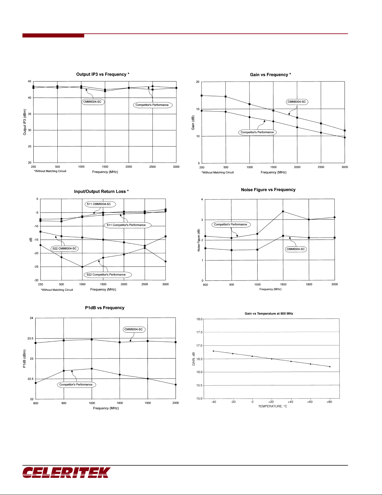
Typical Performance
3236 Scott Boulevard Santa Clara, California 95054 Phone: (408) 986-5060 Fax: (408) 986-5095
CMM6004-SC
Advanced Product Information - April 2003 (3 of 7)
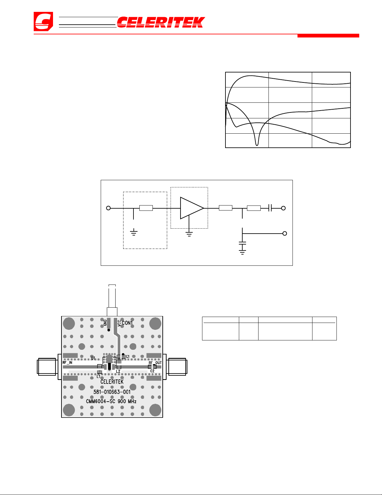
Application Circuit – 900 MHz
(CMM60004-SC-00A0)
Typical Performance (50 Ohm System)
Frequency 900 MHz
Gain 16.5 dB
Input Return Loss -18.0 dB
Output Return Loss -14.0 dB
OIP3 41.0 dBm
Noise Figure 1.8 dB
Bias Vds = 5V, Id = 173 mA
P1dB 23.8 dBm
uuuu
L1
12 nH
RF
IN
CMM6004-SC
SOT-89
T = 80 mil
INPUT MATCHING
NETWORK
RF
OUT
uuuu
C2
56 pF
L2
47 nH
Vcc
5V
C1
56 pF
T = 70 mil
T = 500 mil
Ref Designator Value Description Size
C1, C2 56 pF MCH185A560JK 0603
L1 12 nH TOKO LL1608-F12NK 0603
L2 47 nH TOKO LL1608-F47NK 0603
S-Parameters vs Frequency
20
10
0
-10
-20
-30
0.1 1.1 2.1 3.0
Frequency, GHz
Magnitude, dB
S21
S11
S22
 Loading...