

CELER CMM6004-AH Datasheet
3236 Scott Boulevard Santa Clara, California 95054 Phone: (408) 986-5060 Fax: (408) 986-5095
CMM6004-AH
Features
❏ 0.25 to 6.0 GHz Frequency Range
❏ 41 dBm Output IP3
❏ 1.7 dB Noise Figure
❏ 18.5 dB Gain
❏ 23 dBm P1dB
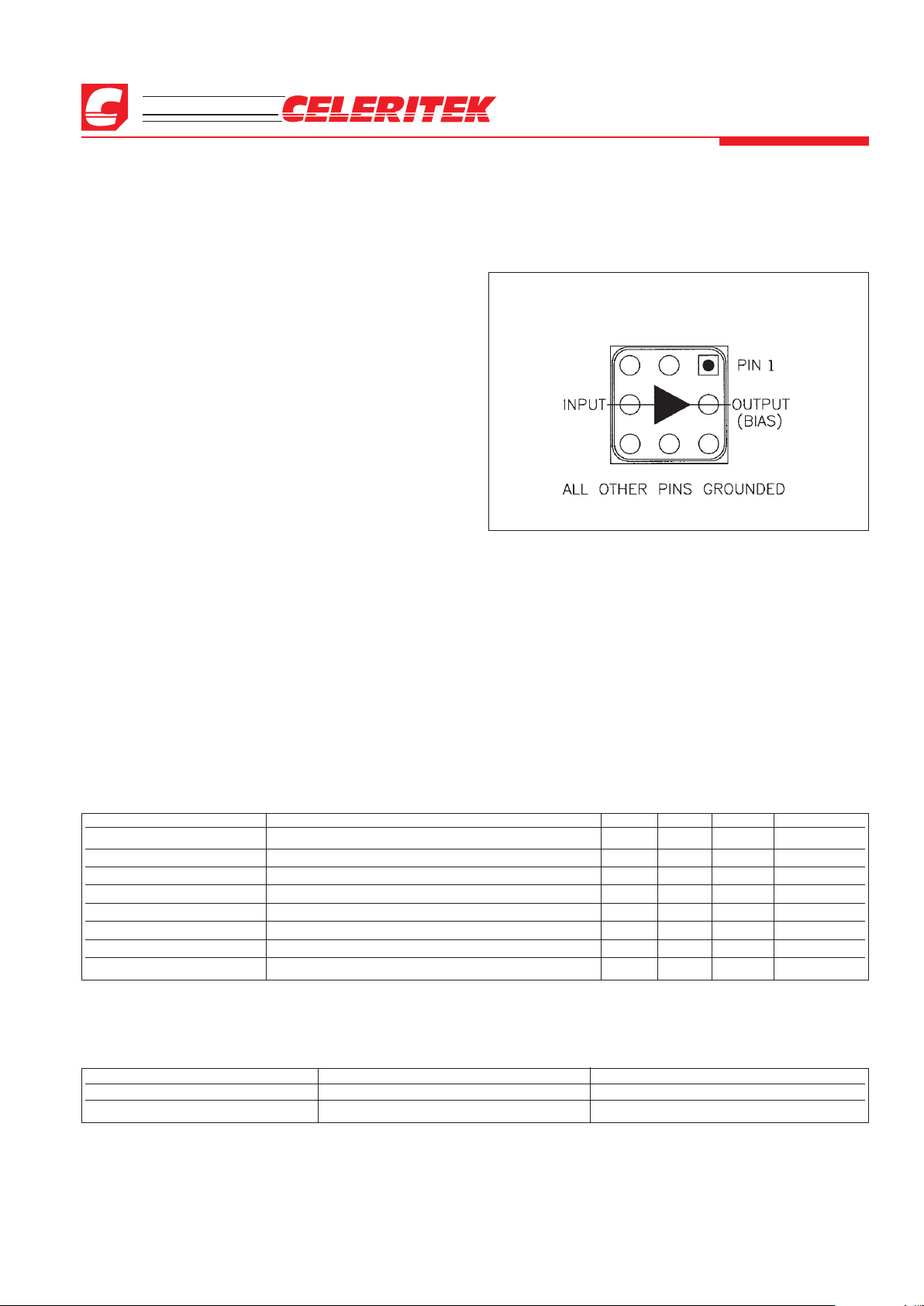
❏ LGA Package
❏ Single Power Supply
❏ Single Input Matching
Applications
❏ Wireless Local Loop Transmit and Receive
❏ UNII Transmit and Receive
❏ Dual Band 802.11 WLAN
Description
The CMM6004-AH is a high dynamic range amplifier designed for applications operating within the 0.25 to 6.0
GHz frequency range. It is an ideal solution for numerous
transmit and receive functions in wireless local loop (WLL)
and UNII applications where high linearity is required.
The amplifier has the flexibility of being optimized
for a number of wireless applications. It is an ideal solution
when used as a driver amplifier in applications including cellular and PCS (personal communications service) operating
from 0.8 to 2.2 GHz; MMDS (multichannel multipoint distrib-
ution systems) operating from 2.2 to 2.7 GHz; WLAN (wireless LAN) operating at 2.4 GHz; WLL (wireless local loop)
operating at 3.5 GHz; and HiperLAN (high performance
LAN) and U-NII (unlicensed national information infrastructure) operating from 5.0 to 6.0 GHz.
The CMM6004-AH is packaged in a low-cost, space
efficient, Land Grid Array (LGA) package which provides
excellent electrical stability and low thermal resistance. All
devices are 100% RF and DC tested. With single input matching the part simplifies design by keeping board space and cost
to a minimum.
0.25 to 6.0 GHz
High Dynamic Range
Amplifier
Advanced Product Information
February 2002 (1 of 6)
Functional Block Diagram
Absolute Maximum Ratings
Parameter Rating Parameter Rating Parameter Rating
Supply Voltage +6.0 V Storage Temperature -40°C to +125°C Operating Temperature -40°C to +85°C
RF Input Power +13 dBm Junction Temperature 150°C
Parameter Condition Min Typ Max Units
Frequency Range 0.25 6.0 GHz
Gain Externally matched 17.0 18.5 19.5 dB
Input Return Loss Externally matched -24 -10 dB
Output IP3 38 41 45 dBm
Noise Figure 1.5 1.7 1.85 dB
Output P1dB 22.5 23.0 23.5 dBm
Operating Current Range 175 185 200 mA
Supply Voltage 5.0 V
Electrical Characteristics
Unless otherwise specified, the following specifications are guaranteed at room temperature in a Celeritek test fixture.
Notes:
1. T = 22°C, Vdd = 5.0, Frequency = 800 MHz, 50 Ohm system
2. Thermal resistance = 50°C/W.
Operation of this device above any of these parameters may cause damage.
3236 Scott Boulevard, Santa Clara, California 95054
Phone: (408) 986-5060 Fax: (408) 986-5095
CMM6004-AH
Advanced Product Information - February 2002
(2 of 6)
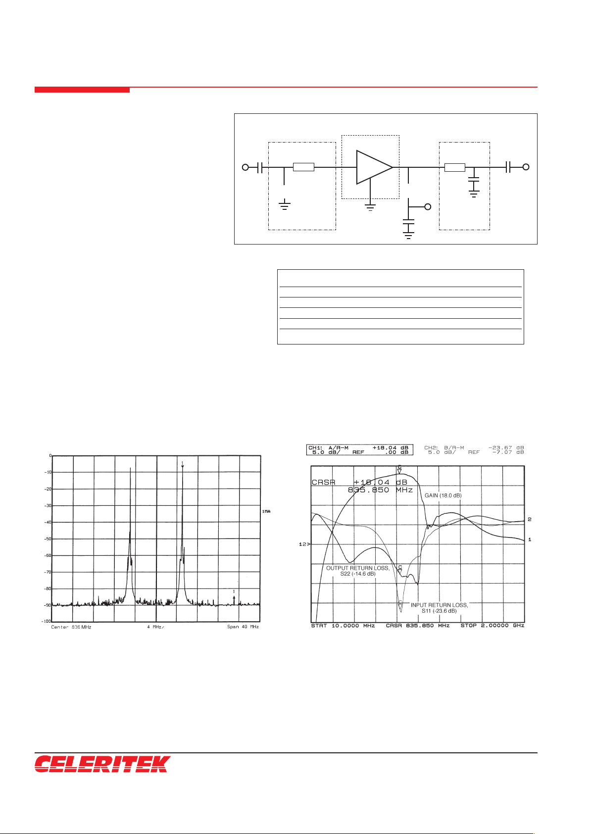
IP3 measured with 2 tones at an output power of 5
dBm/tone separated by 10 MHz
Gain, Input Return Loss and Output Return Loss
vs Frequency
Application Circuit (836 MHz)
Typical Performance (50 Ohm System)
Frequency 836 MHz
Gain 18 dB
Input Return Loss -23 dB
Output Return Loss -14 dB
OIP3 40 dBm
Noise Figure 1.75 dB
Bias Vds = 5V, Id = 175 mA
Typical Performance
RF
OUT
uuuu
uuuu
C3
4.7 pF
C4
100 pF
L2
22 nH
Vcc
5V
C2
1.0 pF
L1
6.8 nH
RF
IN
836 MHz
CMM6004-AH
T1
50 Ω 20°
T1
50 Ω 30°
OUTPUT
MATCHING
NETWORK
INPUT MATCHING
NETWORK
Circuit Board Parts List
Part Reference
Type Designator Description
Inductor L1 0603, 6.8 nH
Inductor L2 0603, 22 nH
Capacitor C1, C4 SMD 0805 NPO, 100 pF
Capacitor C2 0603, 1 pF
Capacitor C3 SMD 0805, 50V ±0.25 pF 4.7 pF
C1
100 pF
 Loading...