

Page 1

VXT1836
Wireless Video Extender Kit
User Guide
Version 6.55
Copyright © 2012 Celeno Communications™ - All Rights Reserved | www.celeno.com pg. 1
Page 2

“Celeno,” the Celeno logo, the tagline “High Definition Home Networking,” “Switched MIMO”,
“OptimizAir” and “Spatial QoS” are trademarks and/or registered trademarks of Celeno
Communications Ltd. and its subsidiaries or affiliates in the United States and/or other countries. All
other company or product names are the trademarks or registered trademarks of their respective
holders. All rights not expressly granted are reserved.
pg. 2 Copyright © 2012 Celeno Communications™ - All Rights Reserved | www.celeno.com
Page 3

Table of Contents
1
Federal Communication Commission Interference Statement ................................................... 5
Who should use this guide .......................................................................................................... 6
Support Information ..................................................................................................................... 6
2
Introduction .......................................................................................................................................... 7
3
Knowing your VXT1836 Kit ............................................................................................................... 8
Package Contents .......................................................................................................................... 8
Hardware Overview ..................................................................................................................... 8
4
Setting Up your VXT1836 Unit ........................................................................................................ 11
Unit Mode (AP/STA) Setting ..................................................................................................... 12
Powering Up your Devices ........................................................................................................ 12
Pairing your Devices ................................................................................................................... 13
Placing and Connecting your Devices ..................................................................................... 13
Connecting to Your VXT1836 Device ....................................................................................... 14
5
Management - Getting Started ........................................................................................................ 16
Logging into the VXT1836 Management Application ........................................................... 16
Navigating the VXT1836 Management Application .............................................................. 17
6
Managing the VXT1836 Device ....................................................................................................... 19
Configuring the VXT1836 Device ............................................................................................. 20
Defining Network Settings ................................................................................................... 20
Defining Wireless Settings .................................................................................................... 22
Defining Security Settings (Access Point Mode Only) ..................................................... 28
Defining WPS Settings .......................................................................................................... 32
Site Survey (Client Mode Only) ........................................................................................... 36
Stations List (Access Point Mode Only).............................................................................. 38
Copyright © 2012 Celeno Communications™ - All Rights Reserved | www.celeno.com pg. 3
Page 4

Configuring Remote Management ...................................................................................... 39
Performing Administration .................................................................................................. 44
Monitoring the VXT1836 Device ............................................................................................... 48
Viewing System Parameters ................................................................................................. 48
A
Troubleshooting VXT1836 Kit .............................................................................................................. 49
Using Rescue Mode: .............................................................................................................. 51
pg. 4 Copyright © 2012 Celeno Communications™ - All Rights Reserved | www.celeno.com
Page 5

Federal Communication Commission Interference Statement
This equipment has been tested and found to comply with the limits for a Class B digital device,
pursuant to Part 15 of the FCC Rules. These limits are designed to provide reasonable protection
against harmful interference in a residential installation. This equipment generates, uses and can
radiate radio frequency energy and, if not installed and used in accordance with the instructions, may
cause harmful interference to radio communications. However, there is no guarantee that interference
will not occur in a particular installation. If this equipment does cause harmful interference to radio or
television reception, which can be determined by turning the equipment off and on, the user is
encouraged to try to correct the interference by one of the following measures:
• Reorient or relocate the receiving antenna.
• Increase the separation between the equipment and receiver.
• Connect the equipment into an outlet on a circuit different from that to which the receiver is
connected.
• Consult the dealer or an experienced radio/TV technician for help.
FCC Caution: Any changes or modifications not expressly approved by the party responsible for
compliance could void the user’s authority to operate this equipment.
This device complies with Part 15 of the FCC Rules. Operation is subject to the following two
conditions: (1) This device may not cause harmful interference, and (2) this device must accept any
interference received, including interference that may cause undesired operation.
This device is going to be operated in 5.15~5.25GHz frequency range, it is restricted in indoor
environment only.
This device and its antenna(s) must not be co-located or operation in conjunction with any other
antenna or transmitter.
IMPORTANT NOTE:
FCC Radiation Exposure Statement:
This equipment complies with FCC radiation exposure limits set forth for an uncontrolled
environment. This equipment should be installed and operated with minimum distance 20cm between
the radiator & your body.
Copyright © 2012 Celeno Communications™ - All Rights Reserved | www.celeno.com pg. 5
Page 6

Preface
Welcome to the VXT1836 Wireless Video Extender solution from Celeno Communications.
The User’s Guide will help you to understand the Wireless Video Extender (VXT) solution,
how to install it, configure it and troubleshoot problems.
Who should use this guide
This User’s Guide assumes that the reader has basic to intermediate computer and internet
skills. All the basic computer networking, Internet, and other information required to
configure the home network and the devices is provided herein.
Support Information
For support inquiries, please contact our field application engineers at
.
pg. 6 Copyright © 2012 Celeno Communications™ - All Rights Reserved | www.celeno.com
Page 7

Introduction
Celeno provides high performance Wi-Fi chips and software for HD home networking
applications.
Celeno’s OptimizAirTM breakthrough technology enables service providers and consumers
to quickly and simply deploy wireless home networks that can securely deliver multiple
streams of carrier-quality SDTV and HDTV, and any other multimedia content throughout
the home. The Celeno solution is optimized toward Quality of Experience (QoE) and
performance consistency in both capacity and coverage.
The Wireless Video Extender (VXT) 1836 solution is a “Celeno-Powered” multi-function
unit – that can be set as an “Access Point” or as a “Station” device. Building a Wireless
Video network requires two or more VXT1836 units communicating with each other enabling distribution of high-definition video streams from one central location to a TV set
in the house without replacing existing routers, gateways, set-top boxes or laying out new
cables across the house.
1
Your Wireless Video Extender unit may be used as a:
• Wireless Video Extender Access Point (AP) ()
i.e. connected to home gateway or cable/DSL modem
• Wireless Video Extender Station (STA) ()
i.e. connected to set-top box or media storage/player
Please Note:
A minimum of two units are required to establish a wireless video extender network
• One unit should be configured as an Access Point
• One or more units configured as Stations can be associated with the wireless video
extender AP
Copyright © 2012 Celeno Communications™ - All Rights Reserved | www.celeno.com pg. 7
Page 8

Knowing your VXT1836 Kit
Package Contents
Your VXT1836 Kit contains the following items:
1. One VXT1836 wireless video extender unit
2. One CAT5 cable
2
3. One power transformer for the VXT1836 device
4. One “Quick Installation Guide”
Note: You would need at least two VXT1836 kits to establish a network
Hardware Overview
The VXT1836 unit is a dual function “Access Point” or “Station” device.
The VXT1836 is powered by Celeno’s CL1800 802.11n WiFi chipset that employs
sophisticated algorithms and techniques, such as Beam Forming, to reliably stream High
Definition video to any location in the home.
The VXT1836 unit set as “Access Point” connects to the video source which can be a
gateway, a cable/DSL modem or a DVR/PVR device.
The VXT1836 unit set as “Station” connects to the video receiving set-top box device.
pg. 8 Copyright © 2012 Celeno Communications™ - All Rights Reserved | www.celeno.com
Page 9
WPS LED
Power
LED
Reset/Restore
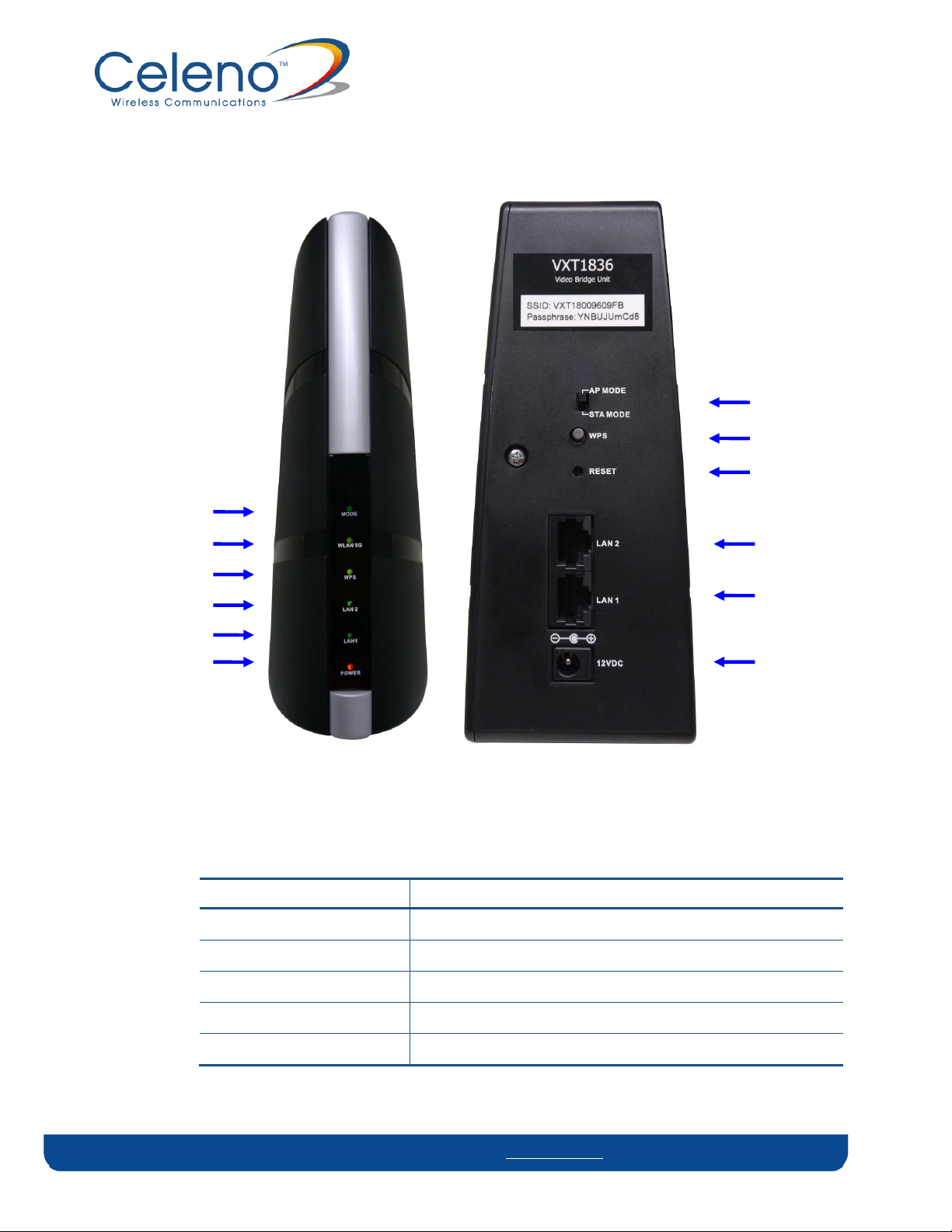
The VXT1836 devices have been designed to be placed on a desktop. All of the cables exit from the rear
of the devices. The status display LEDs are located at the front of the devices and are easily visible.
AP/STA Mode Switch
WPS Button
Defaults Button
AP/STA Mode LED
WLAN LED
LAN2 LED
LAN1 LED
LAN2 Ethernet Interface
LAN1 Ethernet Interface
12VDC Power Interface
Figure 1: VXT1836
The following table describes the connectors on the rear panel of the VXT1836 device:
Table 1: VXT1836 Rear Panel – Connectors and Buttons
Name Description
AP/STA Mode Switch Sets the device functionality as Access Point or Station
WPS Button WPS button for easy unit association in the network
Reset Reset and restore defaults button.
LAN2 / LAN1 2 Ethernet ports, each may be used for Data or Management
Power In DC power input. 12 VDC.
Copyright © 2012 Celeno Communications™ - All Rights Reserved | www.celeno.com pg. 9
Page 10

The following table describes the LED indications on the front panel of the VXT1836 Device.
Table 2 - VXT1836 LEDs
Name Color Description
Power
Green The device is powered on.
Red The device has entered a power save mode.
Off The device is powered off.
AP/STA Mode
LAN1 / LAN2
WPS
WLAN 5G
Blue The device is running as Access Point (AP)
Green The device is running as Station (STA)
Green The LAN port is connected to a network device.
Off The LAN port is either not connected or there is
no activity on the link.
Green WPS pairing was successfully completed. This is a
temporary state that lasts for 2 minutes.
Flashing Green WPS pairing is in progress. This is a temporary
state that lasts for 2 minutes or until WPS pairing
succeeds.
Off Default.
Green
Flashing Green
Access Point Behavior - At least one Station is
associated with the Access Point.
Station Behavior – The Station is associated with
an Access Point and can receive at least one high
definition video stream.
Station Behavior – The Station is associated with
an Access Point but does not have enough
capacity to receive constantly high definition
video streams.
Off
Access Point Behavior - No Stations are
associated with the Access Point.
Station Behavior – The Station is not associated
with an Access Point.
Note: The Mode LED indicates the current active mode. To change the mode a unit power
cycle is required. Following the power cycle the mode LED will reflect the change.
pg. 10 Copyright © 2012 Celeno Communications™ - All Rights Reserved | www.celeno.com
Page 11

The following LED combinations describe special indications:
Combination –The WLAN, LAN and WPS LEDs are flashing simultaneously for 10
seconds.
Description – The device is undergoing a “Restore Defaults” procedure.
Combination –The WLAN, LAN and WPS LEDs are flashing in sequence for 10 seconds.
Description – The device is undergoing a “Software Upgrade” procedure.
Combination –WLAN LED is flashing
Description – The AP device is currently performing a Channel Activity Check (CAC)
process.
Setting Up your VXT1836 Unit
Setting up the system involves the following steps:
Unit mode (AP/STA) device setting
Powering up your device
Pairing your device
Placing and connecting your device
After performing these steps, you can start streaming High Definition video through the
VXT1836 Kit.
Changing your computer’s IP address
After performing this additional step, you can use the VXT1836 Management Application
to configure and manage your VXT1836 device. (Refer to Managing the VXT1836 Device on
page 19).
Copyright © 2012 Celeno Communications™ - All Rights Reserved | www.celeno.com pg. 11
Page 12
Unit Mode (AP/STA) Setting
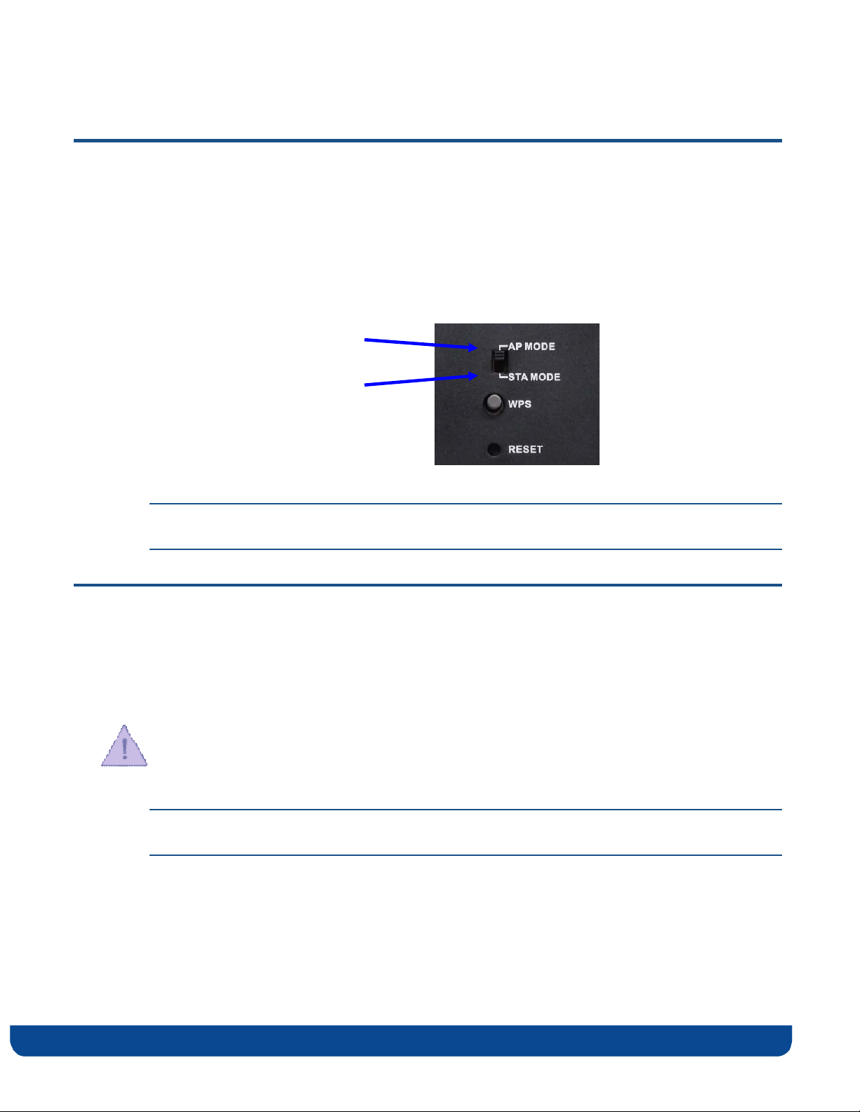
To set/modify the VXT1836 device operating mode:
1. Make sure the unit is UNPLUGGED from the 12V A/C adapter – check that all LEDs
are off.
2. Change the AP/STA Mode switch at the back of the unit to the desired mode:
Switch on top position
for “AP” (Access Point) mode
Switch on bottom position
for “STA” (Station) mode
Note: Only a single VXT1836 unit should be set as an AP in the network, the remaining
units should be set as STAs.
Powering Up your Devices
To power up the VXT1836 device:
3. Plug in the 12V A/C adapter and connect it to the VXT1836 device.
Use the recommended AC/DC power adaptor which was supplied in the kit.
Using a power supply with a different voltage rating then the one included with the
VXT1836 device will cause damage and void the warranty for this product.
Note: There is no On/Off switch. Once you connect the power adapter, the VXT1836
device powers up.
4. Wait several seconds while the VXT1836 device performs a reset.
pg. 12 Copyright © 2012 Celeno Communications™ - All Rights Reserved | www.celeno.com
Page 13

Pairing your Devices
To pair the VXT1836 Access Point and VXT1836 Station devices:
1. Place the VXT1836 set as Access Point and the VXT1836 set as Station devices between 1
to 3 meters from each other.
2. Pair the devices by pressing the WPS button on the back panel of each device. You can
release the button as soon as the WPS LED begins flashing.
Note: The WPS buttons of both devices (Access Point and Station) should be pressed
within 2 minutes period. The buttons can be pressed in any order.
3. Wait for the pairing process to complete by watching the LEDs on the devices:
While pairing is in progress the WPS LED is flashing
After successful pairing the WPS LED stays on for 2 minutes.
Placing and Connecting your Devices
To place and connect your VXT1836 set as Access Point device:
1. Place the VXT1836 set as Access Point device on an easily accessible surface near the
home gateway, Cable/DSL Modem or DVR/PVR device.
2. Plug one end of the Ethernet cable into the LAN port of the gateway device and the
other end into one of the Ethernet ports of the VXT1836 Access Point (LAN1 or LAN2).
To place and connect your VXT1836 set as Station device:
1. Place the VXT1836 set as Station device on an easily accessible surface near the set-top
box.
2. Plug one end of the Ethernet cable into the LAN port of the set-top box device and the
other end into one of the Ethernet ports of the VXT1836 (LAN1 or LAN2).
Note: Two network devices can be simultaneously connected to the VXT1836 unit e.g. a
set-top box and a network media storage or media player.
3. Make sure that the WLAN 5G LED is solid green
Copyright © 2012 Celeno Communications™ - All Rights Reserved | www.celeno.com pg. 13
Page 14

If the WLAN LED is turned off, or flashing (on the Station device), try to reposition the
device to a more elevated location and as far as possible from large metallic objects.
Completing the installation:
You have finished installing your VXT1836 device. To test your connectivity, turn on the
TV and set-top box and watch any available channel.
Note: To install additional VXT1836 Station devices, repeat the above procedure for each
new VXT1836 Station device.
Connecting to Your VXT1836 Device
The VXT1836 operating as an Access Point is pre-configured with the following IP
parameters:
• IP Address: 10.0.0.2
• Net Mask: 255.0.0.0
The VXT1836 operating as a Station is pre-configured with the following IP parameters:
• IP Address: 10.0.0.10
• Net Mask: 255.0.0.0
In order to connect your management computer to the VXT1836 device, connect the
VXT1836 device directly to your computer and change the IP address of your computer so
that it is on the same subnet as the VXT1836 device (by default 10.x.x.x). Since this
disconnects your computer from your computer network, you may need to restore this
setting later.
To change the IP address of your computer:
1. Connect an Ethernet cable between one of the Ethernet ports of the VXT1836 device and
the Ethernet port of your computer.
2. On Windows XP:
i. From your computer’s desktop, click Start > Settings > Network Connections
and double-click the LAN connection for your computer network. The Local
Area Connection Status window appears.
pg. 14 Copyright © 2012 Celeno Communications™ - All Rights Reserved | www.celeno.com
Page 15
ii. From the General tab, click Properties. The Local Area Connection Properties
window appears.
3. On Windows 7:
i. From your computer’s desktop, click Start>Control Panel, click on Network and
Sharing Center
ii. Select Change Adaptor Settings, and following right click on Local Area Connection
and click on Properties. The Local Connection Area Properties Window appears.
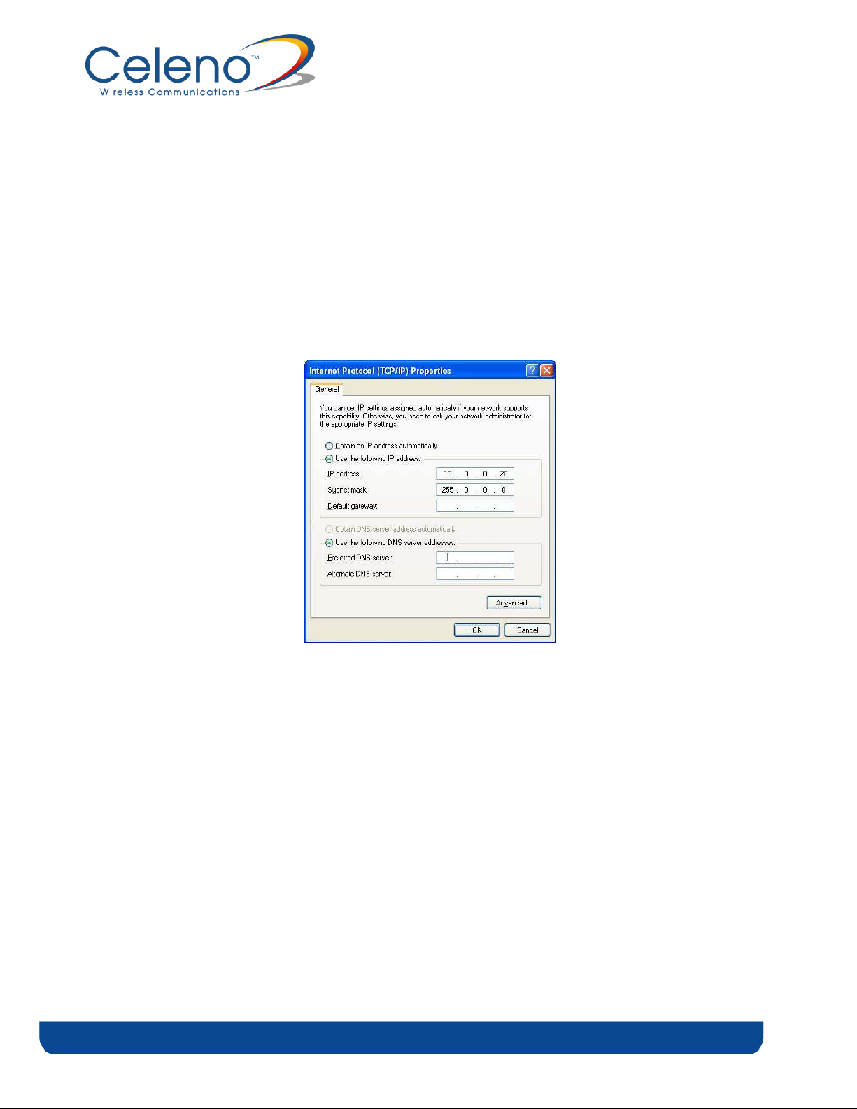
4. Select Internet Protocol (TCP/IP) and click Properties. The Internet Protocol (TCP/IP)
Properties window appears.
Figure 2: Internet Protocol (TCP/IP) Properties Window
5. Make a note of the current settings in this window. You will need to know these
settings when reconnecting your computer to your computer network.
6. Check Use the following IP address and type an IP address in the same subnet as the
VXT1836, in the following format: 10.x.x.x. Be sure to use an IP address that is different
from the IP address of your VXT1836 device which is either 10.0.0.2 or 10.0.0.10 by
default.
7. Click OK to save the information and close the Internet Protocol (TCP/IP) Properties
window.
8. Click OK to close the Local Area Connection Properties window.
9. Click Close to close the Local Area Connection Status window
Copyright © 2012 Celeno Communications™ - All Rights Reserved | www.celeno.com pg. 15
Page 16
Management - Getting Started
The VXT1836 Management Application is a web-based tool that enables you to manage
and configure your VXT1836 device. This chapter describes how to navigate through the
VXT1836 Management Application:
Note: Ensure that you have connected an Ethernet cable between your computer and the
VXT1836 device.
3
Logging into the VXT1836 Management Application
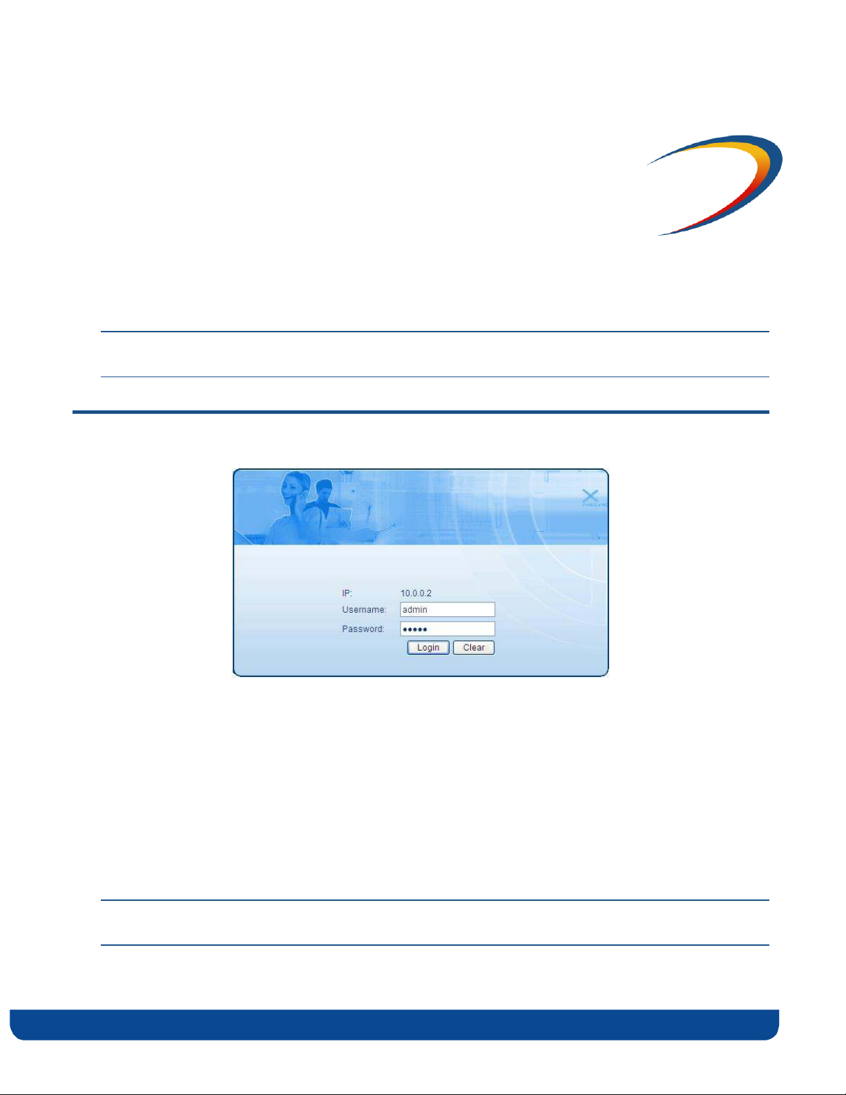
Figure 3 - VXT1836 Management Application – Login Screen
The VXT1836 Management Application is password protected. To access its functions you
first need to successfully log in:
1. Type the username and password into the appropriate fields and click on the Login
button.
2. On successful login you will be forwarded to a VXT1836 Management Application
configuration screen.
Note: The default username and password are admin, admin respectively. To change these values
refer to Performing Administration on page 44.
pg. 16 Copyright © 2012 Celeno Communications™ - All Rights Reserved | www.celeno.com
Page 17
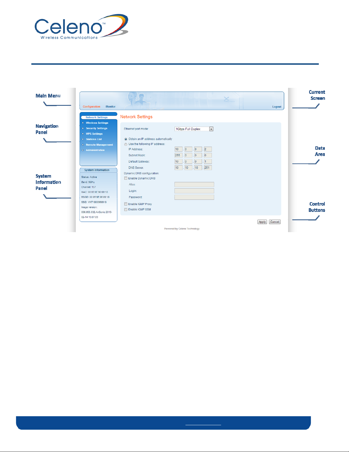
Navigating the VXT1836 Management Application
Figure 4: VXT1836 Management Application Window
The VXT1836 Management Application contains the following controls and areas to help
you navigate to all its parameters.
Main Menu – Enables you to access the functions of the VXT1836 Management
Application. The Main Menu is divided into the following submenu items:
Configuration, Monitor and Logout.
Navigation Panel – Displays the configuration screens available for each submenu item.
Current Screen – Displays the name of the current configuration screen.
System Information Panel – Displays system status information. This panel is always
visible and displays the following information:
Status – Indicates whether the system is currently active or inactive.
Band – Indicates that the system is currently transmitting in the 5 GHz radio band.
Copyright © 2012 Celeno Communications™ - All Rights Reserved | www.celeno.com pg. 17
Page 18

Channel – The index number of the channel currently in use.
MAC – The local MAC Address of the device.
BSSID – Basic Service Set Identifier. This field uniquely identifies each BSS. You
cannot configure this parameter using the VXT1836 Management Application.
SSID – Service Set Identifier. The code attached to beacon frames and connection
establishment frames.
Image Version – The current software image version of the device.
Data Area – For each configuration screen, the Data Area displays the relevant
parameters and controls.
Control Buttons – Enable you to perform operations related to the current
configuration screen.
Note: You can logout of the application anytime by selecting the Logout menu item at the upper
right corner of the screen.
Note: The VXT1836 device can be set as an Access Point or as a Station (using the external
AP/STA mode switch). Each mode of operation has different configuration screens.
pg. 18 Copyright © 2012 Celeno Communications™ - All Rights Reserved | www.celeno.com
Page 19

Managing the VXT1836 Device
The VXT1836 Management Application is a user-friendly application that enables you to
configure and control all the parameters of the VXT1836. The main menu contains the
following options:
Configuration
Monitor
Note: Clicking Cancel in any of the VXT1836 Management Application windows discards any
unsaved changes you have made. The VXT1836 Management Application then re-queries
the VXT1836 device and refreshes the display.
4
True HD Home Networking. Unwired.™
Page 20
Configuring the VXT1836 Device
Defining Network Settings
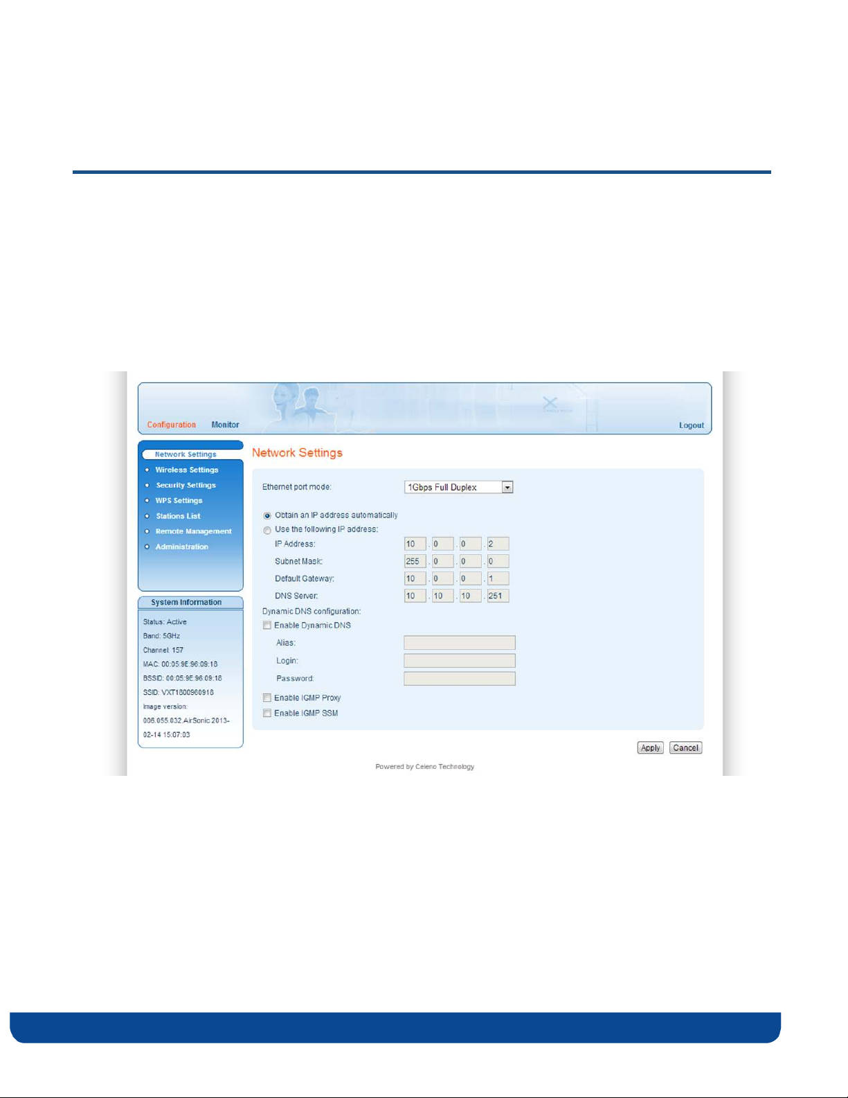
To define network settings:
1. From the main menu of the VXT1836 Management Application, click Configuration.
Then click Network Settings on the navigation panel. The Configuration, Network
Settings window appears.
Figure 5: VXT1836 Management Application – Configuration, Network Settings Window
pg. 20 Copyright © 2012 Celeno Communications™ - All Rights Reserved | www.celeno.com
Page 21

The following table describes the parameters you can configure from this window:
Table 3: VXT1836 Configuration – Network Parameters
Parameter Description
Ethernet port mode The properties of the Ethernet (LAN) port of the
device: Can be either auto negotiated up to 1Gbps
or fixed to 100Mbps.
Obtain an IP address automatically When selected, the device acts as a DHCP client
and obtains its IP properties automatically.
IP Address The IP address of the VXT1836 device
(under static IP setting)
Subnet Mask The subnet mask of the VXT1836 device.
(under static IP setting)
Default Gateway The default gateway of the VXT1836 device.
(under static IP setting)
DNS Server The DNS server of the VXT1836 device.
(under static IP setting)
Enable Dynamic DNS When checked the VXT1836 device will use
dynamic DNS protocol to register its alias into the
DNS server. This will allow accessing the device
using the given alias instead of its IP address.
Alias The given hostname of the VXT1836 device
Login and Password The login credentials of the DNS server/home
router.
Enable IGMP Proxy* The device will operate as an IGMP Proxy
Enable IGMP SSM* The device will support IGMP SSM
2. Click Apply to update the settings immediately. The system displays an update
message.
3. Click OK and wait for the system to restart.
* AP only parameter
Copyright © 2012 Celeno Communications™ - All Rights Reserved | www.celeno.com pg. 21
Page 22
Defining Wireless Settings
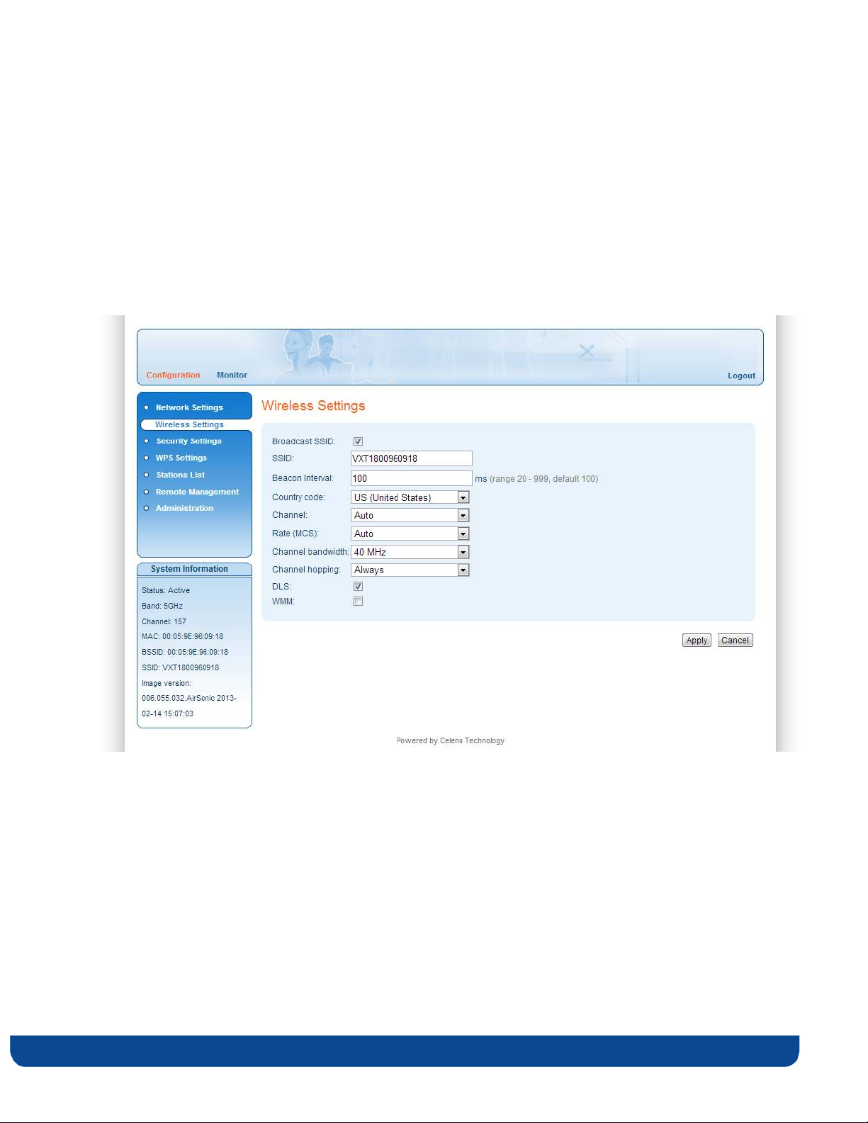
To define wireless settings in Access Point mode:
1. From the main menu of the VXT1836 Management Application, click Configuration
and from the Navigation Panel, click Wireless Settings. The Configuration, Wireless
Settings window appears.
Figure 6: VXT1836 Management Application – Configuration, Wireless Settings Window (AP)
The following table describes the parameters you can configure from this window:
pg. 22 Copyright © 2012 Celeno Communications™ - All Rights Reserved | www.celeno.com
Page 23

Table 4: VXT1836 Configuration – Wireless Parameters (AP)
Parameter Description
Broadcast SSID When checked, the system broadcast its SSID in beacon and probe
response frames.
SSID Service set identifier. The code attached to beacon frames and connection
establishment frames. The SSID is a string of ASCII characters.
Beacon Interval The time interval between beacon frames sent out by the system.
Possible values: 20 – 999 milliseconds.
Country code Your country of operation.
This device will automatically limit the allowable channels
determined by the current country of operation. Incorrectly entering the
country of operation may result in illegal operation and may cause
harmful interference to other systems.
Frequency
(Channel)
Rate The transmission rate (MCS). Possible values: 0-15, and Auto.
Channel
bandwidth
Channel hopping Determines the system behavior when interference is detected:
DLS When checked the system employs the direct link protocol to enable
Select the desired channel from the dropdown list, or let the system
select the best working channel automatically by choosing ‘Auto’ from
the drop down list.
Selecting auto lets the system dynamically adapt the transmission rate to
suit current network conditions.
The bandwidth that system occupies: 20MHz / 40MHz.
Always – Change channel as soon as interference is detected on the
current radio channel.
Conditional – Change channel as soon as interference is detected only if
no video is being streamed through the system.
direct client to client communication. Use this option when client devices
in your network can stream video to each other, such as in a Multi-Room
DVR deployment.
Copyright © 2012 Celeno Communications™ - All Rights Reserved | www.celeno.com pg. 23
Page 24

Parameter Description
WMM When checked the system performs traffic classification and
prioritization according to the WI-FI Multimedia interoperability
certification program. This will ensure that your voice and video streams
will not be impaired by other types of traffic.
Use this option only if you are certain that the voice and video
streams that enter the system are marked with DSCP to indicate their
priority.
2. Click Apply to update the settings immediately. The system displays an update
message.
3. Click OK and wait for the system to restart.
pg. 24 Copyright © 2012 Celeno Communications™ - All Rights Reserved | www.celeno.com
Page 25

Understanding Quality of Service in VXT1836
VXT1836 implements Quality of Service in the downlink direction (AP to stations).
Enabling Quality of Service is done by checking the WMM checkbox in the Wireless
Setting configuration menu.
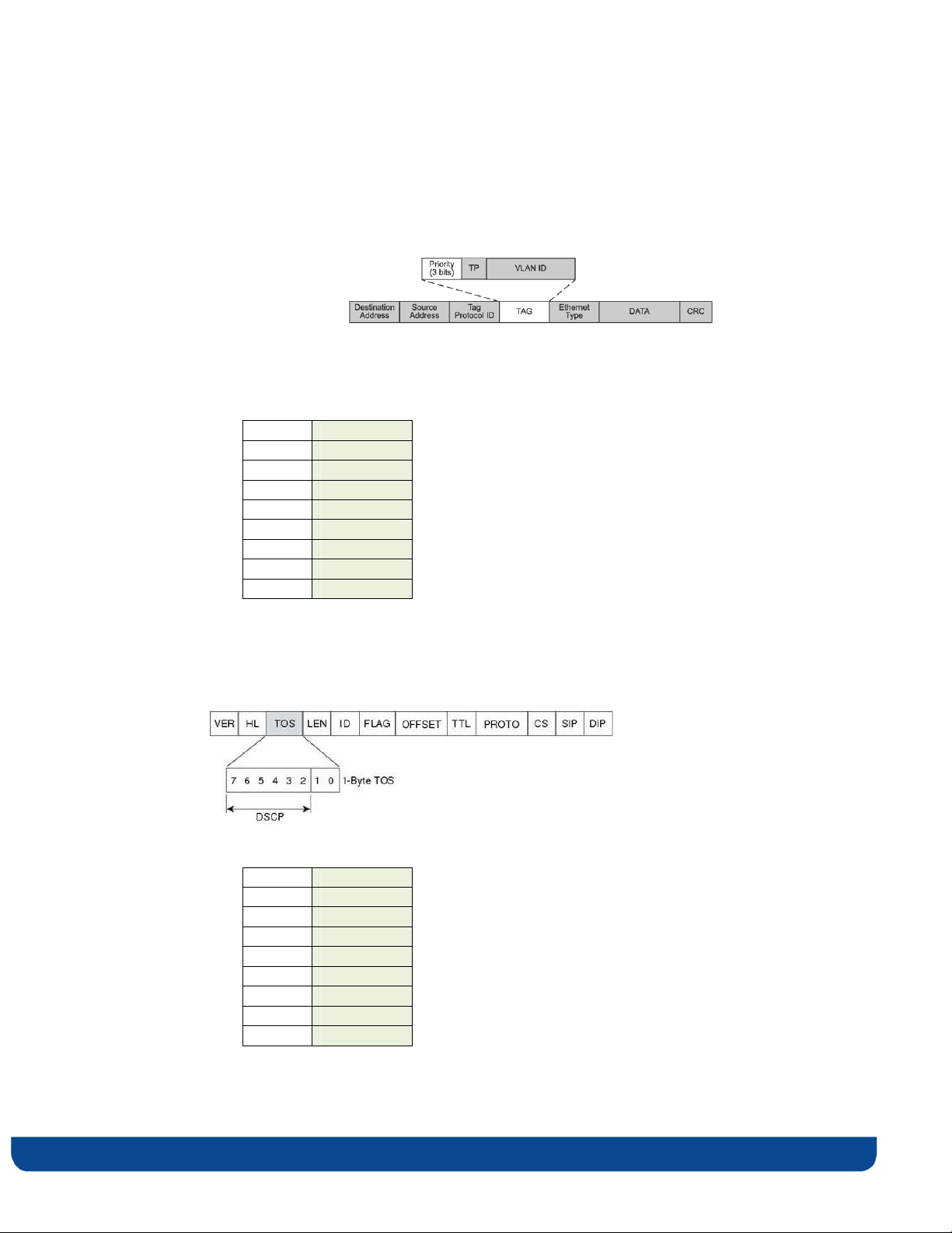
1. Once enabled, the traffic classification is implemented according to the following
rule:
• If the data is VLAN tagged, classification is based on VLAN PRIORITY
(Layer2)
• If the data is untagged, classification is based on DSCP (Layer 3)
2. The incoming data from the Ethernet port is mapped to the proper wireless
access category according to the classification rules explained below.
3. The transmission air scheduling is than performed according to the following
order:
a. VoIP Access Category of managed devices (VXT1836 clients)
b. VoIP Access Category of unmanaged devices
c. Video Access Category of managed devices
d. Video Access Category of unmanaged devices
e. Rest of data (Data, and Background) first of managed followed by
unmanaged
Copyright © 2012 Celeno Communications™ - All Rights Reserved | www.celeno.com pg. 25
Page 26
VLAN based Classification
Once the data received for transmission is tagged, classification is based on the 802.1p
priority:
In such cases, mapping of the 802.1p priority bit to User Priority is according to the
following:
802.1p User Priority
7 0
5, 6 1
2
4 3
3 4
1 5
2 6
0 7
DSCP based Classification
In case the data received for transmission is untagged, classification is based on DSCP
which is part of the TOS Byte:
In such cases, the mapping of the DSCP to User Priority is accoring to the following:
DSCP User Priority
0 0
8 1
16 2
24 3
32 4
40 5
48 6
56 7
pg. 26 Copyright © 2012 Celeno Communications™ - All Rights Reserved | www.celeno.com
Page 27
User Priority is in-turn mapped to Wi-Fi Multimedia (WMM) Access Category aligned
with the Wi-Fi Alliance recommendation as listed below:
User
Priority
0 BE Best Effort
1 BK Background
2 BK Background
3 BE Best Effort
4 VI Video
5 VI Video
6 VO Voice
7 VO Voice
WMM Access
Category
Traffic Type
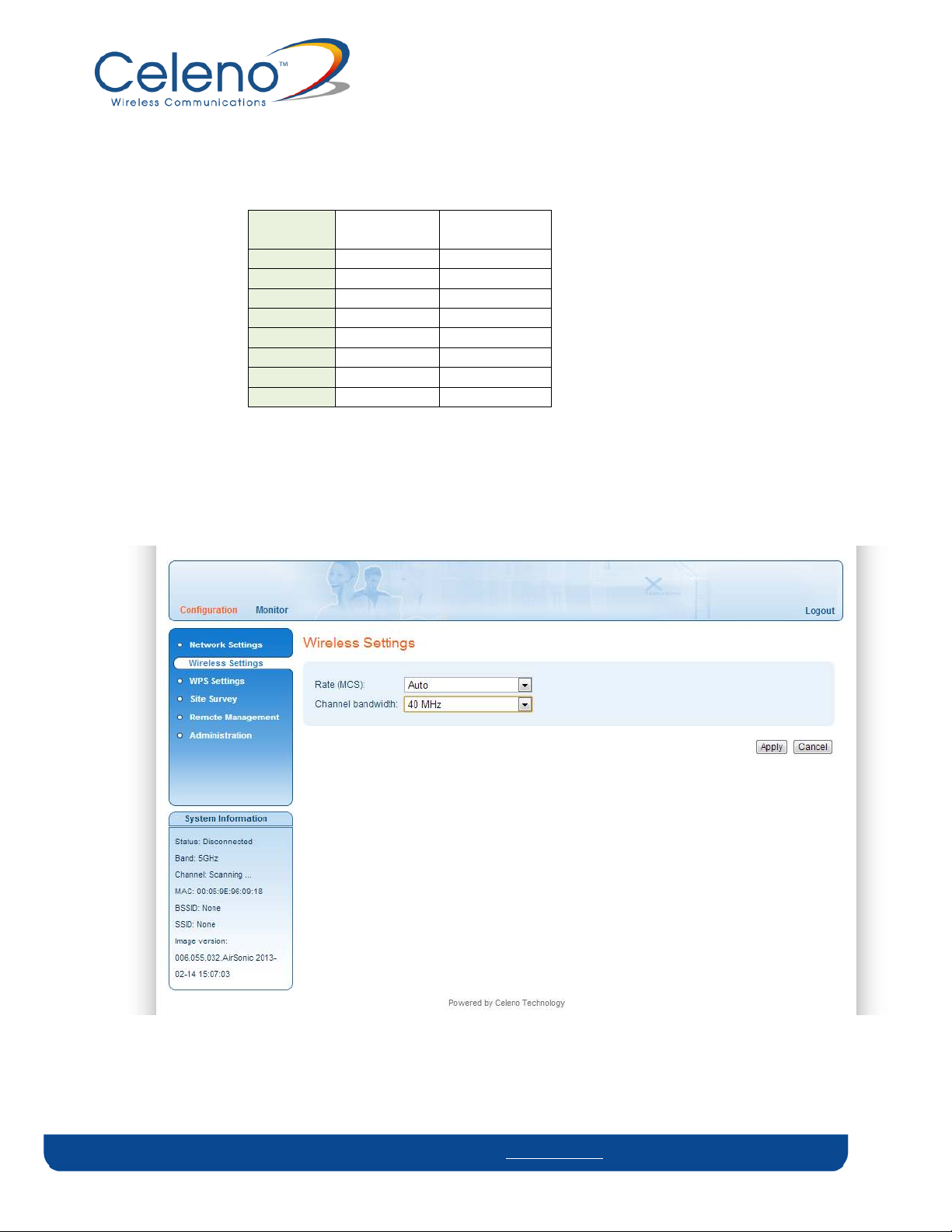
To define wireless settings in Client mode:
1. From the main menu of the VXT1836 Management Application, click Configuration
and from the Navigation Panel, click Wireless Settings. The Configuration, Wireless
Settings window appears.
Figure 7: VXT1836 Management Application – Configuration, Wireless Settings Window (STA)
Copyright © 2012 Celeno Communications™ - All Rights Reserved | www.celeno.com pg. 27
Page 28

The following table describes the parameters you can configure from this window:
Table 5: VXT1836 Configuration – Wireless Parameters (STA)
Parameter Description
Rate The transmission rate (MCS). Possible values: 0-15, and Auto.
Selecting auto lets the system dynamically adapt the transmission rate to
suit current network conditions.
Channel
bandwidth
2. Click Apply to update the settings immediately. The system displays an update
message.
3. Click OK and wait for the system to restart.
The bandwidth that system occupies.
Defining Security Settings (Access Point Mode Only)
To define Security settings:
1. From the main menu of the VXT1836 Management Application, click Configuration
and from the Navigation Panel, click Security Settings. The Configuration, Security
Settings window appears.
The VXT1836 device can be configured to operate in one of the following security modes:
Unsecured – Wireless security is disabled, any client can associate to the VXT1836
Access Point and the wireless signal is passed unencrypted.
WEP – Stands for Wireless Equivalent Privacy. It is the legacy 802.11 security standard
and provides only basic security. WEP can be easily cracked and it is recommended to
use WPA2 instead.
WPA2/PSK - Stands for WiFi Protected Access. It is based on the IEEE 802.11i standard
and uses AES/TKIP encryption algorithm. WPA2 is much more secure then WEP, it
provides best in class encryption and user authentication. It is recommended that you
enable WPA2 at all times.
To be able to use Wireless Protected Setup (WPS) features (See at page 32), it is required
that you enable the WPA2/PSK security mode.
pg. 28 Copyright © 2012 Celeno Communications™ - All Rights Reserved | www.celeno.com
Page 29
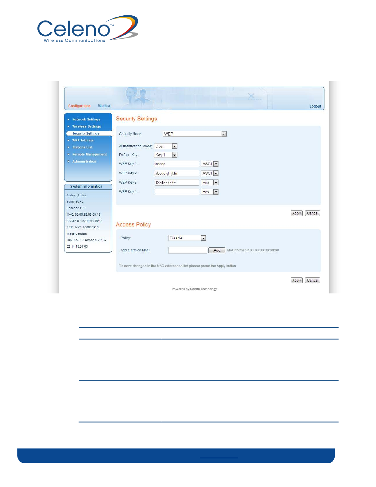
To define WEP settings:
Figure 8 - VXT1836 Management Application – Configuration, Security Settings Window, WEP Mode
Table 6: VXT1836 Configuration – Security Parameters, WEP mode.
Parameter Description
Security Mode The selected security mode. Possible values: Disable, WEP and
WPA2-PSK.
Authentication Mode The selected authentication mode. Possible values are Open
and Shared.
Default Key The index of the encryption key that will be used for
transmissions.
WEP Key 1-4 The WEP encryption keys. Keys can be entered either as
normal alpha-numeric characters or as hexadecimal digits.
Copyright © 2012 Celeno Communications™ - All Rights Reserved | www.celeno.com pg. 29
Page 30
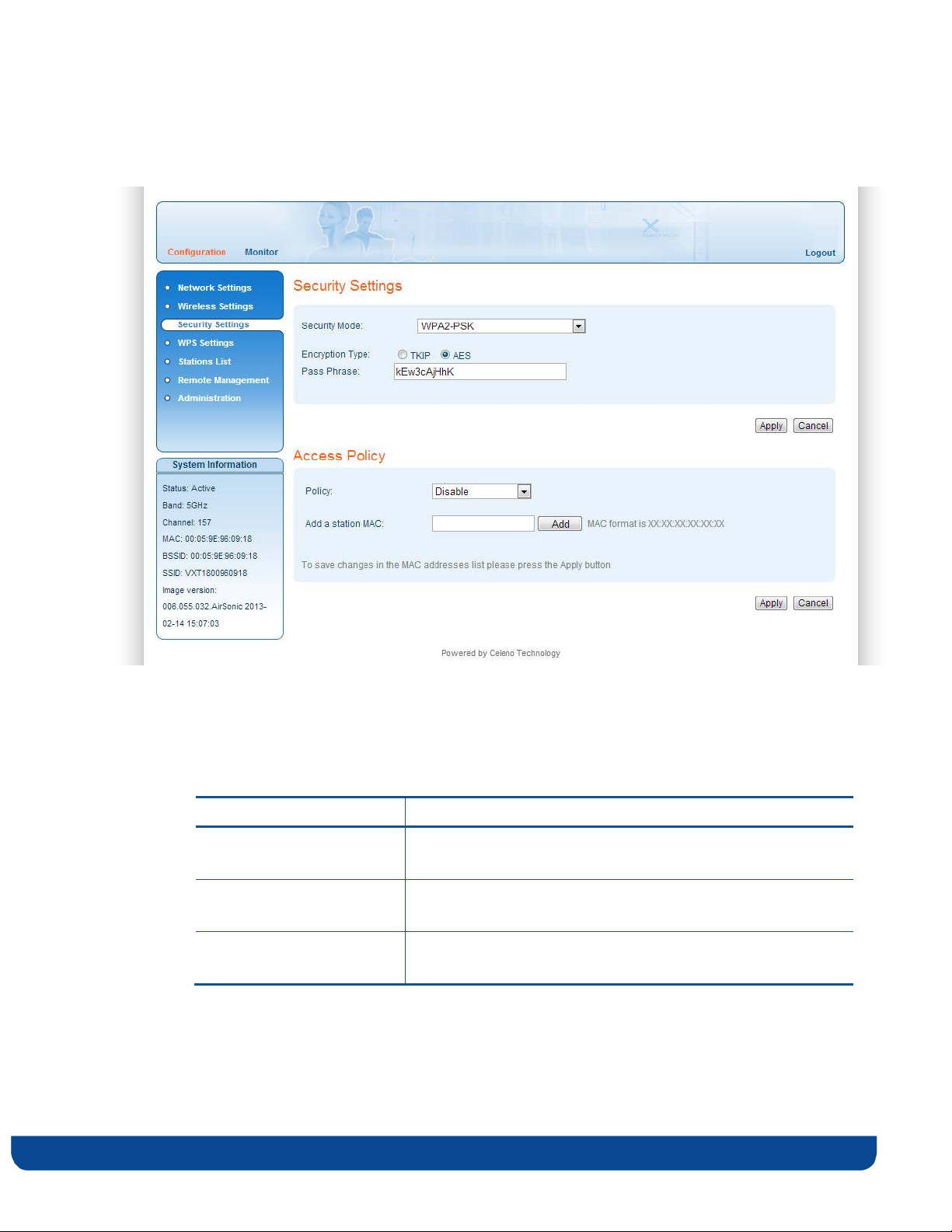
To define WPA2-PSK settings (default):
Figure 9 - VXT1836 Management Application – Configuration, Security Settings Window, WPA2-PSK Mode
Table 7: VXT1836 Configuration – Security Parameters, WPA2-PSK mode.
Parameter Description
Security Mode The selected security mode. Possible values: Disable, WEP and
WPA2-PSK.
WPA Algorithm The selected encryption algorithm. Possible values: AES
(recommended) and TKIP.
Pass Phrase The security pass phrase to be used for generating the WPA2
encryption keys. The pass phrase can be 8 to 63 bytes long.
pg. 30 Copyright © 2012 Celeno Communications™ - All Rights Reserved | www.celeno.com
Page 31

Access Policies:
The VXT1836 device can be configured to control which wireless client devices can
associate with it. The available access policies are:
Disable – Any wireless client device can associate with the VXT1836 Access Point.
Allow – A white list of allowed MAC addresses determines which wireless client
devices are allowed to associate with the VXT1836 Access Point.
Reject – A black list of banned MAC addresses determines which wireless client
devices are not allowed to associate with the VXT1836 Access Point.
Table 8 VXT1836 Configuration – Access Policy Parameters.
Parameter Description
Policy The selected Access Policy. Possible values: Disable Allow and
Reject.
Add a station MAC Enter a MAC address of a wireless client device and press the
Add button to add it to the list of allowed/banned wireless
client devices.
Press the Delete button to remove a wireless client device
from the list.
2. Click Apply to update the settings immediately. The system displays an update
message.
3. Click OK and wait for the system to restart.
Copyright © 2012 Celeno Communications™ - All Rights Reserved | www.celeno.com pg. 31
Page 32
Defining WPS Settings
WPS is a standard for easy and secure setup of wireless home networks, created by the
WiFi Alliance. The VXT1836 Kit implements two WPS pairing methods:
The WPS-PBC configuration method allows you to pair VXT1836 Access Point and client
devices using a push button (See Pairing your Devices on page 13).
The WPS-PIN configuration method allows you to pair VXT1836 Access Point and client
devices by entering the PIN code of the client device in the VXT1836 Access Point WEB UI.
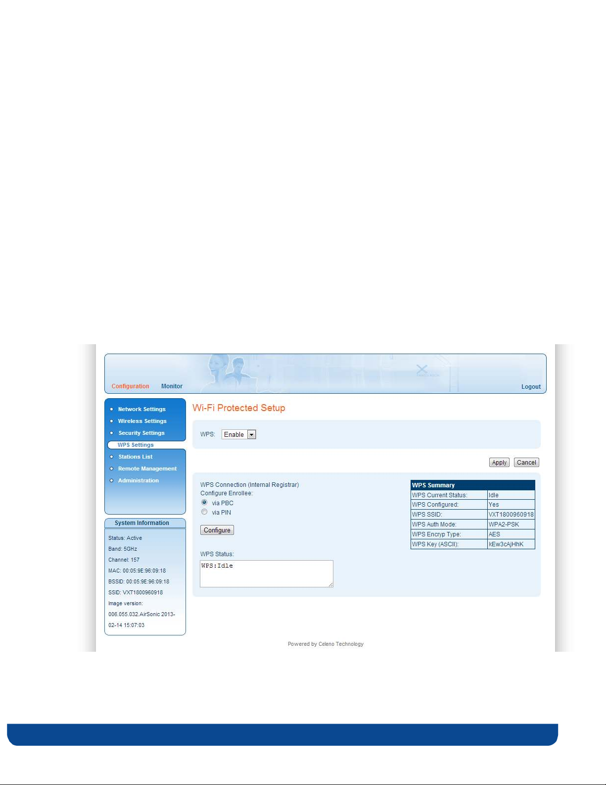
To define WPS settings in Access Point mode:
1. From the main menu of the VXT1836 Management Application, click Configuration
and from the Navigation Panel, click WPS Settings. The Configuration, WPS Settings
window appears.
Figure 11: VXT1836 Management Application – Configuration, WPS Settings Window
pg. 32 Copyright © 2012 Celeno Communications™ - All Rights Reserved | www.celeno.com
Page 33
The following table describes the actions that can be performed from this window:
Table 11: VXT1836 Configuration – WPS Parameters
Parameter Description
WPS Enable / Disable WPS.
WPS Connection The pairing method. Can be either WPS-PBC or WPS-PIN.
PIN The PIN code of the wireless client device (under WPS-PIN)
Configure Initiates a WPS pairing procedure
WPS Status Indicates the status of the WPS pairing procedure
WPS Summary Displays a quick summary of the WPS parameters
2. Click Apply to update the settings offline. The system stores the new settings and
prompts you to restart the system.
3. Click YES and wait for the system to restart.
Note: A WPS-PBC pairing procedure can also be initiated by pressing the WPS button on the
front panel of the device.
Copyright © 2012 Celeno Communications™ - All Rights Reserved | www.celeno.com pg. 33
Page 34
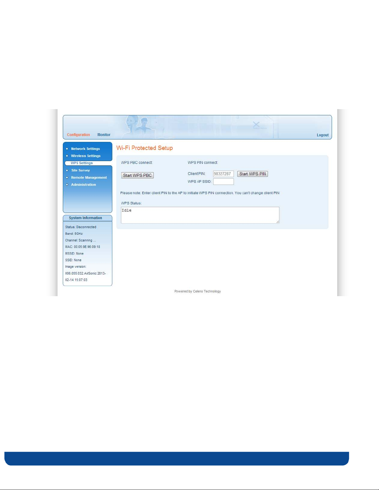
To define WPS settings in Client mode:
1. From the main menu of the VXT1836 Management Application, click Configuration
and from the Navigation Panel, click WPS Settings. The Configuration, WPS Settings
window appears.
Figure 102: VXT1836 Management Application – Configuration, WPS Settings Window
pg. 34 Copyright © 2012 Celeno Communications™ - All Rights Reserved | www.celeno.com
Page 35
The following table describes the actions that can be performed from this window:
Table 12: VXT1836 Configuration – WPS Parameters
Parameter Description
Start WPS PBC Button Initiates a WPS-PBC pairing procedure
Start WPS PIN Button Initiates a WPS-PIN pairing procedure
Client PIN A read only field that displayed the PIN code of the wireless
client device. This PIN code should be entered into the
appropriate field on the VXT1836 AP device WEB UI when
performing a WPS-PIN pairing procedure
WPS AP SSID This field is required for unit certification only to allow the
unit to act as WPS registrar, there is no need to use it in
normal mode operation
WPS Status Indicates the status of the WPS pairing procedure
2. Click Apply to update the settings offline. The system stores the new settings and
prompts you to restart the system.
3. Click YES and wait for the system to restart.
Note: A WPS-PBC pairing procedure can also be initiated by pressing the WPS button on the
front panel of the device.
Copyright © 2012 Celeno Communications™ - All Rights Reserved | www.celeno.com pg. 35
Page 36
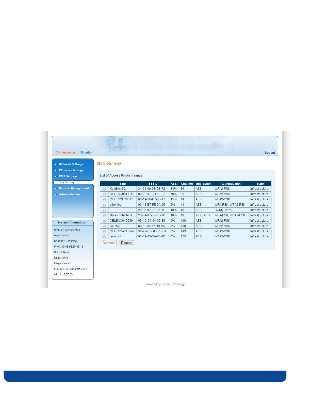
Site Survey (Client Mode Only)
The site survey window allows you to find and connect the VXT1836 client to a wireless
Access Point.
To find and connect to a wireless Access Point:
1. From the main menu of the VXT1836 Management Application, click Configuration
and from the Navigation Panel, click Site Survey. The Configuration, Site survey
window appears.
Figure 113: VXT1836 Management Application – Configuration, Site Survey Window
pg. 36 Copyright © 2012 Celeno Communications™ - All Rights Reserved | www.celeno.com
Page 37
The following table describes the parameters in the site survey table:
Table 93: VXT1836 Configuration – Site Survey table
Parameter Description
SSID Service Set Identifier. The code attached to beacon frames and
connection establishment frames.
BSSID Basic Service Set Identifier. This field uniquely identifies each
BSS.
RSSI The signal quality between the Access Point and the Client.
Channel The wireless channel that the Access Point is operating in.
Encryption The encryption scheme used by the Access Point.
Authentication The Authentication scheme used by the Access Point.
State Indicates if this is an Ad-Hoc connection or an infrastructure
network.
2. Select the Access Point you want to connect to and click the Connect button.
3. Click Apply and wait several seconds for the Client to connect.
Clicking the Rescan button initiates a new site survey scan and may temporary interrupt
the service to the wireless Client.
Copyright © 2012 Celeno Communications™ - All Rights Reserved | www.celeno.com pg. 37
Page 38
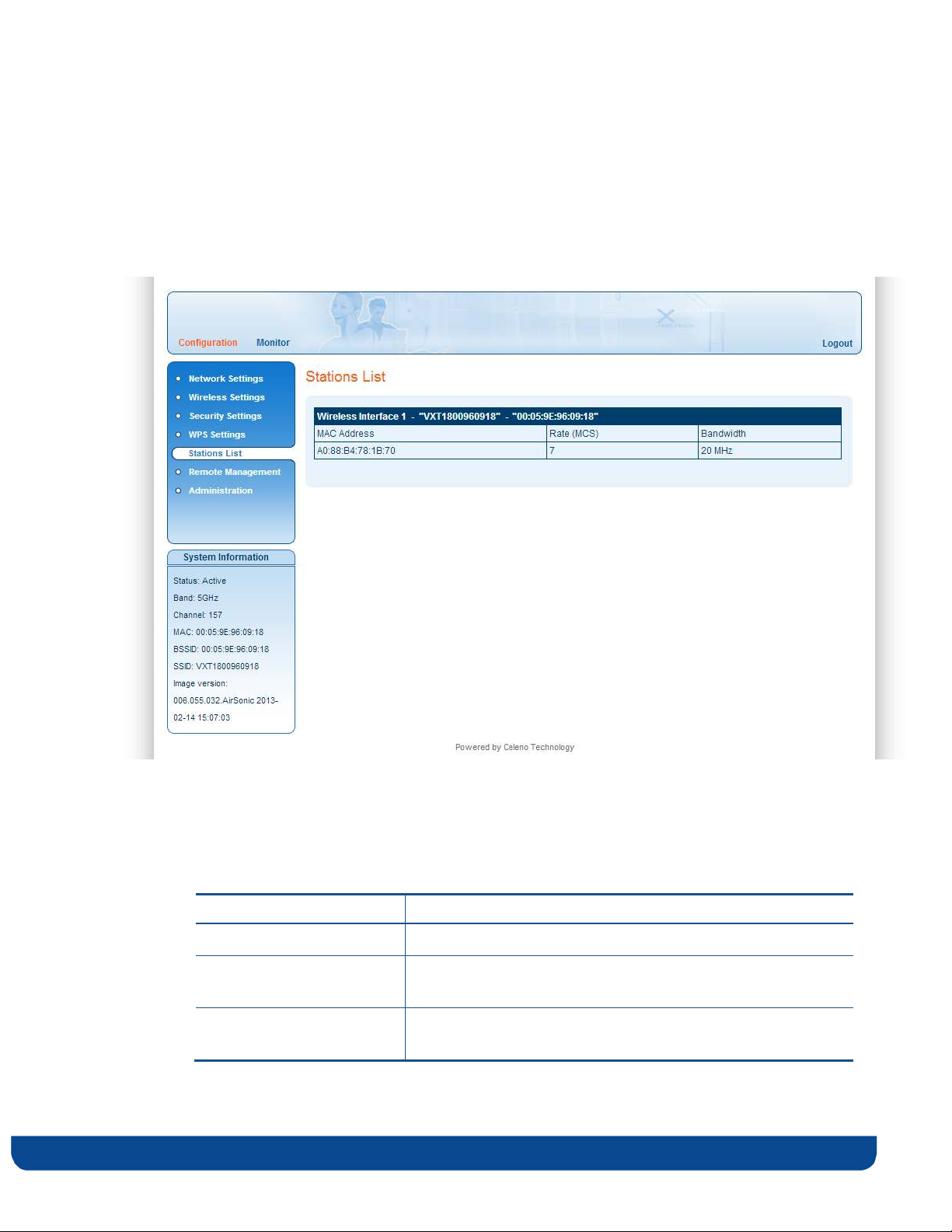
Stations List (Access Point Mode Only)
The Stations List window presents a list of clients connected to the VXT1836 Access Point.
Figure 124: VXT1836 Management Application – Configuration, Associated Stations List Window
The following table describes the parameters in the stations list:
Table 104: VXT1836 Configuration – Stations List
Parameter Description
MAC Address The MAC Address of the associated client.
Rate The modulation (physical data rate) that the Access Point
services the Client with.
Bandwidth The bandwidth that the Access Point uses when sending data
to the Client.
pg. 38 Copyright © 2012 Celeno Communications™ - All Rights Reserved | www.celeno.com
Page 39

Configuring Remote Management
The VXT1836 implements mechanisms that enable its remote management and trouble
shooting.
Remote Logging – When enabled, the VXT1836 periodically uploads event and
performance monitoring logs to a pre-designated FTP server.
UPnP – When enabled, the VXT1836 uses UPnP to access the home gateway device and
configure its port mapping table to enable accessing it remotely.
NTP – When enabled, the VXT1836 uses NTP protocol to obtain date & time.
TR-069 – When enabled, the VXT1836 device can be remotely provisioned using the TR069 management protocol.
To configure Remote Management settings in Access Point mode:
1. From the main menu of the VXT1836 Management Application, click Configuration
and from the Navigation Panel, click Remote management. The Configuration, Remote
Management window appears.
Copyright © 2012 Celeno Communications™ - All Rights Reserved | www.celeno.com pg. 39
Page 40
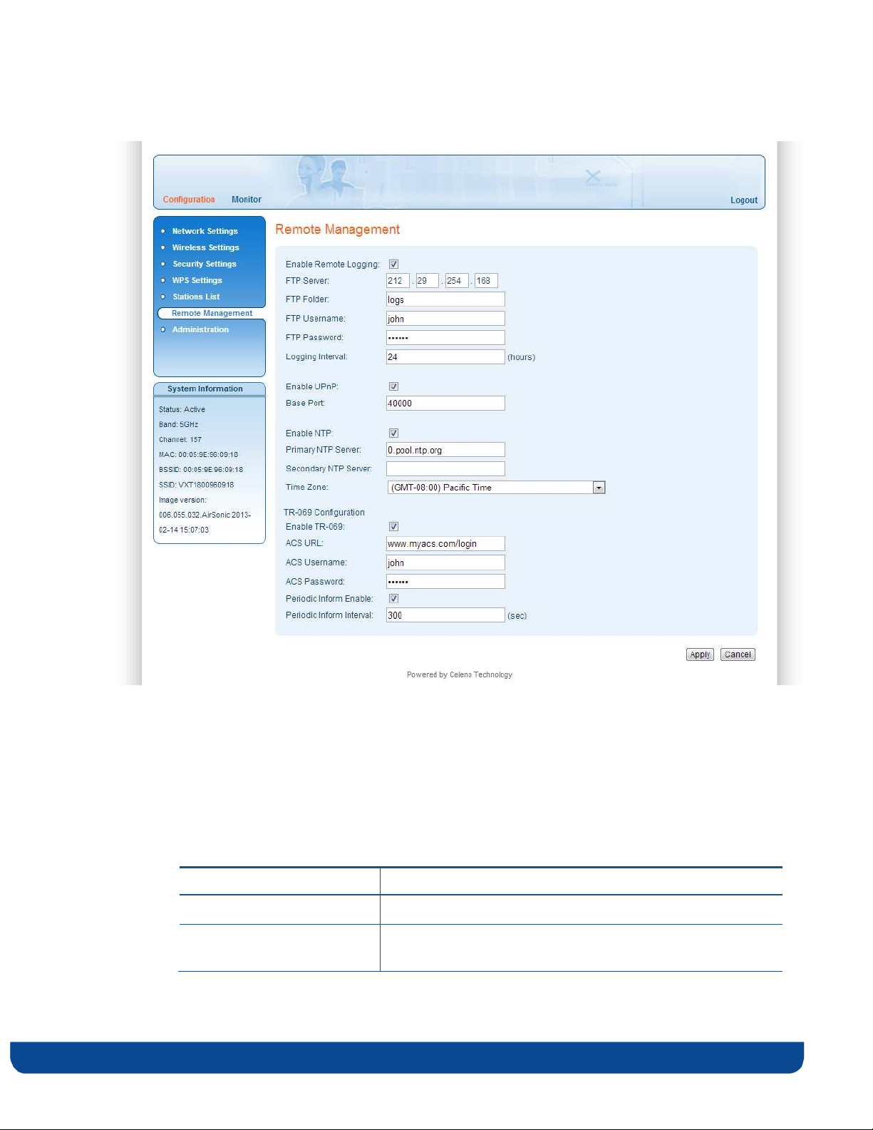
Figure 13: VXT1836 Management Application – Configuration, Remote Management Window
The following table describes the actions that can be performed from this window:
Table 11: VXT1836 Configuration – Remote Management
Parameter Description
Enable Remote Logging Enable / Disable Remote logging.
FTP Server The IP address of the FTP server onto which the logs will be
uploaded.
pg. 40 Copyright © 2012 Celeno Communications™ - All Rights Reserved | www.celeno.com
Page 41

Parameter Description
FTP Folder The folder name into which the logs will be uploaded.
FTP Username The FTP user name.
FTP Password The FTP password.
Logging Interval The period in hours of the scheduled log uploads.
Enable UPnP Enable / Disable UPnP based port mapping configuration in
the Home Gateway.
Base Port The port at the Home Gateway that the device will be
mapped to. In case that the selected port is already mapped
in the gateway, the next available port will be used.
Enable NTP Enable / Disable time synchronization with an NTP server.
Primary NTP Server The IP address of the primary NTP server
Secondary NTP Server The IP address of the secondary NTP server
Time zone The time zone the device resides in.
Enable TR-069 Configuration Enable / Disable remote provisioning using the TR-69
management protocol.
ACS URL The URL of the remote ACS (Automatic Configuration
Server)
ACS Username/Password The login credentials of the ACS.
Periodic Inform Enable When enabled the VXT1836 device connect periodically to
the ACS.
Periodic Inform Interval The time interval in seconds between periodic connection
attempts.
2. Click Apply to update the settings offline. The system stores the new settings and
prompts you to restart the system.
3. Click YES and wait for the system to restart.
Copyright © 2012 Celeno Communications™ - All Rights Reserved | www.celeno.com pg. 41
Page 42
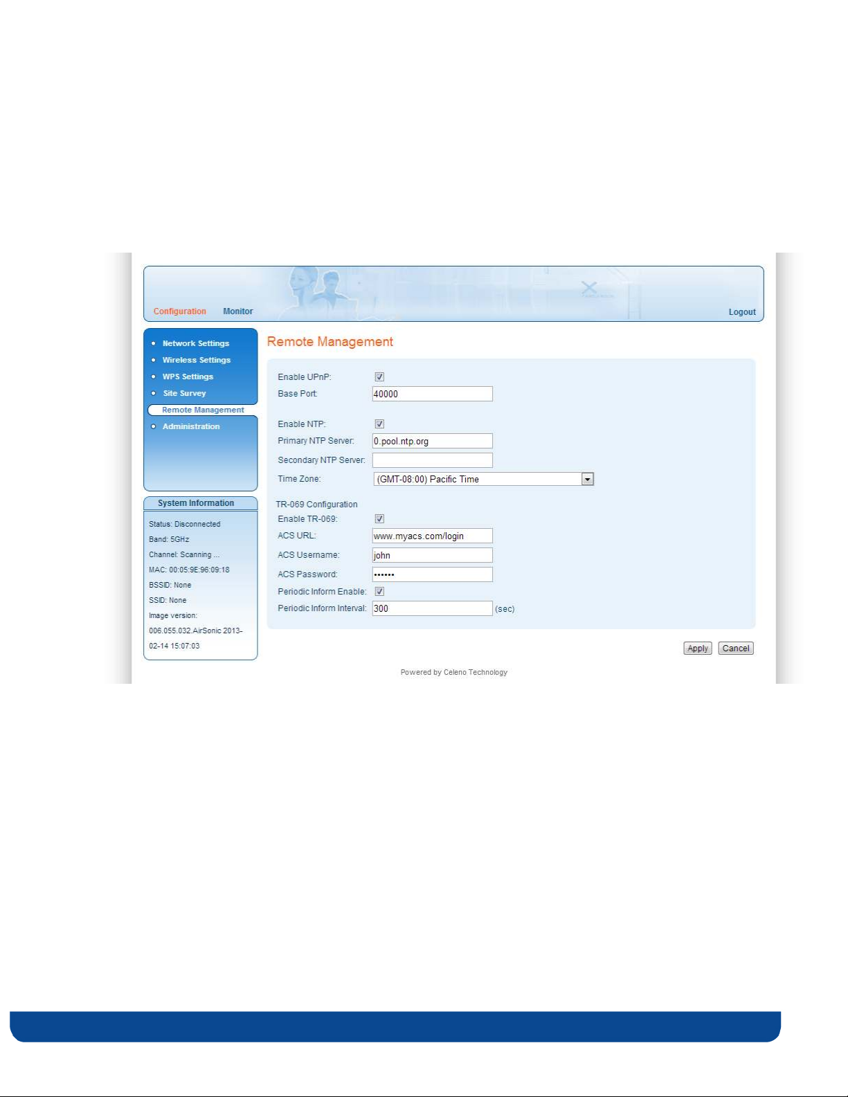
To configure Remote Management settings in Client mode:
1. From the main menu of the VXT1836 Management Application, click Configuration
and from the Navigation Panel, click Remote management. The Configuration, Remote
Management window appears.
Figure 14: VXT1836 Management Application – Configuration, Remote Management Window
pg. 42 Copyright © 2012 Celeno Communications™ - All Rights Reserved | www.celeno.com
Page 43

The following table describes the actions that can be performed from this window:
Table 12: VXT1836 Configuration – Remote Management
Parameter Description
Enable UPnP Enable / Disable UPnP based port mapping configuration in
the Home Gateway.
Base Port The port at the Home Gateway that the device will be mapped
to. In case that the selected port is already mapped in the
gateway, the next available port will be used.
Enable NTP Enable / Disable time synchronization with an NTP server.
Primary NTP Server The IP address of the primary NTP server
Secondary NTP Server The IP address of the secondary NTP server
Time zone The time zone the device resides in.
Enable TR-069
Configuration
ACS URL The URL of the remote ACS (Automatic Configuration Server)
ACS Username/Password The login credentials of the ACS.
Periodic Inform Enable When enabled the VXT1836 device connect periodically to the
Periodic Inform Interval The time interval in seconds between periodic connection
Enable / Disable remote provisioning using the TR-69
management protocol.
ACS.
attempts.
2. Click Apply to update the settings offline. The system stores the new settings and
prompts you to restart the system.
3. Click YES and wait for the system to restart.
Copyright © 2012 Celeno Communications™ - All Rights Reserved | www.celeno.com pg. 43
Page 44
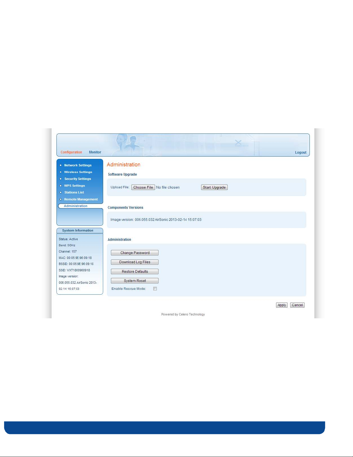
Performing Administration
To perform administration:
1. From the main menu of the VXT1836 Management Application, click Configuration
and from the Navigation Panel, click Administration. The Configuration,
Administration window appears.
Figure 15 - VXT1836 Management Application – Configuration, Administration Window
The Configuration, Administration window is divided into the following sections:
Software Upgrade
Flash Components
Control Buttons
pg. 44 Copyright © 2012 Celeno Communications™ - All Rights Reserved | www.celeno.com
Page 45

To perform Software Upgrade:
1. Click the Choose File button, select the new image file and press Open.
2. Click the Start Upgrade button; confirm the action by pressing OK in the confirmation
window and wait for the action to finish.
3. After the Software Upgrade finishes you can see the new software version number in
the System Information Panel.
Do not power off or reset the VXT1836 device while Software Upgrade is in progress.
Copyright © 2012 Celeno Communications™ - All Rights Reserved | www.celeno.com pg. 45
Page 46
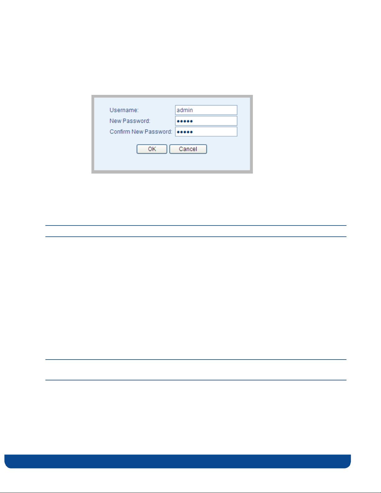
To change the password of the VXT1836:
1. Click the Change Password Button. The following window appears:
Figure 16 - VXT1836 Management Application – Change Password Window
2. Fill the new password details in the change password window and press OK.
3. After the successful completion of the operation you will be prompted to login again.
Note: Only a single user (admin) is supported in the current release.
To download log files from the VXT1836 device:
1. Click the Download Log Files Button.
2. A confirmation window will prompt you to confirm the download.
To restore the VXT1836 configuration to factory defaults:
1. Click the Restore Defaults Button; confirm the action by pressing OK in the
confirmation window and wait for the action to finish.
Note: You can also restore the VXT1836 device to factory defaults by pressing and holding the
Reset button for 10 seconds.
pg. 46 Copyright © 2012 Celeno Communications™ - All Rights Reserved | www.celeno.com
Page 47
To reset the VXT1836 device:
1. Click the Reset button; confirm the action by pressing OK in the confirmation window
and wait for the action to finish.
Note: You can also reset the VXT1836 device by pressing shortly on the Reset button.
To enable/disable rescue mode
1. Click the Enable rescue mode checkbox; confirm the action by pressing OK in the
confirmation window and wait for the action to finish. For further explanation see
troubleshooting section.
Copyright © 2012 Celeno Communications™ - All Rights Reserved | www.celeno.com pg. 47
Page 48
Monitoring the VXT1836 Device
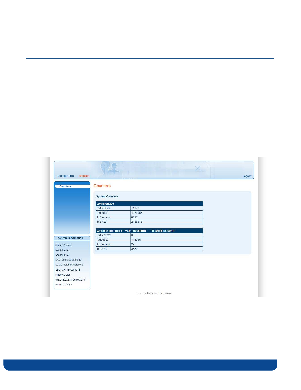
The VXT1836 Management Application Monitor displays information about the current
status of your VXT1836 Device. The system continually monitors a variety of network
parameters and displays them in the Counters window.
Viewing System Parameters
To view System Parameters:
From the main menu of the VXT1836 Management Application, click Monitor. The
Monitor, Counters window appears.
Figure 17: VXT1836 Management Application – Monitor, Counters Window
pg. 48 Copyright © 2012 Celeno Communications™ - All Rights Reserved | www.celeno.com
Page 49
Basic setup
Symptom
Advised solution
Make sure that
:
Make sure that:
Troubleshooting VXT1836 Kit
The power cord is connected to the device and that
the power adapter is properly connected to a
The Power LED is off
functioning power outlet.
You are using the power adapter that was supplied
with the product.
A
The LAN LED is off
The WLAN LED is not on
You are seeing artifacts on
the TV screen
No access to the VXT1836
The LAN cable connectors are securely plugged in at
the wireless video extender device and at the
network device (gateway, modem or set-top box).
The connected network device is turned on.
You are using the correct cable type for your
Ethernet equipment that is at least UTP CAT5 with
RJ45 connectors.
Make sure that you have completed a successful
pairing procedure as described in "Pairing your
Devices" on page 13 herein.
Make sure that the wireless video extender devices
are placed according to the recommendation in
Placing and Connecting your on page 13 herein.
Make sure that your computer IP address is
Copyright © 2012 Celeno Communications™ - All Rights Reserved | www.celeno.com pg. 49
Page 50

Basic setup
Symptom
Advised solution
web
control
page
s. 10.
XXX.
YYY.
ZZZ
and its
subnet mask
is
255.0.0.0.
If your VXT1836 IP address has been changed,
please assign the computer an IP address in the
same range as the VXT1836 IP Address.
Remember: Whenever a change is made in the Setup of the
Access Point, the Apply button must be used to save the
settings to the Access Point.
Remember: The Access Point control web page is not
accessible from the wireless client/adapter segment.
pg. 50 Copyright © 2012 Celeno Communications™ - All Rights Reserved | www.celeno.com
Page 51

Using Rescue Mode:
Rescue mode enables the VXT1836 client to update its firmware version from the AP. If
enabled, this mode can be used for one of two purposes:
• To synchronize firmware versions between AP and client.
• To recover the client in the case of firmware damage.
How to perform firmware upgrade in rescue mode:
1. In order to update the client firmware version from the AP, connect both devices via
Ethernet cable while both of them are off.
2. Power up the AP device and wait one minute until boot process finishes.
3. Power up client device and monitor the process through LED behavior. It may take up
to 5 minutes.
4. At first, client power LED will blink for 5 seconds. After that, all LEDs on both AP and
client will be solid on for about 2 minutes. Next, client power LED will be off for 5
seconds and then both devices will reboot themselves. As the boot process ends you
can power off the two boards and reconnect them within the network topology as you
wish.
Copyright © 2012 Celeno Communications™ - All Rights Reserved | www.celeno.com pg. 51
 Loading...