

Page 1

CORONDO CONTROLS LTD
BOLTON BL1 2PT
www.coronadocontrols.com
C
ELECT
DRF3
RF Thermostat
Instruction Manual
Page 2
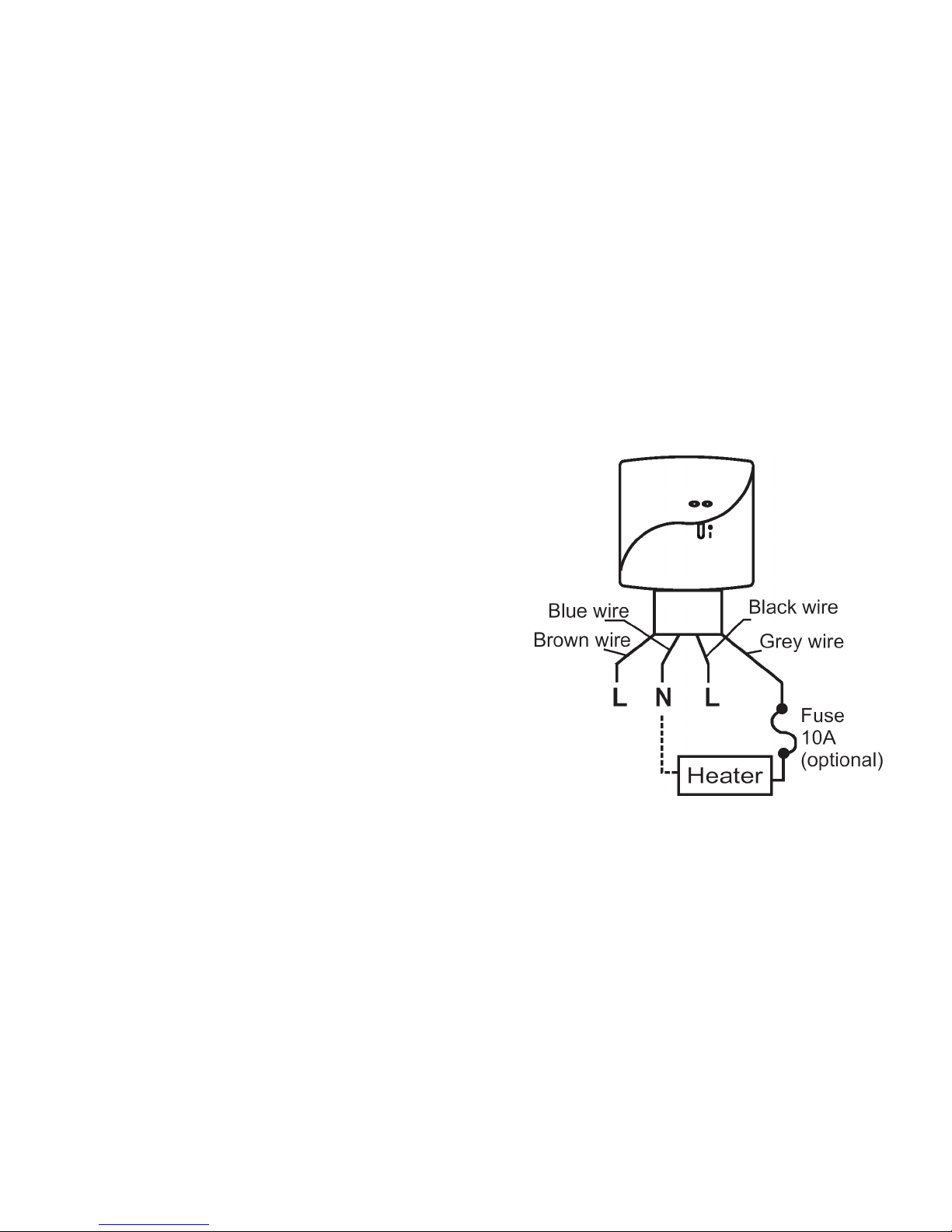
TABLE OF CONTENT
A. Installation and Mounting ………………….. 3
1. Installation …………………………………… 3
2. Wiring ………………………………………...
4
3. Mounting ……………………………………..
4
B. Start/Reset …………………………………... 6
C. Normal Time Mode ………………………….
7
D. Temperature Setting Up ….………………… 7
E. Jumper Selection …………………………...
8
F. Address Setting …………………………..…
8
G. Specification ……………………………..…..
9
1
Terminal block connecting Label:
10
Page 3

G. Specification:
1. Temperature measurement:
0.0 - 40°C
(0.1°C/step)
2. Accuracy: ± 0.5°C
3. Temperature control range:
5.0 - 35.0°C
(0.5°C/step)
4. Terminals:
2.5mm2 cable
5. Electronic control: Type 2.B action
6. Transmitter—Battery:
2 x 1.5V AAA alkaline
battery
7.
Receiver—Input voltage: 240Vac
8.
Receiver—Output voltage: 24..240Vac 50/60Hz
10(3)A max
9. Operating temperature: 0 - 50°C
10. Storage temperature:
-10 - 60°C
11.Sensing Element:
NTC thermistor
9
DRF3 RF Thermostat
1. The system includes one wireless thermostat controller
plus one RF receiver.
2. Transmits up to 20 meter indoor.
3. Communicates at 868MHz (Europe Standard) and
designed for unlicensed operation under FCC Part 15.
Warning:
1. If there is a dead zone in the RF communication. That
means the receiver may not be able to receive the
message from the transmitter. Before the installation,
check the communication first. If the communication
fails, relocate the receiver and transmitter location.
2.
If the receiver has interference, set another transmitter
address. Reset the transmitter and follow the set up
instruction to reset the receiver.
3. It is recommended locate at least 30com distance from
any metal objects (including the metal box) and at least
2 meter from any electronic devices e.g. radio TV, PC,
2
Page 4
etc. The metal objects or electronic devices maybe
interfere with the RF communication, so maximum
distance will be shorter.
4. Do not mount onto metal wall boxes.
A. Installation, Mounting:
Caution:
Turn off DRF3 and the electrical devices (e.g. heater,
cooler) which will be connected before installation.
It is highly recommended that the installation procedure
is processed by trained personnel.
1. Installation Location:
The thermostat (Receiver and Transmitter) should be
mounted on an inner wall 1.5m above the floor in
position where it is readily affected by changes of the
general room temperature with freely circulating air.
Prevent direct exposure to sunlight; dripping or
splashing area.
Do not place this unit at a location where air circulation is
3
2. Return the room temperature display after 10seconds
with the < > icon disappears.
E. Jumper Selection:
Delay / No Delay jumper:
Heater Cooler
No delay 10sec 4mins
Delay 4mins 4mins
Choose the Delay option if compressor heat is connected.
Heater/Cooler jumper:
Select the heater option when a heater is connected to
the receiver. Select the cooler option when a cooler is
connected to the receiver.
F. Address setting:
In transmitter and receiver, there are dip switches to
select the addresses. The receiver ignores the message
which is sent by the transmitter with different address
8
Page 5
3.Switch ON the heater/cooler and receiver. The
heater/cooler will remain OFF until transmitter activates
the output ON with
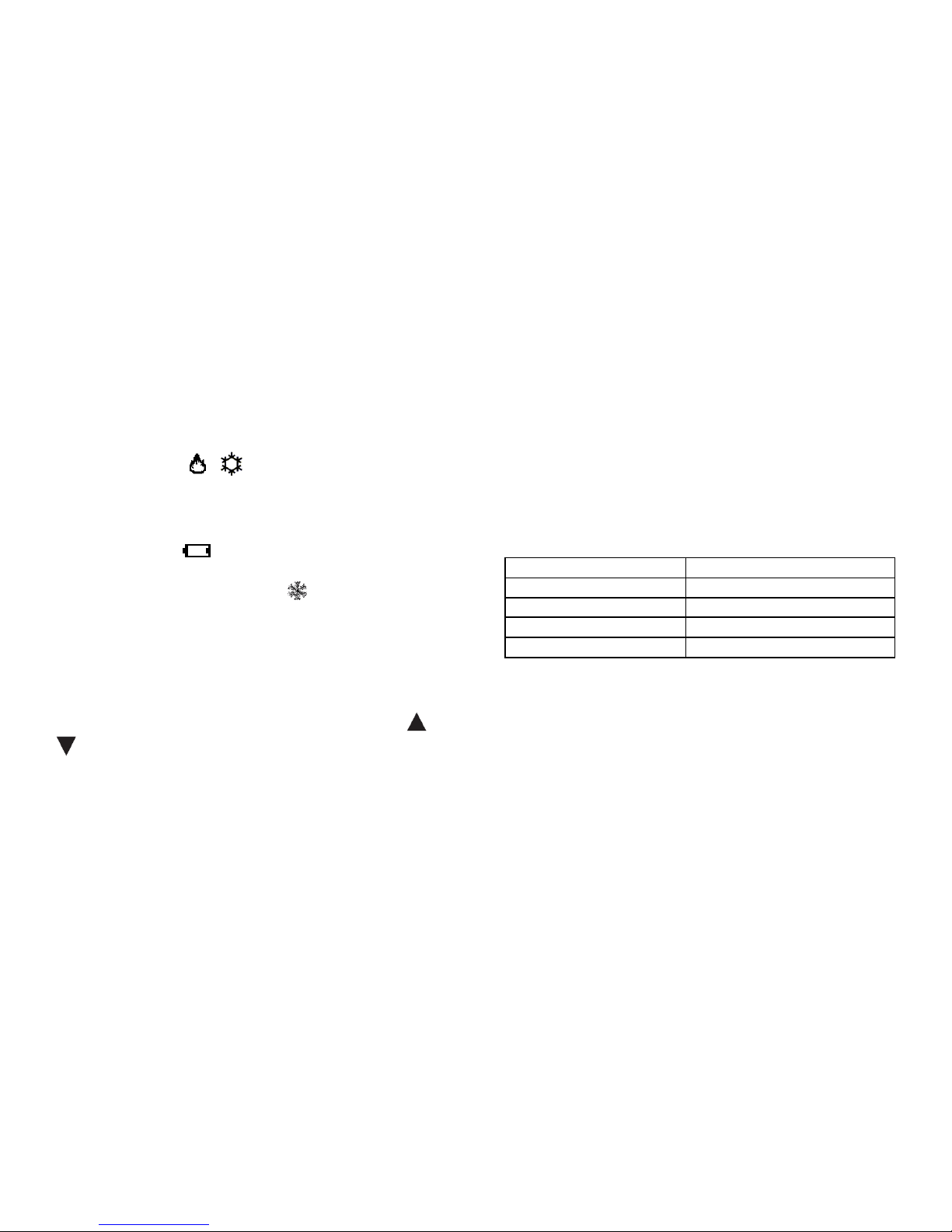
/ displayed on LCD.
C. Normal Time Mode:
1. Temperature detection starts and LCD displays the room
temperature.
2. If Battery is LOW, will be On. The old batteries must
be replaced with new one immediately.
3. Defrost function is activated with displayed when
temperature is 5°C or below. Output will be forced to ON
@ Heat & OFF @ Cool.
4. Below 0°C, transmitter will display LO.
5. Above 40°C, transmitter will display HI.
D. Temperature Setting Up:
1. Select the comfortable temperature by pressing < > or
< > to desirable temperature.
7
low, or where it has great temperature changes (e.g. near
door). Do not place the thermostat near heat/cool
generating sources.
2. Wiring:
Caution: Turn off the electrical devices and receiver
before wiring.
There is 4-wire cable provided
Color Connection
Brown 240Vac Live
Blue 240Vac Neutral
Black 240Vac Live
Grey Device’s power input
-It is recommended that a 10A fuse is fitted at grey wire.
(Please refer to the wiring diagram on the last page.)
3. Mounting:
Using the accessory screws and wall anchors provided,
mount DRF3 with the key-hole at the back. The
transmitter and receiver should be mounted on the wall
4
Page 6
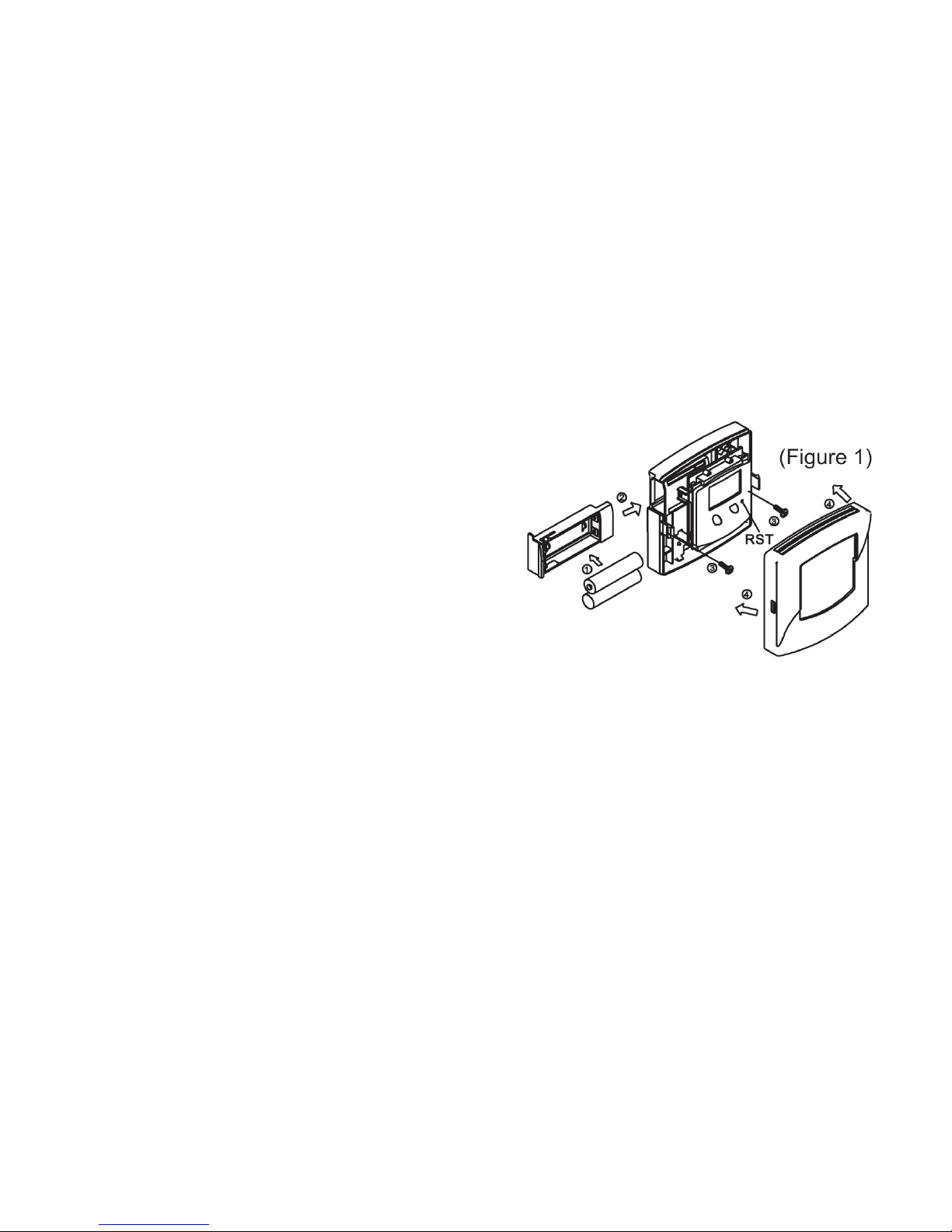
and install the covers on them.
Install or replace the battery for transmitter:
Caution: Turn off the electrical devices and disconnect
the supply to the appliances before replacing the
batteries. Replace only with the same or equivalent type
of batteries. Do not dispose the used batteries with
household waste. Refer to your local area for the proper
disposal.
1. Pull out the battery drawer
2. Place the new batteries according to the marking on
the battery drawer.
3. Dispose the old batteries properly. Slide the battery
drawer back to its position.
4. Check if the thermostat works properly or not. Press
“Reset” if necessary.
5
B. Start/Reset:
1. After wiring and mounting, switch off all the connected
devices. Place 2 new AAA 1.5V alkaline batteries
according to the polarities marked.
LCD display will be switched on.
2. Press ‘RST’ to reset. The DRF3 will be ready to control
the heater / cooler.
6
DRF3 Transmitter Installation
 Loading...