

Page 1
Thank you for choosing Celcom Broadband
Wireless Gateway - 3GX (HSDPA) + WIFI
Copyright © 2008 Huawei Technologies Co., Ltd.
All Rights Reserved
No part of this manual may be reproduced or transmitted in any form or by any
means without prior written consent of Huawei Technologies Co., Ltd.
Trademarks
and HUAWEI are trademarks of Huawei Technologies Co., Ltd. All other trademarks
and trade names mentioned in this manual are the property of their respective
holders.
Notice
The information in this manual is subject to change without notice. Every effort has
been made in the preparation of this manual to ensure accuracy of the contents, but
all statements, information, and recommendations in this manual do not constitute
the warranty of any kind, expressed or implied.
(Model No: E961)
Page 2
Safety Precautions
Read the safety precautions carefully to ensure the correct and safe use of your wireless
device. For detailed information, see “Warnings and Precautions.”
Do not switch on your device when the device use is prohibited
or when the device use may cause interference or danger.
Do not use your device while driving.
Follow the rules or regulations in hospitals and health care facilities.
Switch off your device near medical apparatus.
Switch off your device in an aircraft. The device may cause
interference to control signals of the aircraft.
Switch off your device near high-precision electronic devices. The
device may affect the performance of these devices.
Do not attempt to disassemble your device or its accessories. Only
qualied personnel are allowed to service or repair the device.
Do not place your device or its accessories in containers with
strong electromagnetic eld.
Do not place magnetic storage media near your device. Radiation
from the device may erase the information stored on them.
Do not put your device in a high-temperature place or use it in a
place with ammable gas such as a gas station.
Keep your device and its accessories away from children. Do not
allow children to use your device without guidance.
Use approved accessories only to avoid explosion.
Observe the laws or regulations on device use. Respect others’
privacy and legal rights when using your device.
Page 3

Table of Contents
1 Getting to Know Your E961 1
Appearance 1
Recommended PC Requirements 2
2 Quick Start 3
Gateway Mode 3
Using the E961 User Guide 4
3 Using the E961 Configuration Page 5
Logging in to the Management 5
Describing the Management 6
Using the Quick Setup Wizard 7
Connecting to the Internet 7
Validating the PIN Code 8
Viewing the Gateway Configuration Information 8
4 Quickly Configuring the Gateway 9
Configuring PPP Profile Settings 9
Selecting the PPP Connection Mode 10
Configuring the WLAN Setting 10
Configuring the WLAN Encryption Mode 11
Validating Quick Setup 12
5 Configuring Your Computer 13
Wireless Configuration 13
Configuring the PC Network 14
6 Describing Advanced Settings 16
7 Managing the System 18
Modifying the Password 18
Upgrading the Gateway 19
Restoring Factory Defaults 20
Restarting the Device 20
Viewing the Version Information 20
Page 4

Table of Contents
8 Configuring SIM Card Settings 21
Enabling or Disabling the PIN Code 21
Unlocking the PIN Code 22
Modifying the PIN Code 22
9 Configuring UMTS Settings 23
Choose the Preferred Mode and Band 23
Configuring the Mode for Searching Network 25
10 Configuring Dial-up Settings 26
Configuring PPP Settings 26
Managing the Profile List 27
11 Assigning IP Addresses 29
12 Configuring the WLAN 30
Enabling or Disabling the WLAN 30
Configuring WLAN Settings 30
Advanced WLAN Settings 32
Configuring the MAC Filter 34
14 Typical Networking Example 39
15 Troubleshooting 40
16 Warnings and Precautions 41
17 Abbreviations 43
13 Security Settings 35
Firewall Switch 35
LAN MAC Filter 36
LAN IP Filter 36
Virtual Server 37
DMZ Service 38
UPnP Settings 38
Remote Management 38
Page 5
Getting to Know Your E961
1
Your E961 supports UMTS/HSDPA 2100MHz GSM/GPRS/EDGE 850/900/1800/1900MHz, and
network auto-switch. With the E961, you can experience wireless gateway at any time and
any place.
Appearance
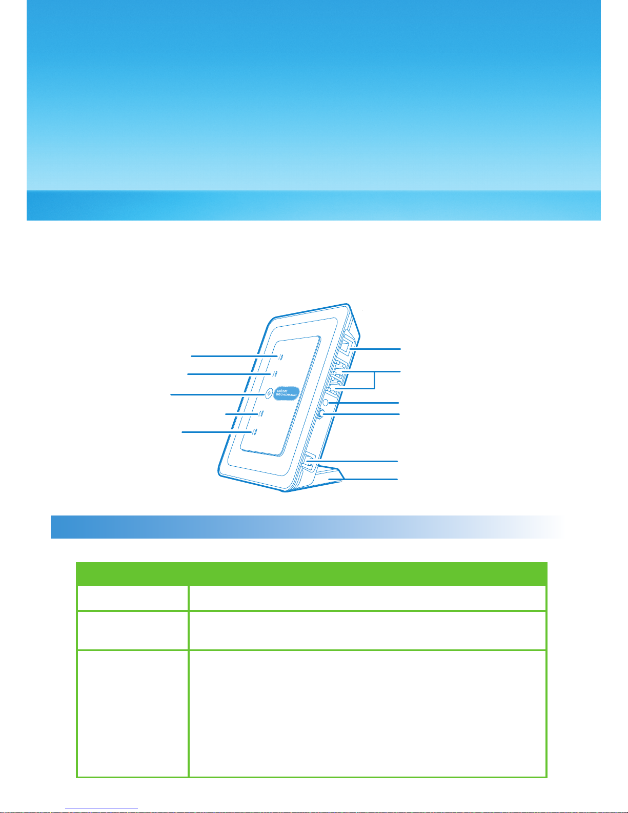
Indicator and Button
The following table introduces the indicator and button of your E961.
Power
When it is in yellow, the gateway is switched on successfully.
WLAN If it is steady on and in yellow, the WLAN is enabled. If it is
blinking, data is transmitting
Signal strength • Fast blinking in red : No SIM card or unveried PIN code
• Steady on in red : Signal strength in level one (weak)
• Steady on in yellow : Signal strength in level two or three
(middle)
• Steady on in green : Signal strength in level four or ve
(strong)
Indicator
* Set the Antenna Selector to Internal unless the gateway is connected to an External Antenna
Power Indicator
WLAN indicator
ON/OFF key
Signal Strength Indicator
Network Mode
Indicator
Phone
Ethernet
External Antenna Connector
Antenna Selector
Power Adapter
Pedestal
1
Page 6

Network mode • Double blinking in green: Searching the network
• Blinking in green: Normal 2G network
• Steady on and in green: GPRS/EDGE data service
connected
• Fast blinking in green: Downloading the upgrade mode
• Blinking in blue: Normal UMTS network
• Steady on in blue: UMTS data service connected
• Steady on in cyan: HSDPA data service connected
Note: When the gateway is initialized, it is steady on in
green for three seconds.
Button
ON/ OFF Press and hold it to power on or off the E961
Recommended PC Requirements
The recommended PC congurations for using and conguring the E961 are as follows:
• CPU: Pentium 500 MHz or above
• Memory: 128 MB RAM or above
• Hard disk: 100 MB available space
• Operating System: Windows 2000,
Windows XP, or Windows Vista
• LCD resolution: 800*600 pixel or above,
recommended 1024*768 pixel.
• Internet Browser: Internet Explorer 6.0
or above, Firefox 1.5 or above,
Netscape 8.0 or above
External Interfaces
• Two LAN Interfaces (RJ45)
• One telephone interface (RJ11)
• WIFI 802.11b/g and multiplex for power supply
2
Page 7
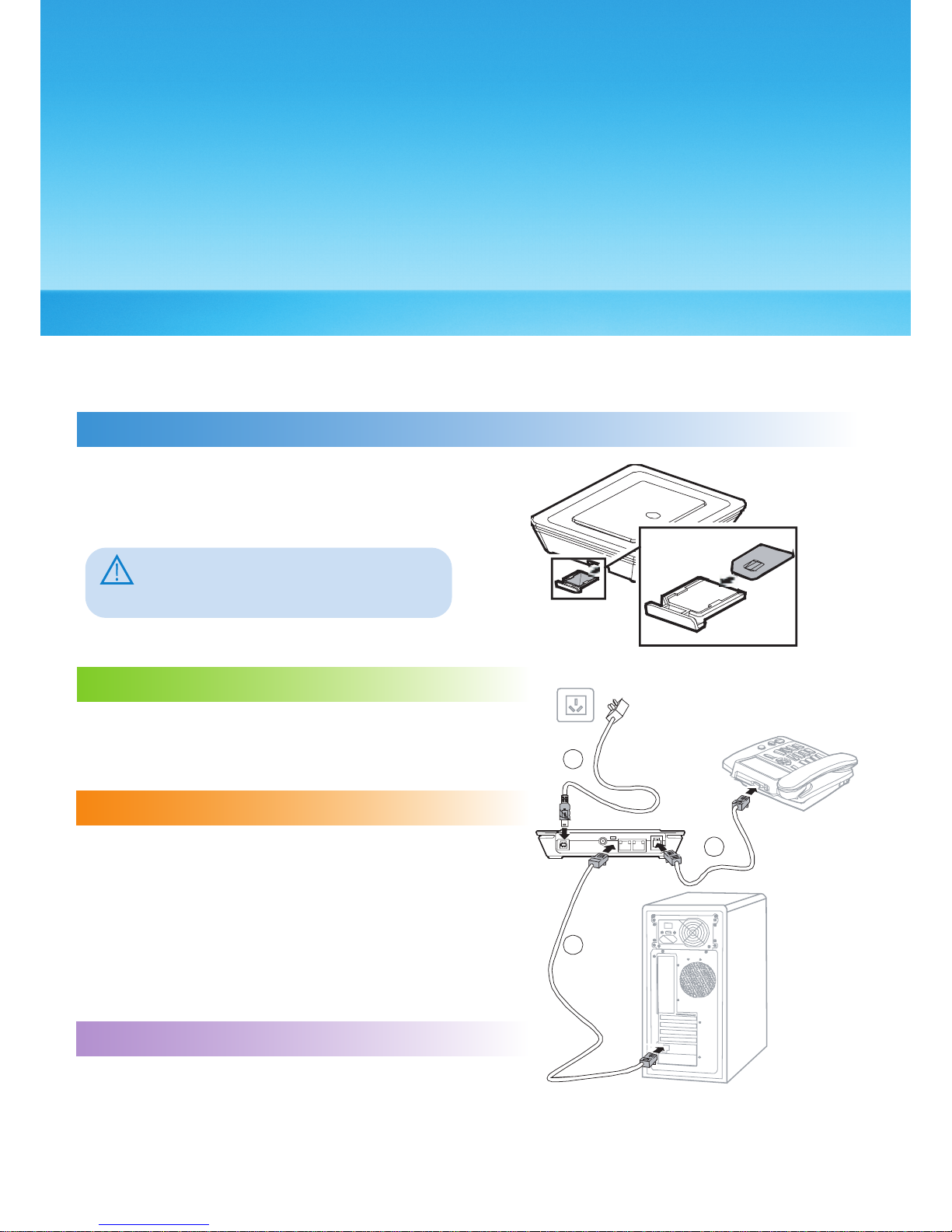
Step 1: Insert the SIM Card
1. Take out the card socket from the E961.
2. Insert the SIM card into the socket with the
golden contact facing upward.
3. Insert the card socket into the E961.
Caution:
When inserting or removing the SIM card,
you must disconnect the E961 from the
power adapter.
Quick Start
2
Gateway Mode
Step 2: Connect the Power Adapter
Please use the E961 compatible power adapter;
otherwise, the E961 can be damaged.
Step 3: Connect to a PC
If the indicator of the Ethernet interface
connecting with a network cable is on, the
connection is successful. The Ethernet cable
cannot be longer than 100 meters (328 feet). For
better effect, please use the shielded cable.
2
4
3
Step 4: Connect to a telephone set
* Please ensure that the LAN and WIFI interface in the PC
or Laptop is configured for DHCP IP address settings.
* The WIFI SSID for the gateway is “Celcom Broadband”
3
Page 8
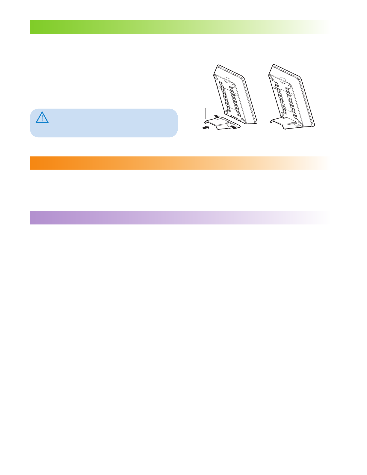
Step 5: Place the E961
The E961 can be placed horizontally on a table, hanging against wall, or leaning against
the pedestal. Place the E961 on a higher place or near the window, so it can receive
better signal strength.
Press the bayonet of the pedestal, and
place the E961 into the pedestal as
shown in the figure. Thus, the E961 can
lean against the pedestal.
Caution:
To avoid electrical devices from interfering
by the wireless signal, place electrical
devices one meter away from the E961.
Step 6: Internet Access
By default, the E961 connects to access the internet via Celcom Broadband connection
automatically. You can directly use the network service such as web browsing, and
receiving or sending emails.
Step 7: Making a Call
When you hear the dial tone after picking up the handset, you can make a call. Call
charges is based on your subscribed voice package.
1. Insert your E961 User Guide CD into your PC.
2. Access My Computer.
3. Access the CD/DVD Drive with the descriptor “User Guide.”
4. Double-Click on the “E961UserGuide.pdf” file.
4
Using the E961 User Guide
Step 5
Page 9
Using the E961 Conguration Page
3
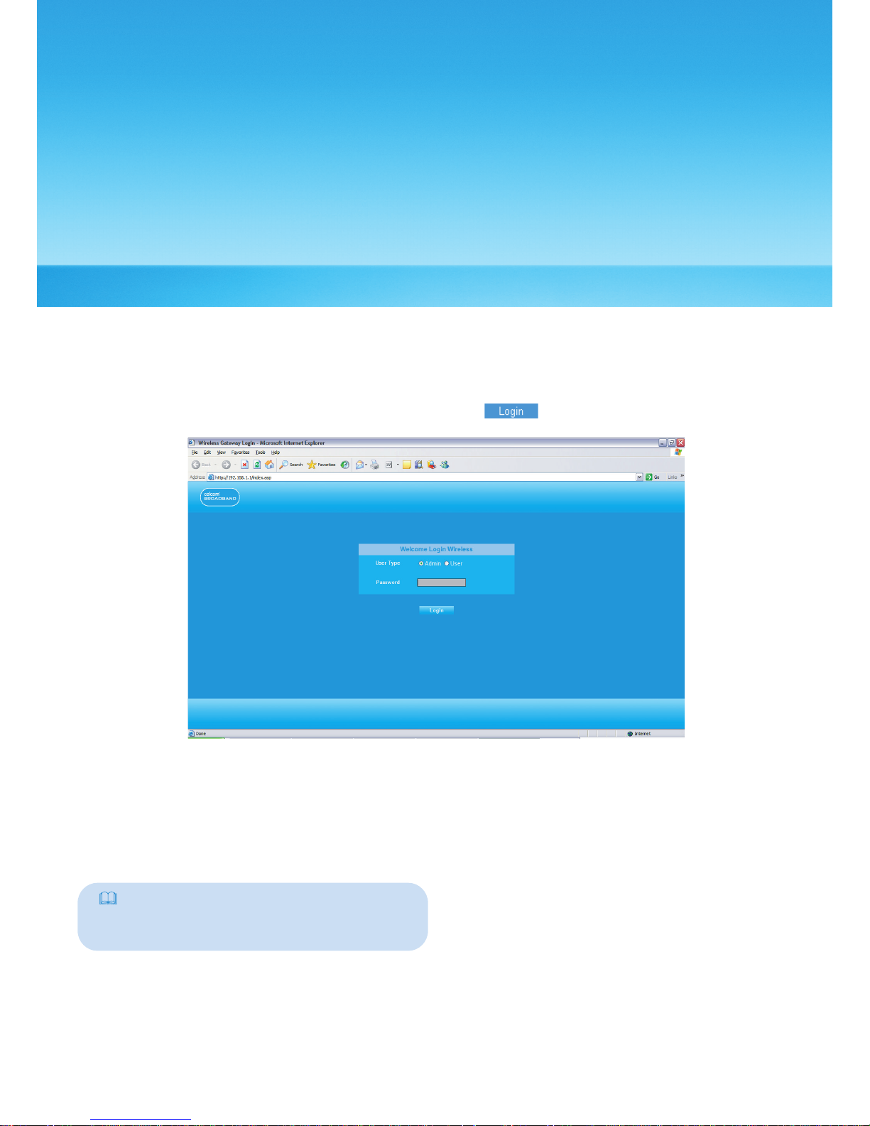
Logging in to the Management Page
1. Start the IE browser, and then enter the address http://192.168.1.1 in the address bar.
2. Select User Type, enter Password, and then click .
• Admin : Has the rights to view and modify the congurations. The default password
is admin;
• User : Has the right to view only the basic information. The default password is user.
Note:
To avoid the conguration conict, only one
user can log in to the E961 management
page at a time.
5
Page 10
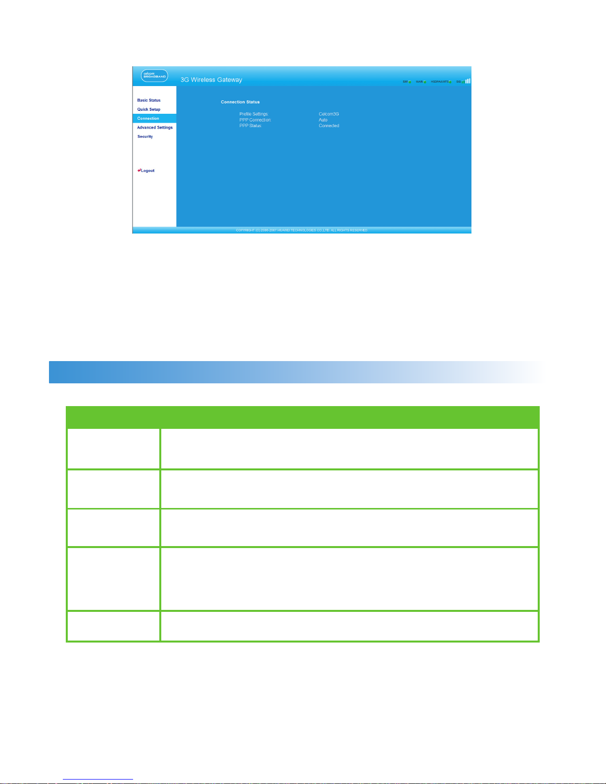
Describing the Management Page
• Operation Navigation Area: Shows the main functions of the management console.
• User Operation Area: Shows conguration information, data information, help
information, and function operation area of the gateway. The user operation window
varies with different function operations.
• Status Display Area: Shows the network mode, PPP dial-up status, network signal
strength, and SIM card status in real-time.
Operation Functions
The following table shows the main operations in the gateway management page.
Item Description
Basic Status Displays the parameter conguration status of the gateway. For
details, see “Viewing the Gateway Conguration Information.”
Quick Setup Congures the gateway quickly. For details, see Chapter 4
“Quickly Conguring the Gateway.”
Connection Displays the network connection status and connects to the
network. For details, see “Connecting to the Internet.”
Advanced Congures the advanced settings of the gateway, which includes
Settings the following settings: system, SIM card, UMTS / WCDMA, dial-up,
DHCP, and WLAN. For details, see Chapter 6 “Describing
Advanced Settings.”
Logout Log out of the gateway page.
6
Page 11
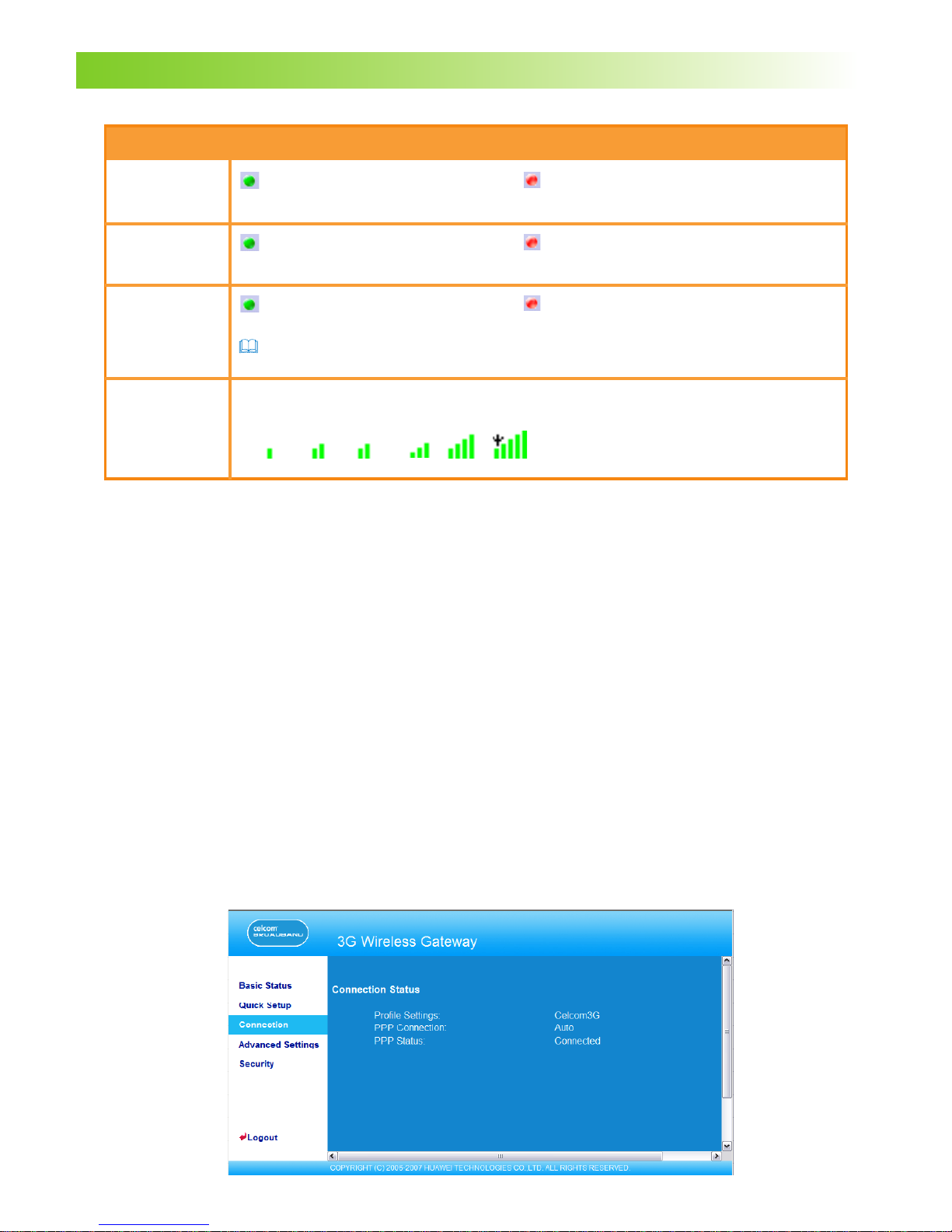
Gateway Status
The following table shows the gateway status information.
Item
SIM
WAN
WCDMA
SIG
Description
The SIM card is valid.
The PPP dial-up connection
is successful.
The UMTS / WCDMA network
is connected.
Note : If the gateway is registered with other network modes, the corresponding
network connection status is displayed.
The signal strength from weak to strong is shown as follows:
The SIM card is not inserted
or invalid.
The PPP dial-up connection is
failed.
The UMTS / WCDMA network
is unavailable.
Using the Quick Setup Wizard
The quick setup wizard guides you to congure the most important settings of the
gateway.
If you are using the gateway conguration page for the rst time, the system displays the
quick setup wizard page by default after you log in. You can congure the basic parameters
quickly by following the prompts. For details, refer to “Quickly Conguring the Gateway.”
Connecting to the Internet
Accessing the Connection Status Page
• Click Connection to access the page.
• After you log in to the management page again, you can automatically access the
connection status page.
7
Page 12
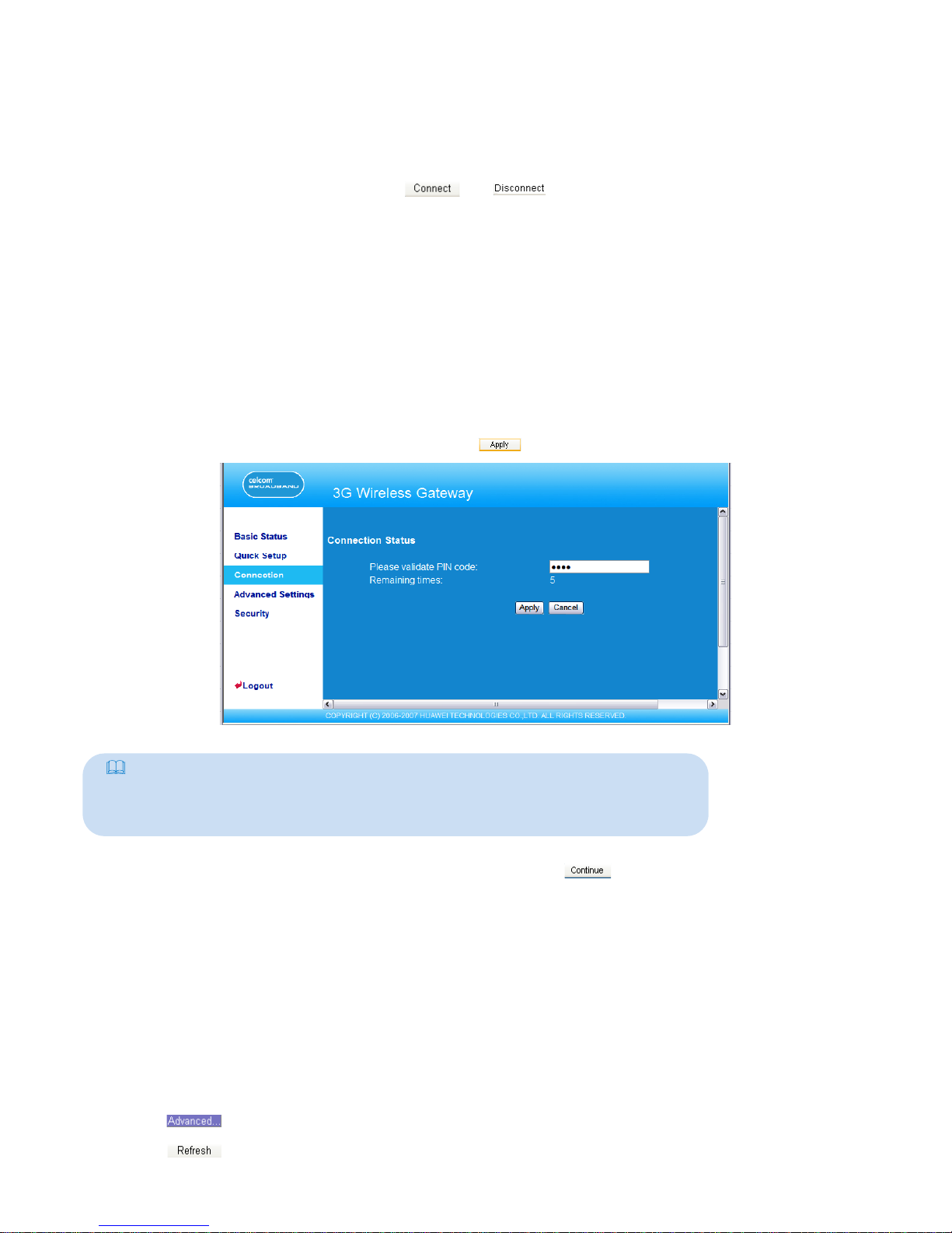
Connecting to the Internet
1. If the PIN code protection is enabled, the system prompts you to validate the PIN code.
For details, see “Validating the PIN Code.”
2. If PPP Connection is Auto or Demand, refresh the page to view the current network
connection status.
3. If PPP Connection is Manual, click or to connect or disconnect from the
network.
4. Wait for several minutes, if you are prompted that the connection is successful, you can
start the IE browser and enter the website address to access the Internet.
Validating the PIN Code
If the PIN code protection is enabled, you are prompted to validate the PIN code when
you restart the gateway and log in to the management page.
1. Enter the correct PIN code, and then click .
Note:
• The default PIN Code is “1234”.
• If you enter wrong PIN codes for three successive times, the PIN is locked.
For details, see “Unlocking the PIN Code.”
• If the PIN validation fails, you cannot use the network-related functions.
Viewing the Gateway Conguration Information
On the gateway conguration page, you can view the current parameter conguration
information of the gateway and the network connection status. The network connection
status includes WAN, LAN, and WLAN.
1. Click Basic Status in the operation navigation area.
2. Click on the right part of the page to view the status of the gateway.
3. Click to view the current status of the gateway on the advanced status page.
2. When you succeed in validating the PIN code, click to access the network
connection page.
8
Page 13
Quickly Conguring the Gateway
4
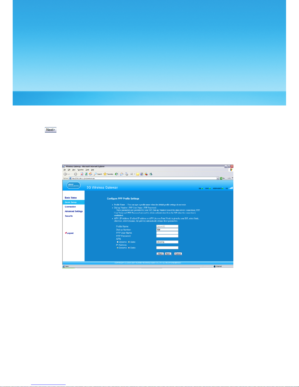
You can use the quick setup wizard to congure and maintain the basic parameters of the
gateway. Click Quick Setup in the operation navigation to access the welcome page.
Click to access the PPP prole setting page following the page prompts.
Conguring PPP Prole Settings
• Prole Name: Enter the prole name when the text box is null.
• Dial-up Number/PPP User Name/PPP Password: Enter these three parameters provided
by the internet service provider (ISP). The dial-up number is used to initiate the network
call; and the PPP user name and password is used to gain the service authorization
provided by the ISP.
• APN/IP Address: Select the mode for obtaining the APN or IP address. If the carrier
provides the relevant parameters, select Static and enter the APN and IP address.
Otherwise, you need to select Dynamic and the gateway automatically obtains them.
9
Page 14
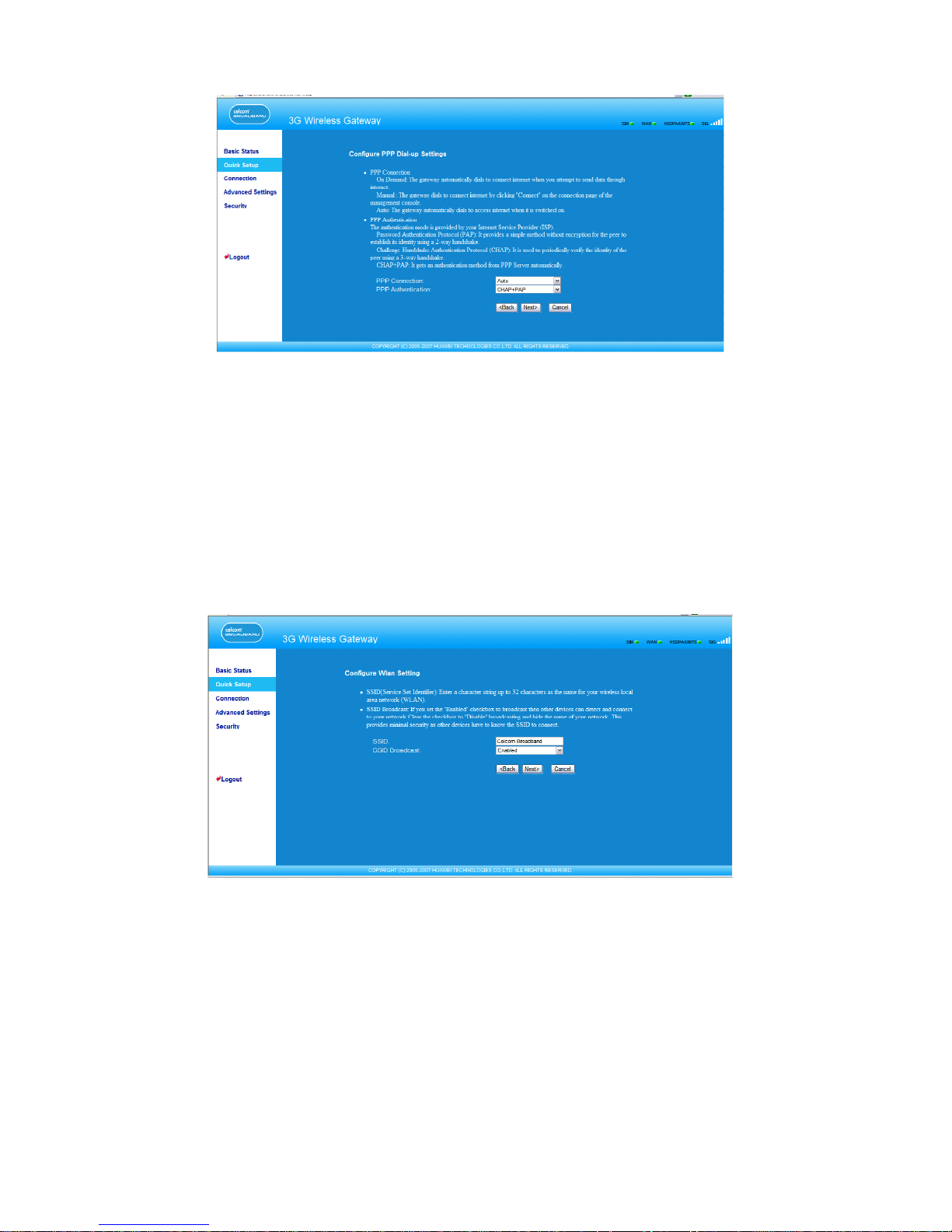
Selecting the PPP Connection Mode
PPP Connection: It is used to select the dial-up access mode.
• Auto: After the gateway is switched on, it automatically connects to the Internet and will
not disconnect regardless of the data transmission.
• On Demand: The gateway automatically connects to the Internet when there is data
transmission. It automatically closes the connection when there is no data transmission.
• Manual: Manual dial-up. For details, see “Connecting to the Internet.”
Conguring the WLAN Setting
SSID: Enter a name for your WLAN.
The service set identier (SSID) is used to identify a WLAN. A wireless terminal (such as a
PC) and the wireless gateway can perform normal data communication only when they
have the same SSIDs. To ensure the WLAN security, do not use the default SSID. You can
enter a character string as the SSID, such as MyHome.
SSID Broadcast: Enable or disable the SSID broadcast.
• Enabled: The E961 broadcasts the SSID of the WLAN, and users can easily access the
WLAN. Unauthorized users, however, can also easily access the WLAN because the SSID
is broadcasted.
10
Page 15
Note:
For the convenience of the client accessing the WLAN, you can select
Enabled for SSID Broadcast when you congure the WLAN setting. Once you
nish setting up the WLAN, you can disable the SSID broadcast to improve the
security of the WLAN.
• Disabled: The E961 does not broadcast the SSID of the WLAN. Before accessing the
WLAN, the user must obtain the SSID of the WLAN. Thus, the WLAN security is improved.
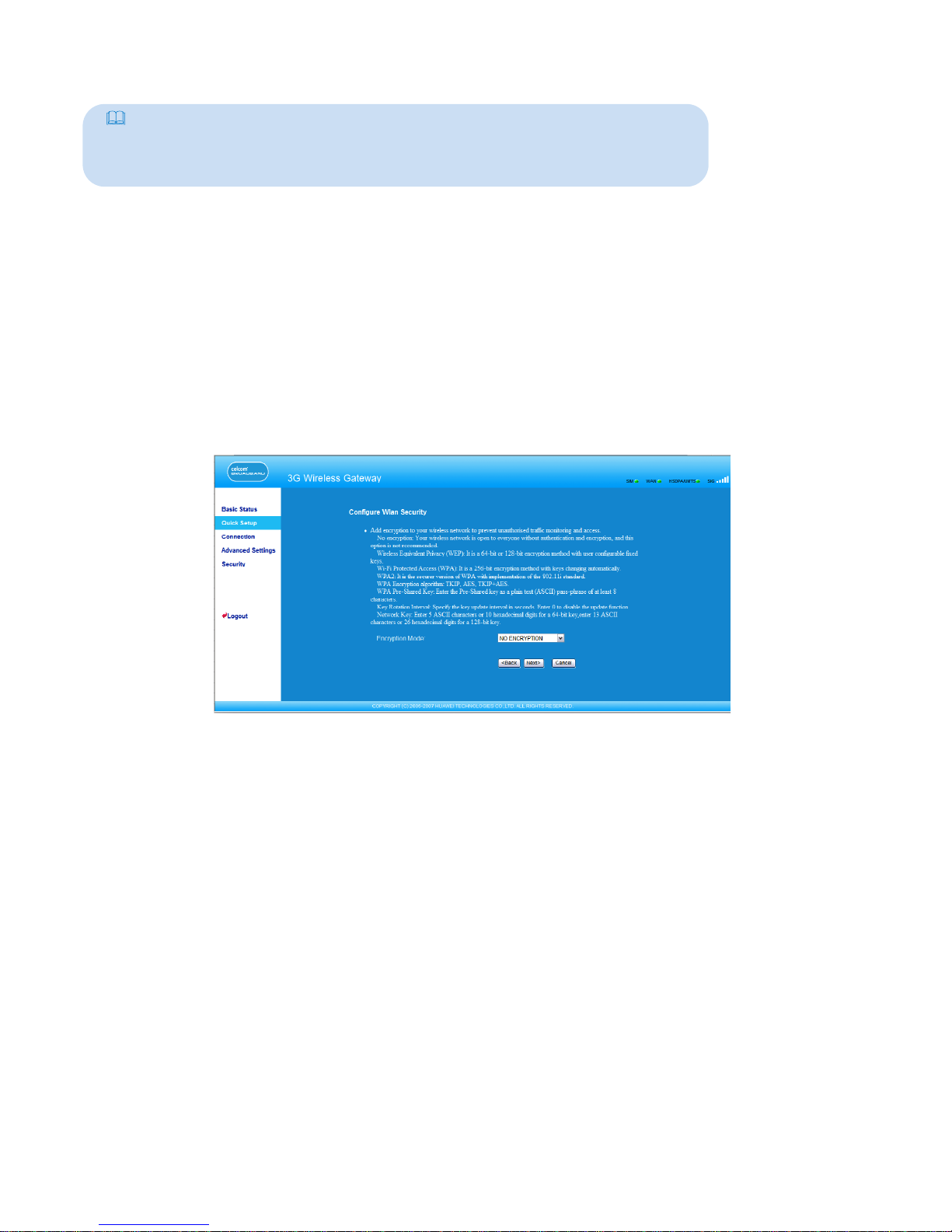
Conguring the WLAN Encryption Mode
To access the wireless network, you must set the wireless security key of your PC be consistent
with that of the wireless gateway.
No Encryption
For the convenience of the client accessing the WLAN, you can set the Encryption Mode
to NO ENCRYPTION when you set up a WLAN. In daily use, however, this option is not
recommended for the security of the WLAN.
WPA-PSK/WPA2-PSK
• WPA-PSK is a 256-bit data encryption method that can automatically change the key.
• WPA2-PSK is a more secure version of WPA-PSK, and it supports the IEEE 802.11 standard.
• WPA Encryption is algorithms for selecting the WPA data encryption. There are three
algorithms: TKIP, AES, and TKIP+AES.
• WPA Pre-Shared Key: You can enter 64-character hexadecimal value or 8-63-character
ASCII value as the key. The ASCII value contains all characters that can be entered
through the PC keyboard, and the hexadecimal value contains numbers of 0-9 and
characters of A-F. For example, you can enter the ASCII value of 1234abcde as the key.
• Network Key Rotation Interval: It is used to set how long a network key is dynamically
changed. By default, it is 0. To disable this function, you can set the value to 0 or Null.
11
Page 16
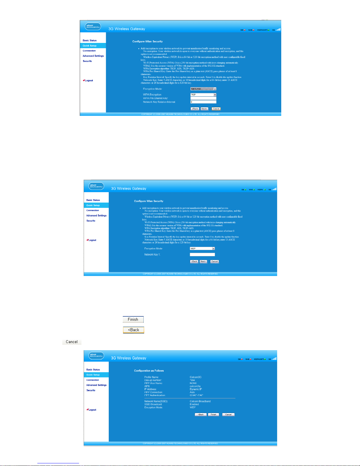
Validating Quick Setup
The last page of the wizard displays the all settings you have congured.
• To accept settings, click to submit the information.
• To make changes, click to return.
• Click to quit the settings.
WEP
Wireless Equivalent Privacy, a 64-bit or 128-bit data encryption method. The 128-bit WEP
encryption provides higher security level.
Network key 1: You can enter 5 ASCII characters or 10-character hexadecimal numeral
to form a 64-bit key. You can also enter 13 ASCII characters or 26-character hexadecimal
numeral to form a 128-bit key.
12
Page 17

Conguring Your Computer
5
In this part, take the Window XP operating system (OS) as an example to describe how to
congure your computer. For other OSs, the conguration may be different; thus, you need
to congure it according to the actual situation.
Wireless Conguration
The wireless conguration enables your PC connect to the E961 through the wireless network.
If you need only the Ethernet to connect your PC, you do not need to congure this.
Conguration Requirements
• To set up wireless network connection, your PC must have been congured with the
WLAN adapter that supports the IEEE 802.11 b/g protocol.
• If the encryption function is enabled, you need to ensure that all PCs connecting to the
E961 use the same key with the E961.
• For the use of WLAN adapter, refer to the WLAN adapter user guide provided by the
manufacturer.
• See “Conguring the WLAN Encryption Mode” for the encryption conguration.
• See “Conguring the WLAN Setting” for SSID parameters conguration.
Conguring the Wireless Network Connection
1. Select Start > Control Panel > Network Connections > Wireless Network Connection.
2. Click Show Wireless Networks to display the wireless network connection list.
3. Select the network connection that the SSID is consistent with that in the E961 WEB
conguration, and then click .
13
Page 18
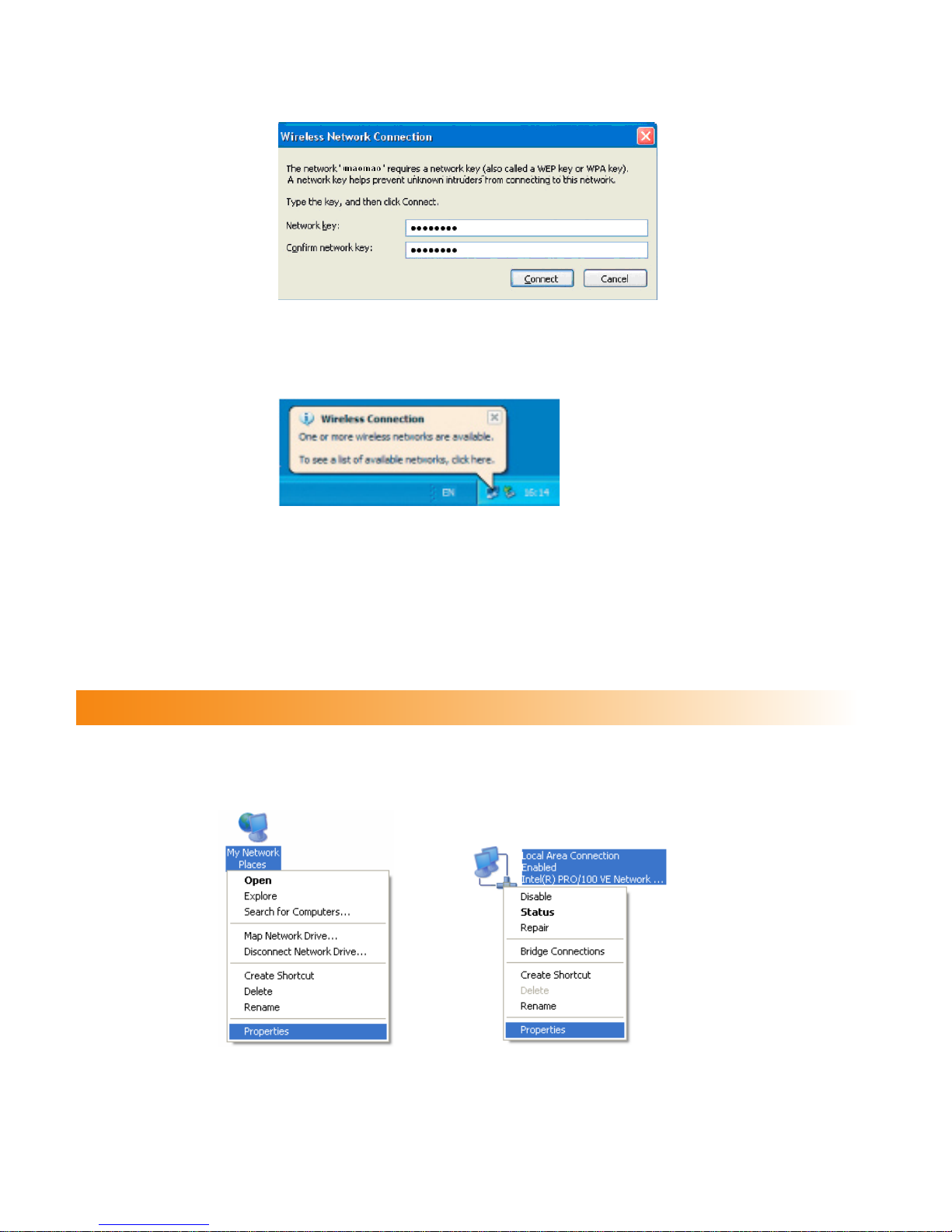
4. If the encryption parameter is set for the E961, the Wireless Network Connection dialog
box is displayed and requires the network key and conrmation. The value you entered
must be consistent with the WPA Pre-Shared Key or Network Key of the E961.
5. Wait for several minutes after you enter the correct network key. The wireless connection
icon displays in the status area in the lower right corner of the screen. Then, your PC can
automatically connect to the E961.
Conguring the PC Network
The recommended congurations of the gateway are as follows:
• Obtain an IP address automatically.
• Deselect Use a proxy server for your LAN.
Conguring the Network Connection
1. Select My Network Places > Properties > Local Area Connection.
2. Right-click the Local Area Connection icon and select Properties from the shortcut
menu.
14
Page 19
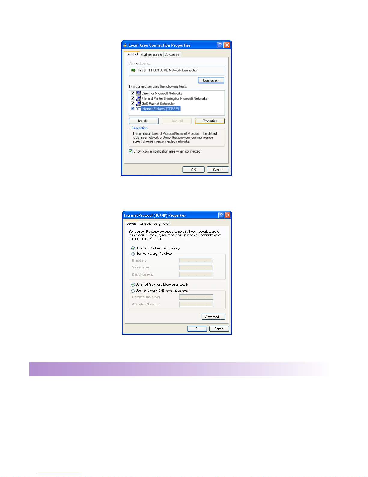
3. In the Local Area Connection Properties dialog box, select Internet Protocol (TCP/IP) in
the This connection uses the following items list box, and then click Properties.
4. Select Obtain an IP address automatically and Obtain DNS server address automatically
in the Internet Protocol (TCP/IP) Properties dialog box, and then click OK.
Disabling Proxy Settings
1. Start the IE browser, and then select Tools > Internet Options.
2. Select the Connections tab, and then click LAN Settings.
3. In the LAN Settings dialog box, deselect Use a proxy server for your LAN.
15
Page 20
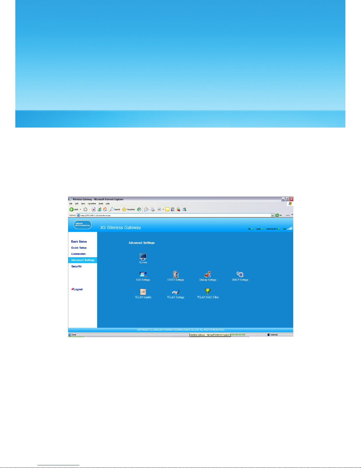
Describing Advanced Settings
6
In the Advanced Settings page, you can congure the basic attributes and advanced
parameters of the gateway, and perform routine maintenance and management to the
gateway.
In the operation navigation area, click Advanced Settings to access the page, as shown in
the following gure.
16
Page 21
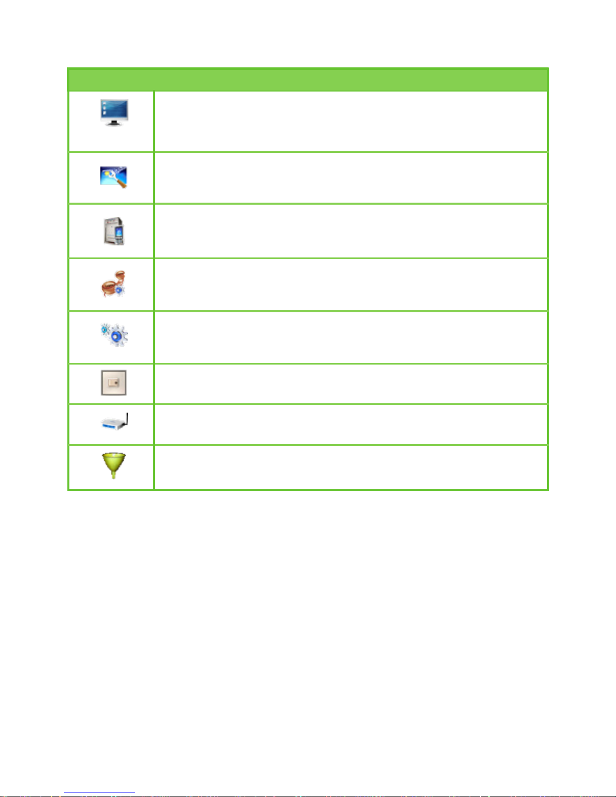
The following table describes shortcut icons.
Icon Description
Open the system management interface to modify the password,
upgrade software, restore the factory default, restart the device,
and view the version information.
Open the SIM card setting interface to manage the PIN code
operation.
Open the UMTS setting interface to congure the network search
mode and band.
Open the dial-up setting interface to congure PPP dial-up
properties and manage the prole list.
Open the DHCP setting interface to choose the IP address
assignment mode.
Open the interface to enable or disable the WLAN.
Open the WLAN setting interface.
Open the MAC address lter setting window.
17
Page 22
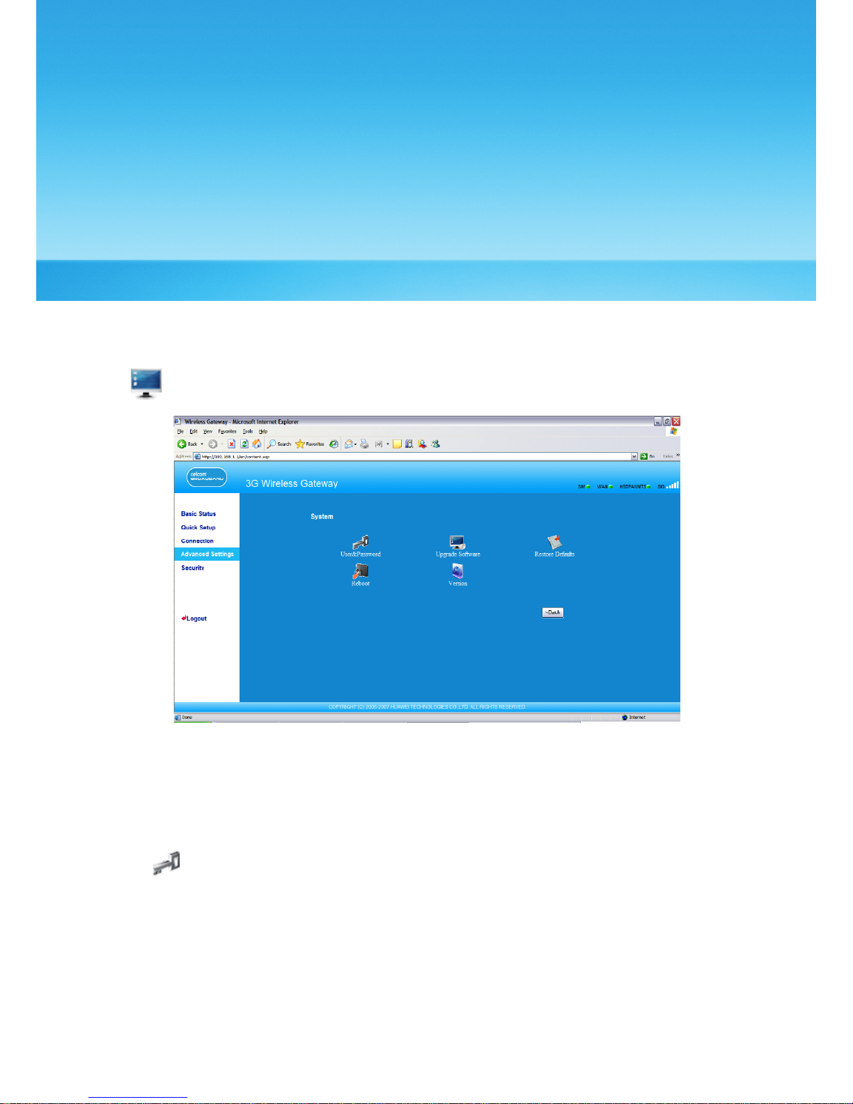
Managing the System
7
On the system management page, you can modify the password, upgrade the software,
restore factory defaults, restart the device, and view the version information.
Click to access the system management page, as shown in the following gure.
Modifying the Password
You can modify the login password to prevent unauthorized users from logging in to the
management page.
1. Click to open the Modify Password window.
18
Page 23
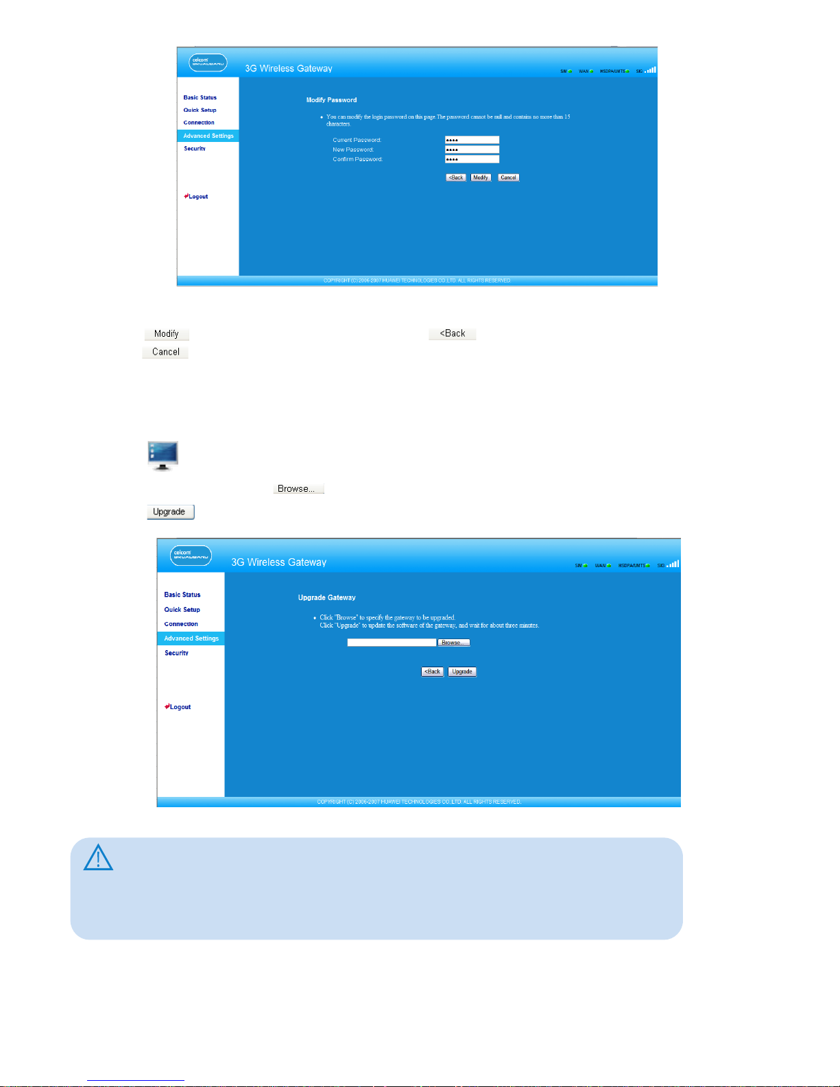
2. Enter the current password, and then enter the new password and conrm it.
3. Click to save the modication, click to return to the previous page, and
click to cancel the modication.
Upgrading the Gateway
1. Click to open the Upgrade Gateway page.
2. Enter the path or click to select the software image le to be updated.
3. Click to upgrade the system software.
Caution:
• After the system is upgraded, the system automatically restarts. The whole process
takes two to three minutes.
• The software programs for upgrading must come from the ofcial website of
Huawei or the ofcial website of the carrier.
• The system upgrading does not change the conguration of the client.
19
Page 24
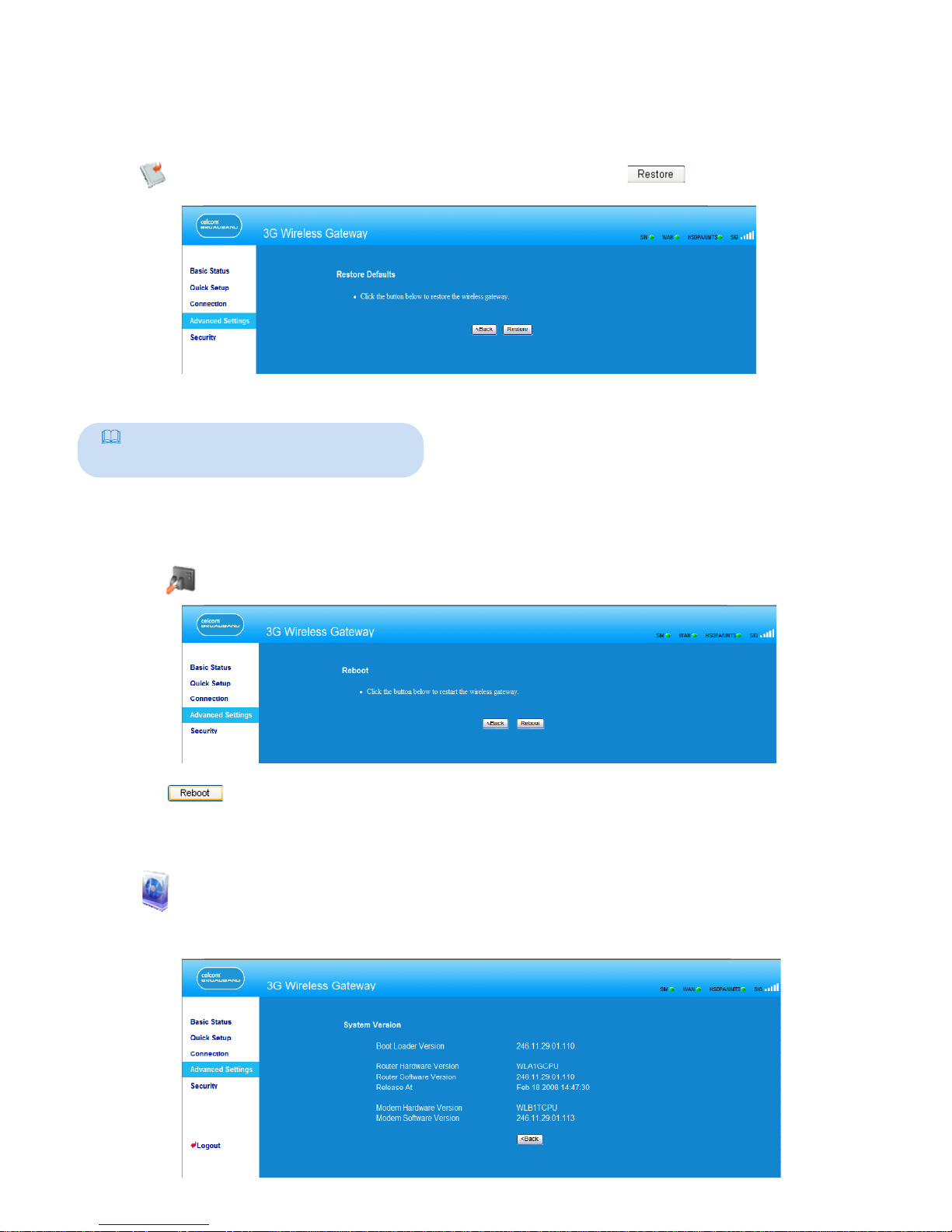
Restoring Factory Defaults
If you need to reconstruct the network or you forget the changes of some parameters,
you can choose to restore factory defaults and reconfigure the gateway.
Click to open the Restore Defaults window, and then click .
Note:
After this operation, all configurations
restore to the defaults.
Restarting the Device
1. Click to open the Reboot window.
2. Click to restart the gateway.
Viewing the Version Information
Click to display the System Version page. You can view the hardware version,
software version, release time, and the hardware version and software version of the
wireless module, as shown in the following figure.
20
Page 25
Conguring SIM Card Settings
8
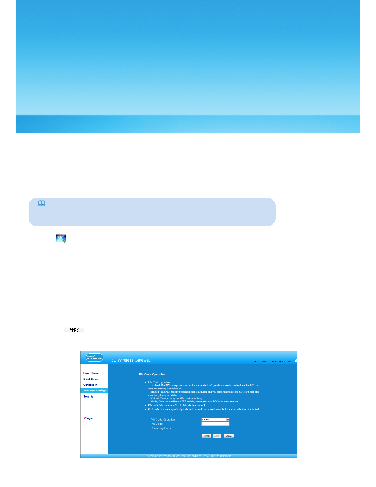
You can manage the PIN code on the SIM card settings window, including the following
operations:
• Enabling the PIN code
• Disabling the PIN code
• Moding the PIN code
• Unlocking the PIN code
Note:
• If you enter the wrong PIN code for three successive times, the PIN code is
locked. You need to enter the PUK code to unlock it.
• The PIN code must be 4–8 numerals, and letters are not allowed.
Click to open the SIM card setting window.
Enabling or Disabling the PIN Code
If the PIN code protection is enabled, you need to validate the PIN code each time when
you restart the gateway and log in to the management page; if the PIN code protection is
disabled, you do not need to validate the PIN code.
1. Select enable/disable in the PIN Code Operation list box.
2. Enter the correct PIN code.
3. Click .
4. If the PIN code is wrong, the system prompts you to reset it.
21
Page 26
Unlocking the PIN Code
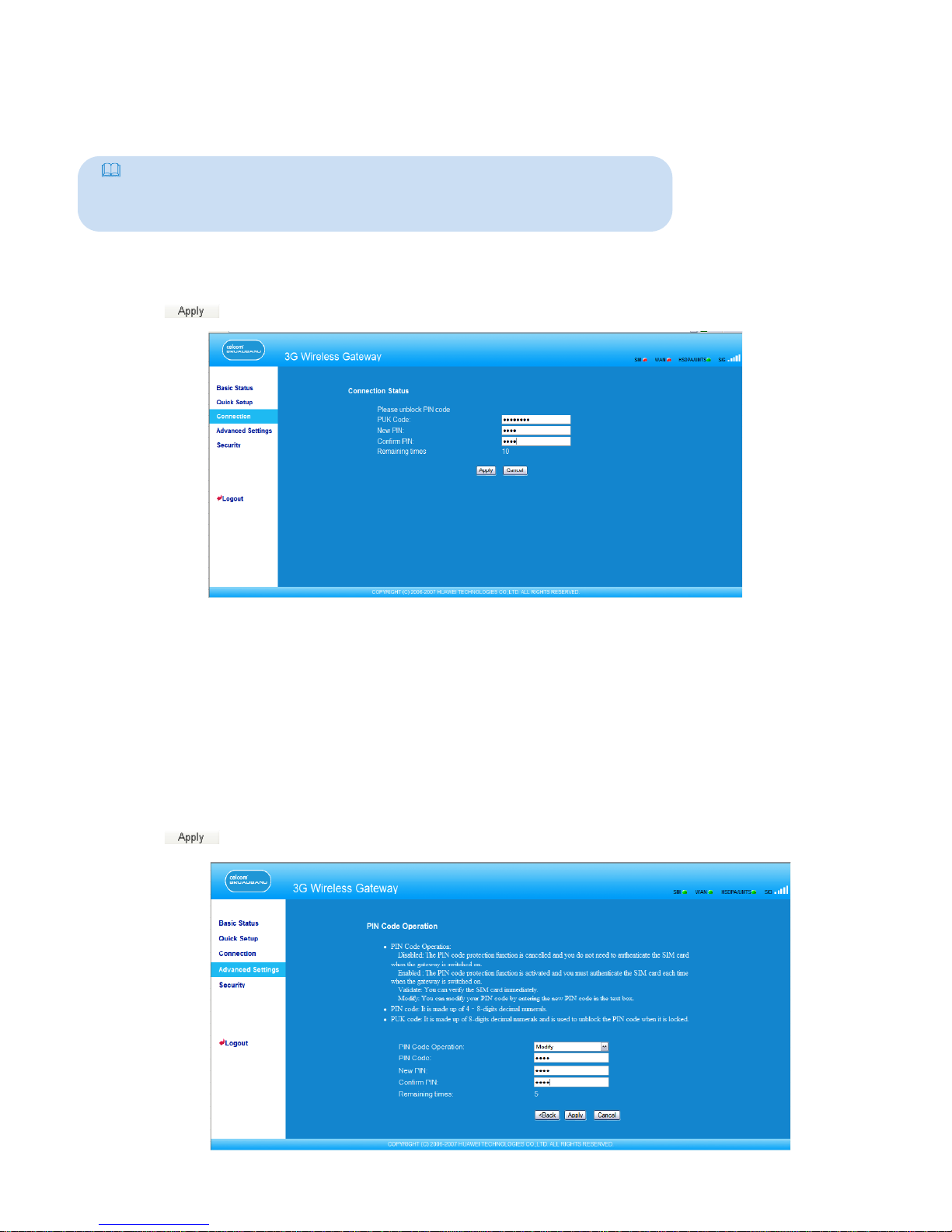
If the PIN code is locked, you need to enter correct PUK code and set the new PIN code to
unlock it.
Note:
• If you forgot the PUK code, consult your carrier.
• If you enter the wrong PUK code for successive 10 times, the SIM card is
locked. You need to consult your carrier to unlock the SIM card.
1. Enter the correct PUK code.
2. Enter the new PIN code and conrm it.
3. Click to submit the setting.
Modifying the PIN Code
When the PIN code protection is enabled, you can reset the PIN code.
1. Select modify in the PIN Code Operation list box.
2. Enter the current PIN code.
3. Enter the new PIN code and conrm it.
4. Click to submit the setting.
22
Page 27
Conguring UMTS Settings
9
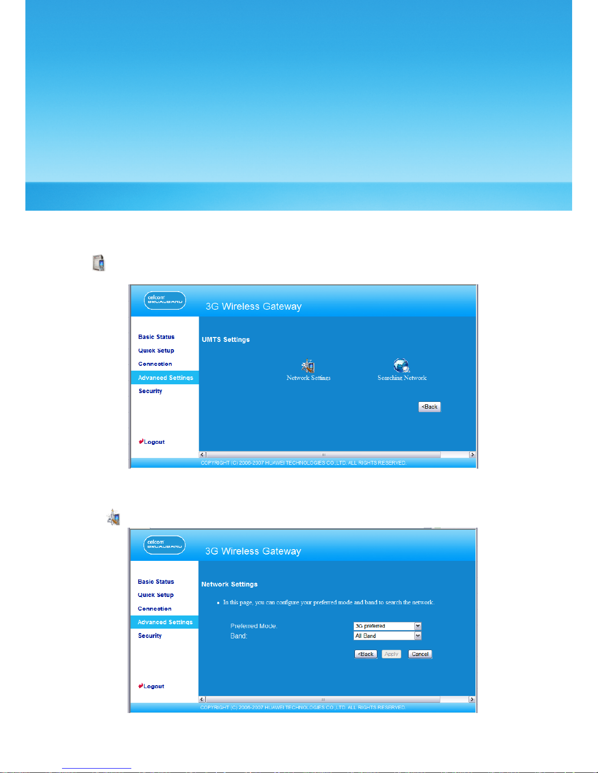
On the UMTS settings window, you can set the priority of connection modes and bands in
searching a network.
Click to open the UMTS Settings window, as shown in the following gure.
Choose the Preferred Mode and Band
1. Click to open the Network Settings window.
2. Select the preference of connection mode in the Preferred Mode list box. The following
table shows the details of connection modes.
23
Page 28
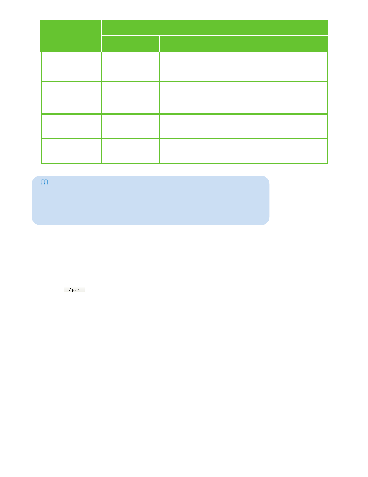
Network
Mode
3G preferred
GPRS preferred
3G only
GPRS only
Other
The E961 automatically selects the data service
mode based on the network signal strength. The
high-speed data service mode is preferred.
The E961 automatically selects the data service
mode based on the network signal strength. The
low-speed data service mode is preferred.
The E961 works only in high-speed data service
mode.
The E961 works only in low-speed data service
mode.
Performance
Maximum rate:
7.2 Mbit/s
Maximum rate:
236 Kbit/s
Maximum rate:
7.2 Mbit/s
Maximum rate:
236 Kbit/s
Description
Note:
• If the carrier provides only the GPRS service and the Preferred Mode is
congured as 3G only, you cannot access the Internet.
• If the carrier only provides only the HSDPA service and Preferred Mode is
congured as GPRS only, you cannot access the Internet.
• If the carrier provides neither the 3G nor GPRS service, you cannot access
the Internet regardless of the Preferred Mode.
3. Select the band to search the network in the Band list box. You can select from the
following:
• All Band
• GSM900/1800/UMTS2100
• GSM1900
• GSM850
4. Click to submit settings.
24
Page 29
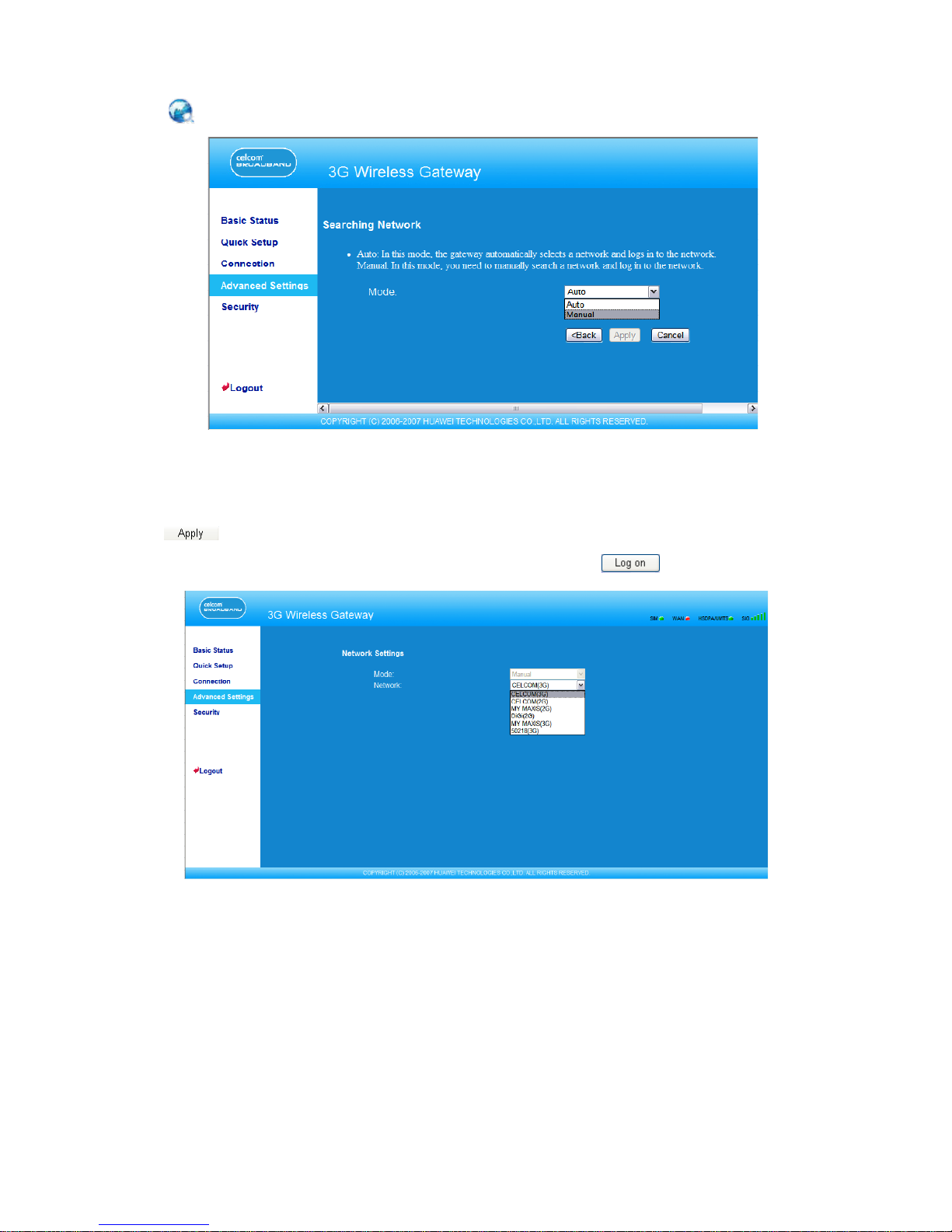
Conguring the Mode for Searching Network
1. Click to open the Searching Network window.
2. Select the mode for searching network.
• Auto: The gateway automatically searches the network and registers with it.
• Manual: You need to manually search the network and register with it.
3. Click to submit the setting.
4. In Manual mode, select the searched network and click .
25
Page 30
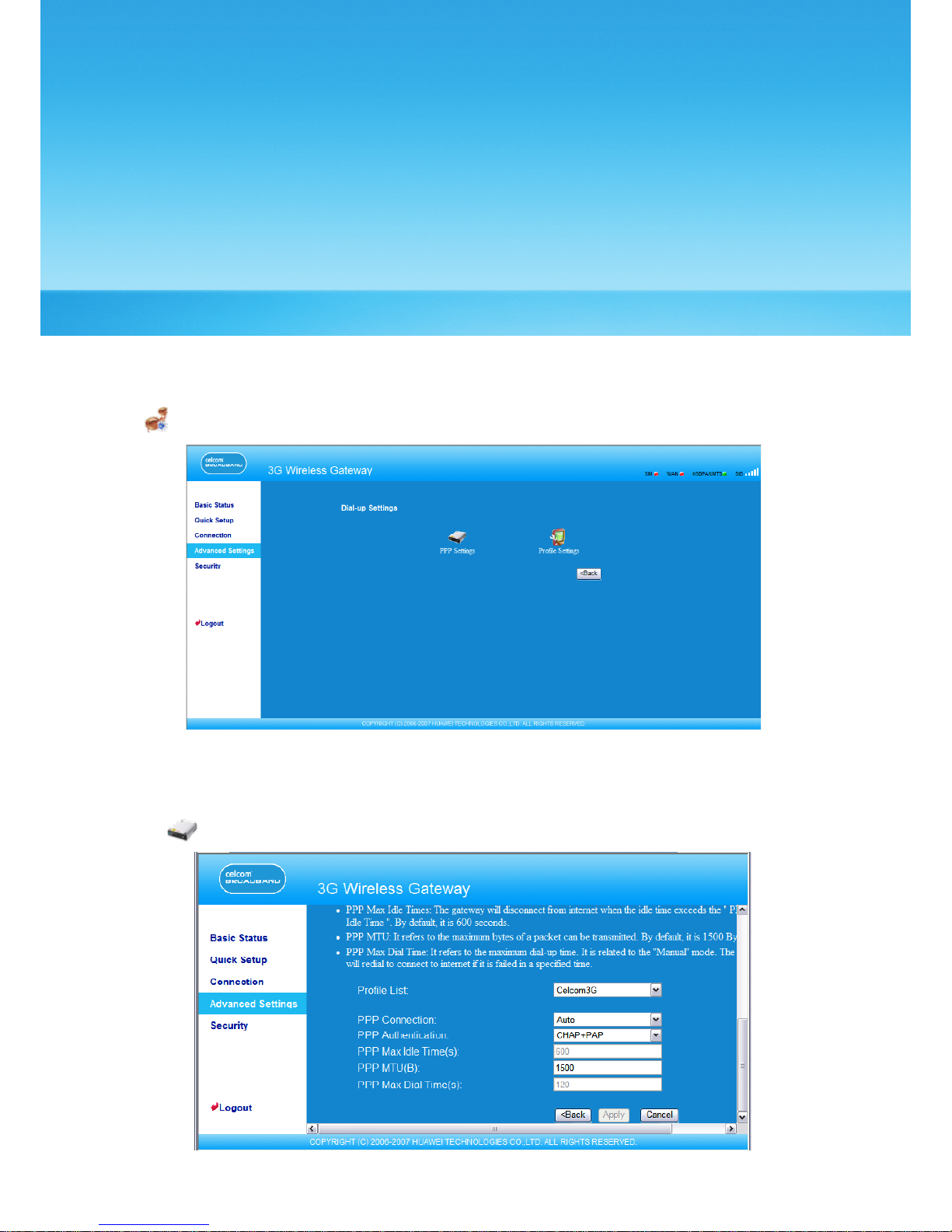
Conguring Dial-up Settings
10
In the Dial-Up Settings window, you can congure PPP settings and manage prole
settings.
Click to open the Dial-Up Settings window, as shown in the following gure.
Conguring PPP Settings
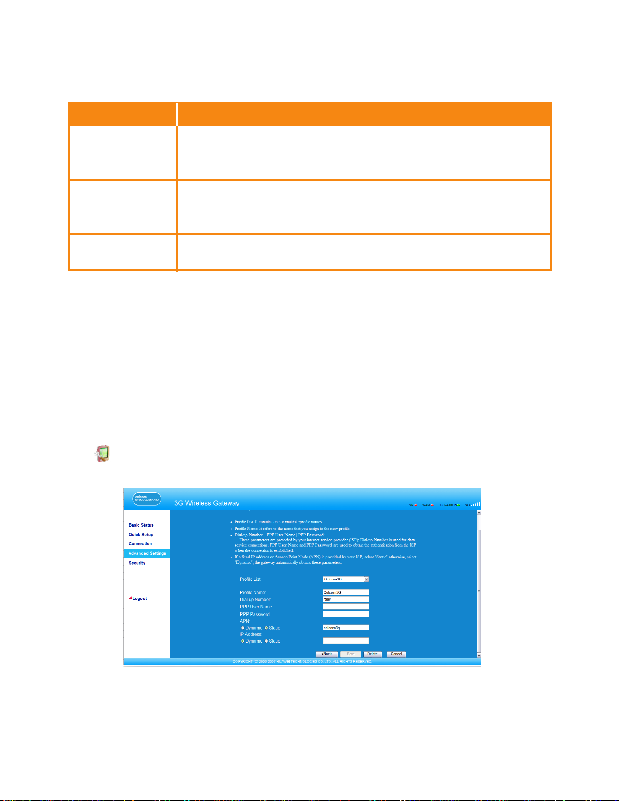
1. Click to open the PPP Settings window, as shown in the following gure.
26
Page 31
Dial-up Mode
Auto
On Demand
Manual
Description
After the gateway is switched on, it automatically connects
to the Internet and will not disconnect regardless of the data
transmission.
The gateway automatically connects to the Internet
when there is data transmission. It automatically closes the
connection when there is no data transmission.
Manual dial-up.
2. Enter the correct parameters.
• Prole List: Select a prole from the established dial-up connection list. If the drop-
down list is null, you need to create a prole list.
• PPP Connection: Select the dial-up connection mode.
• PPP Max Idle Time: The duration of the idle PPP connection. In On Demand mode, if
there is no data transmission beyond the duration, the PPP connection automatically
closes.
• PPP MTU: The MTU of the PPP data transmission. It is used to set the maximum number of
bytes encapsulated in a single data frame.
• PPP Max Dial Time: Set the maximum waiting time when connecting to the Internet.
Managing the Prole List
Click to open the Prole settings window and you can create, edit, save, and delete
a dial-up connection list.
27
Page 32
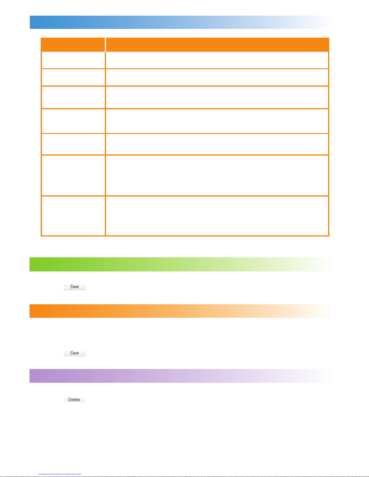
Interface Description
Parameter
Prole List
Prole Name
Dial-up Number
PPP User Name
PPP Password
APN
IP Address
Description
Include all created prole names.
Enter the name of the selected or created prole.
Enter the character string for PPP dial-up number. It is provided
by the network carrier.
The user name used in PPP communication. It is provided by
the network carrier.
The password used in PPP communication. It is provided by the
network carrier.
Select the mode for obtaining the APN:
• Dynamic: The network dynamically assigns the APN.
• Static: Manually enter the APN provided by the network
carrier.
Select the mode for assigning IP addresses:
• Dynamic: The network dynamically assigns the IP address.
• Static: Manually enter the IP address provided by the
network carrier.
Creating a Prole
1. Enter the prole information in the text box based on prompts.
2. Click to save the new prole.
Modifying a Prole
1. Select a prole to be modied in the Prole List drop-down list. Relevant information is
displayed in the corresponding text box.
2. Enter the prole information.
3. Click to save the modied prole.
Deleting a Prole
1. Select a prole to be deleted in the Prole List drop-down list.
2. Click to delete the selected prole.
28
Page 33
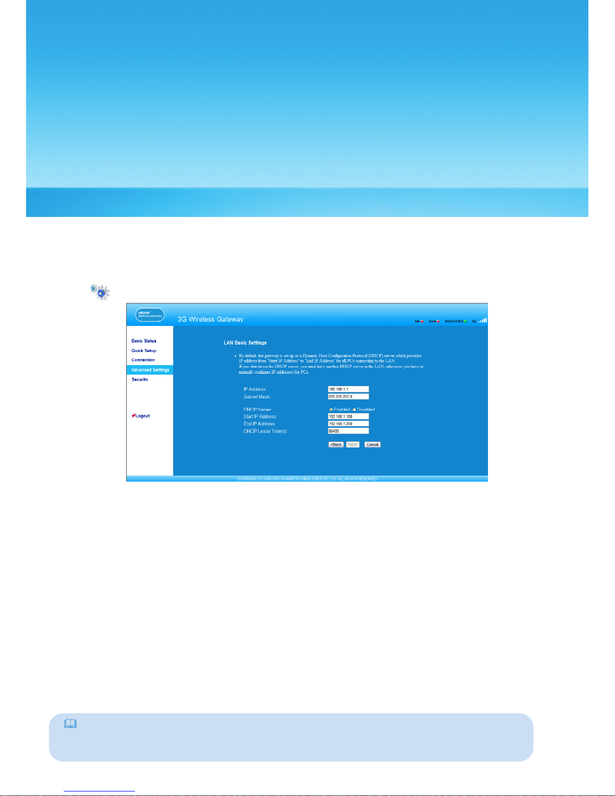
Assigning IP Addresses
11
In the LAN Basic Settings page, you can set the mode for assigning IP addresses in a LAN.
DHCP automatically assigns IP addresses to the network
devices. If you are using the DHCP
server, you need to do the following congurations on t
he PC connecting with the
gateway. For details, refer to “Conguring the PC Network.”
Click to open the LAN Basic Settings page.
• IP Address: The default IP address of the gateway is 192.168.1.1.
• Subnet Mask: The combination of the subnet mask and IP address enables the exible
subnetting. By default, the subnet mask is 255.255.255.0.
• DHCP Server: It is used to assign IP addresses dynamically. If the DHCP server is Enabled,
it can automatically assign IP addresses for PCs. It is recommended to select Disabled for
the DHCP server.
• Start IP Address & End IP Address: It is used to dene the IP address range that the host can
use during the IP address assignment. For example, in the network segment 192.168.1.0/24,
the default IP address of the E961 is 192.168.1.1. The host IP address can range from
192.168.1.2 to 192.168.1.254. The minimum range is a single IP address.
• DHCP Lease Time: The DHCP server automatically assigns an IP address to each device
connected to the network. When the leased time expires, the DHCP server checks
whether the device is connected to the network. If the device is disconnected from
the network, the server assigns the IP address to another device. Thus, the IP address is
not wasted.
Note:
• The Start IP Address must be smaller than or equal to the End IP Address.
• If the DHCP Server is Enabled, the congurations of Start IP Address, End IP address, and DHCP
Lease Time are valid; otherwise, you cannot congure them.
29
Page 34
Conguring the WLAN
12
Enabling or Disabling the WLAN
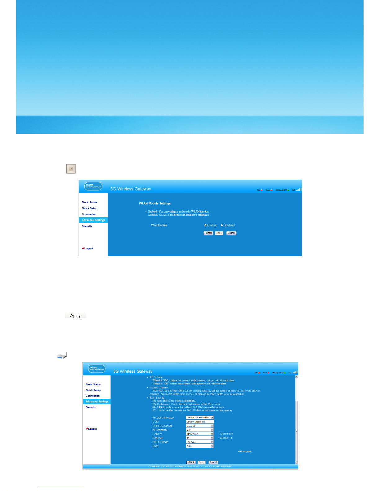
1. Click to open the WLAN Module Settings window, as shown in the following gure.
2. Enable or disable the WLAN module.
• Enable: Enable the WLAN module. You can use the WLAN function and congure
relevant parameters.
• Disable: Disable the WLAN module. You cannot use the WLAN function and congure
relevant parameters.
3. Click to submit the setting.
Conguring WLAN Settings
Click to open the WLAN Settings window, as shown in the following gure.
30
Page 35
Selecting Interface IDs
Wireless Interface: It refers to the SSID and MAC address, and is used to identify the wireless
gateway.
SSID
SSID: The service set identier (SSID) is used to identify a WLAN. A wireless terminal (such as
a PC) and the wireless gateway can perform normal data communication only when they
have the same SSIDs. To ensure the WLAN security, do not use the default SSID. You can
enter a character string as the SSID, such as MyHome.
Enabling or Disabling the SSID Broadcast
• Enabled: Enable the SSID broadcast. The E961 broadcasts the SSID of the WLAN, and
users can easily access the WLAN. Unauthorized users, however, can also easily access
the WLAN.
• Disabled: Disable the SSID broadcast. The E961 does not broadcast the SSID of the WLAN.
Before accessing the WLAN, the user must obtain the SSID of the WLAN. Thus, the WLAN
security is improved.
Enabling or Disabling the AP Isolation
• On: The terminals (PCs) connecting to the gateway through the WLAN cannot access
each other.
• Off: The terminals (PCs) connecting to the gateway through the WLAN can access each
other.
Selecting the WLAN Channel
• Country: It is used to identify the country. Different countries have different standards on
channel usage.
• Channel: It refers to the channel that the gateway works with. According to the IEEE802.11
standard, the working frequency for the WLAN adopting the Direct Sequence Spread
Spectrum (DSSS) technology ranges from 2.4 GHz to 2.4835 GHz. Each channel occupies
a neighboring 22 MHz frequency band. The available channels vary with the selected
country. If you do not know which channel to select, select Auto and the gateway can
automatically search for the channel.
Conguring the 802.11 Mode
There are four available modes, as shown in the following table.
Mode
54g Auto
54g Performance
54g LRS
802.11b Only
Description
The WLAN has the best compatibility in this mode.
The WLAN has the best performance in this mode.
If the E961 has difculties in communicating with devices
conforming to the IEEE 802.11b standards, select this mode.
The E961 can only work in the low performance 802.11b
standard network mode.
31
Page 36
Conguring the Transmission Rate
1. Select Auto, the E961 automatically searches the transmission rate. The maximum WLAN
transmission rate supported by the gateway is 54 Mbit/s.
2. Click to submit the setting.
3. Click Advanced to congure the advanced WLAN setting.
Advanced WLAN Settings
You can congure the security and Network Bridge.
Conguring Security Key
A security key can protect your WLAN from illegal data attacking. The security key of your
wireless gateway must be consistent with that of the PC.
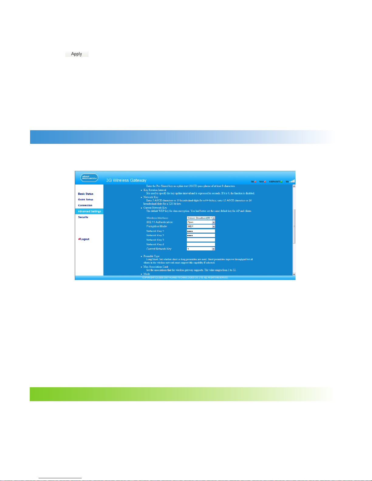
Conguring the 802.11 Authentication
• Open: Open system authentication. A user accessing the WLAN can choose WEP,
WPA-PSK, or WPA2-PSK key to pass the authentication or choose No encrytion to skip the
authentication.
• Shared: Shared key authentication. It can use only WEP. The user accessing the WLAN
must use the WEP to authenticate.
Conguring the Encryption Mode
There are four encryption modes: No Encryption, WPA-PSK, WPA2-PSK, and WEP. For details,
refer to “Conguring the WLAN Encryption Mode.”
Conguring Access Attributes of the Client
As shown in the following gure, you can set the Preamble Type, Max Associations Limit,
Mode, and enable or disable the peer MAC address through the Bridge Restriction.
32
Page 37
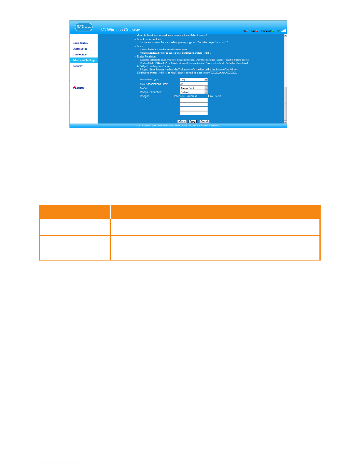
• Preamble Type: It has two options: Long and Short. In the case that the client (PC) supports
the Short type, the WLAN can have a better performance if it is Short.
• MAX Associations Limit: It refers to the maximum number of connections. It is used to set
the maximum number of concurrent WLAN users on the gateway. A maximum of 32
clients can connect with the gateway in wireless mode.
• Mode: It refers to the WLAN accessing mode. The gateway can work in two modes, as
shown in the following table. The default value is Access Point.
Mode
Wireless Bridge
Access Point
Description
It is used to connect two or more access points.
The access points meeting the IEEE 802.11b/g standard or
the wireless terminals can connect the wireless gateway.
• Bridge Restriction: It refers to the limitation to the peer MAC addresses. When it is Disabled,
the E961 can access all the remote bridges; when it is Enabled, the E961 can only access
the remote bridges that the addresses are in the address list.
• Bridges: It refers to the physical address of the remote peer bridge. The gateway supports
the point-to-multipoint (PTM) bridge mode, and a wireless gateway can connect four
remote peer bridges at the same time.
• Peer MAC Address: It refers to the physical address list of the remote peer bridges. It
contains a maximum of four physical addresses.
• Link Status: Up shows the successful connection and Down shows the failed
connection.
33
Page 38
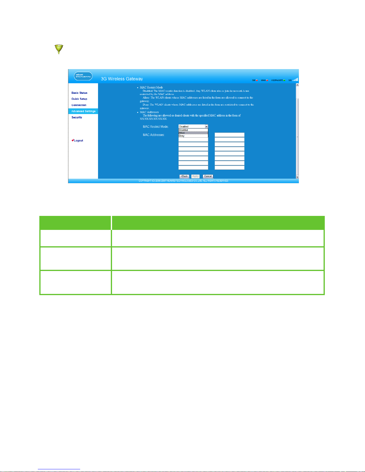
Conguring the MAC Filter
Click to open the WLAN MAC Filter Settings window. You can control and manage the
clients accessing the WLAN, and improve the WLAN security performance.
MAC Restrict Mode
The following table lists the MAC address lter modes:
Value
Disabled
Allow
Deny
Description
The MAC address lter function is disabled.
The clients with addresses in the MAC Address list are
allowed to connect with the gateway through the WLAN.
The clients with addresses in the MAC Address list are not
allowed to connect with the gateway through the WLAN.
MAC Addresses
Enter MAC addresses in the list. The gateway can perform access control over the clients
that MAC addresses are in the list. The list can contain a maximum of 16 MAC addresses.
34
Page 39
13
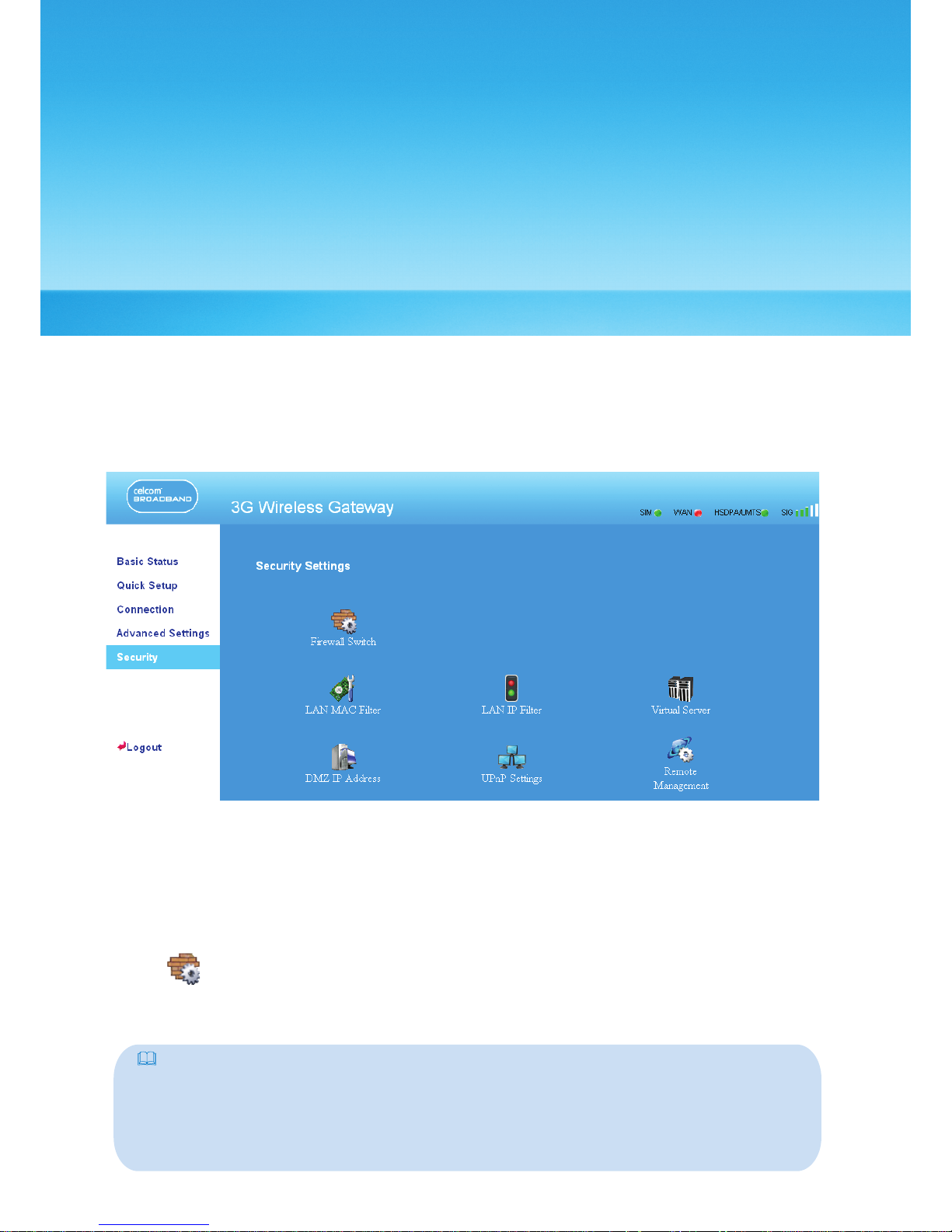
Security Settings
On the Security Settings page, you can configure the advanced security settings.
Click Security to access the security settings page, as shown in the following figure.
Firewall Switch
Your gateway has a true firewall that controls the incoming and outgoing data flow
and protects your computer from illegal intrusion.
1. Click to access the Firewall Switch window.
35
2.
Select the Enable the firewall (main switch of the firewall) check box to enable
the firewall.
Note:
• Only when the Enable the firewall check box is selected, the other functions such as the
IP address filter function, the MAC address filter function, and the WAN port ping function
are available.
•
When the Enable LAN MAC address filter check box is selected, the default filter rules
are available.
Page 40
3. Select other options as required, and then click
LAN MAC Filter
Your gateway supports MAC filtering based on a list of either denied or allowed computers.
A common method to restricting network access is to specify the Media Access Control
(MAC) address.
To locate the MAC address in Windows, choose Start > Run, and then enter cmd.
The command window is displayed, enter ipconfig /all, and then press Enter.
The MAC address is displayed as the Physical Address.
1. Click to access the LAN MAC Filter window.
2. Select MAC Filter Mode.
LAN IP Filter
You can configure the gateway to block specific IP addresses from accessing the LAN.
Click to access the IP Address Filter window.
36
.
Value
Disabled
Allow
Deny
Description
The MAC address filter function is disabled.
The clients with addresses in the MAC Address list are
allowed to connect with the gateway through the LAN.
The clients with addresses in the MAC Address list are not
allowed to connect with the gateway through the LAN.
3. Enter the MAC addresses of the clients and click
.
Adding an IP Address
1. Select the protocol and status.
2. Enter the IP address and corresponding port to be blocked from accessing the LAN.
3. Click to add the IP address to the table.
Modifying an IP Address
1. Click in the Modification column. The corresponding IP address filter is displayed.
2. Modify the contents as required.
3. Click .
Deleting an IP Address
Click in the Modification column. The corresponding IP address filter is deleted.
Page 41
Virtual Server
Your gateway supports virtual server to enable external computers to access WWW, FTP, or
other services provided by the LAN.
Click to access the Virtual Server page.
37
Adding a Virtual Server
Making an IP Filter Effective
1. Add a new IP address or select a record in the IP address filter table.
2. Select On for Status.
3. Click .
4. Click . The IP filter takes effect.
1. Select the protocol and status.
2. Enter values in the following textboxes:
Name: Enter a name to the service provided by the LAN.
WAN Port: Enter the WAN port of the LAN in which the computer provides services.
IP Address: Specify a computer in the LAN to provide services.
LAN Port: Enter the LAN port of the computer that provides services.
3. Click to add the virtual server to the table.
You can also add a virtual server by the following way:
1. Select a port form the Common Port list. The Protocol, Status, Name, WAN Port and LAN
Port will be set as default value. If required, you can modify them.
2. Input the IP Address.
3. Click to add the virtual server to the table.
•
•
•
•
Modifying a Virtual Server
1. Click in the Modification column. The corresponding virtual server is displayed.
2. Modify the contents as required.
3. Click .
Deleting a Virtual Server
Click in the Modification column. The corresponding virtual server is deleted.
Making an Virtual Server Effective
1. Add a virtual server or select a record in the virtual server table.
2. Select On for Status.
3. Click .
4. Click . The IP filter takes effect.
Page 42
DMZ Service
If your PC cannot run network applications through the device, you can set the computer
to access the Internet unlimitedly by configuring the IP address of the computer in the
demilitarized zone (DMZ).
However, the DMZ computer is not protected by the firewall. It is vulnerable to attack and
may also put other computers in the home network at risk.
1. Click .
2. Select Enabled /Disabled for DMZ Status to enable or disable the DMZ service.
3. Enter the local IP address of the computer that is specified as a DMZ host.
4. Click .
38
Note:
Only one computer can be specified as a DMZ host at a time.
UPnP Settings
The Universal Plug and Play (UPnP) service allows other network users to control your device’s
network features to realize the intelligent interconnection.
1. Click .
2. Select Enabled/Disabled for UPnP Status to enable or disable the UPnP service.
3. Click .
Remote Management
The remote web management allows the access and control of the device either from the
home network or from the Internet.
When you are on a trip, you can maintain your device through the remote web
management service. It also allows your ISP to help you solve the device problems from a
remote location.
1. Click .
2. Select Enabled or Disabled for Remote Status to enable or disable the service.
3. Enter the IP address that can access and control your device.
4. Click .
Page 43
Typical Networking Example
14
You can construct a small LAN through the WLAN interface or four Ethernet interfaces of
the gateway.
Your gateway also supports external hubs, Ethernet switches, or routers. To construct a
LAN with multiple PCs, you can extend the Ethernet interfaces through a hub or Ethernet
switch.
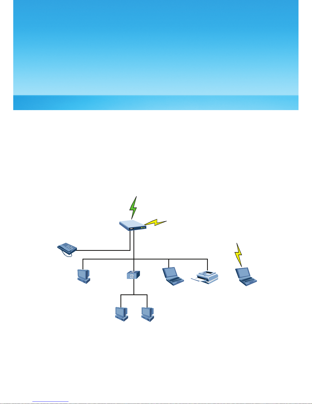
For example, the gateway constructs a small-sized LAN with multiple PCs in the SOHO to
access the Internet wirelessly, and the networking diagram is as follows:
DHCP
IP:192.168.1.107
R o u tin g /NA T
E9 60
PC3PC2
PC1
PrinterLaptop1 Laptop2
LAN Sw itch/
Router
IP:192.168.1.108
DHCP
IP:192.168.1.105
192.168.1.1/24
218.10.1.1
DHCP
IP:192.168.1.109
UP L INK (HS DP A )
WLAN
WLAN
Phone
Ethernet
RJ11
39
1
(HSDPA)
Switch/
Page 44

Troubleshooting
15
What if the Signal Strength Indicator is blinking in red?
1. Please ensure that the SIM card is inserted correctly.
2. If yes, please login to the Web Management Page (http://192.168.1.1) with the Admin
password and key in 1234 as the PIN code.
3. To permanently disable the PIN code prompt, kindly refer to Section 8: Enabling or
Disabling the PIN Code
The PC in a LAN mode cannot access Internet.
1. The power indicator is on, and the E961 is normally connected with the power adapter.
If the power indicator is off, you need to check whether the power is normally
connected.
2. If the signal strength indicator on the E961 panel is off, you need to check whether the
area is covered by WLAN.
3. If the area is covered by WLAN, you need to check whether the network mode is right.
See Chapter 9 “Configuring UMTS Settings” for information about network mode.
4. If the indicator of Ethernet interface blinks, the corresponding Ethernet interface is
normally connected. If the indicator is off, you need to check and ensure that the
corresponding Ethernet connection is normal.
5. You must configure the correct PPP user name and PPP password when you access
the internet through the E961. Check whether they are correct, and see “Configuring
PPP Profile Settings” for details.
6. If the DHCP service is disabled and the PC obtains the IP address dynamically, the PC also
cannot access the internet. You can change the mode to manually assign an IP address.
See “Configuring the PC Network.”
7. Check whether the driver of the network adapter is correctly installed.
8. If the preceding methods cannot solve the problem, please consult your service
provider.t.
1. If there are interferences or shields near the E961, you can adjust the position of the E961.
When the signal strength is strong, you can move to the next step.
2. Check and record the following data on the PC’s network adapter: SSID, WEP type, and
key.
3. Check and record the following data on the E961: SSID, WEP type, and key.
4. Compare the data, the SSID on the network adapter should be ANY or be the same
with that on the E961. The WEP type and key on the network adapter and E961 should be
identical. Otherwise, you need to change the data on the network adapter.
40
Page 45

Warnings and Precautions
16
Electronic Device
• Turn off your device near high-precision electronic devices. The wireless device may
affect the performance of these devices.
• Such devices include hearing aids, pacemakers, fire alarm systems, automatic gates, and
other automatic-control devices can be affected. If you are using an electronic medical
device, consult the device manufacturer to confirm whether the radio wave affects the
operation of this device.
Hospital
Pay attention to the following points in hospitals or health care facilities:
• Do not take your wireless device into the operating room (OR), intensive care unit (ICU),
or coronary care unit (CCU).
• Do not use your wireless device at places for medical treatment where wireless device
use is prohibited.
• When using your wireless device near someone who is suffering from a heart disease,
turn down the ring tone volume or vibration properly so that it does not affect the
person.
Traffic Safety
• Please observe local laws and regulations on wireless device use. Do not use your wireless
device while driving to avoid traffic accident.
• Secure the wireless device on its holder. Do not place the wireless device on the seat or
other places where it can get loose in a sudden stop or collision.
• Use the wireless device after the vehicle stops at a safe place.
• Do not place the wireless device over the air bag or in the air bag outspread area.
Otherwise, the wireless device may hurt you owing to the strong force when the air bag
inflates.
• Observe the rules and regulations of airline companies. In areas where wireless
device use is prohibited, turn off the wireless device. Otherwise, the radio signal of the
wireless device may disturb the plane control signals. Turn off your wireless device before
boarding an aircraft.
Storage Environment
• Do not place magnetic storage media such as magnetic cards and floppy disks near
the wireless device. Radiation from the wireless device may erase the information stored
on them.
41
Page 46

• Do not put your wireless device or other accessories in containers with strong
magnetic eld, such as an induction cooker and a microwave oven. Otherwise, circuit
failure, re, or explosion may occur.
• Do not leave your wireless device or charger in a very hot or cold place.
Otherwise, malfunction of the products, re, or explosion may occur.
• Do not place sharp metal objects such as pins near the earpiece. The earpiece may
attract these objects and hurt you when you are using the wireless device.
• Do not subject your wireless device and charger to serious collision or shock.
Otherwise, battery leakage, wireless device malfunction, overheat, re, or explosion may
occur.
• Do not put your wireless device in the back pocket of your trousers or skirt to avoid
wireless device damage while seated.
Children Safety
• Put your wireless device and charger in places beyond the reach of children.
Do not allow children to use the wireless device or charger without guidance.
• Do not allow children to put the charger in mouth, for electrolyte in the charger is
dangerous.
• Do not allow children to touch the small ttings. Otherwise, suffocation or gullet jam can
be caused if children swallow the small ttings.
Operating Environment
• The wireless device and charger are not water-resistant. Keep them dry. Protect
the wireless device, battery and charge from water or vapor. Do not touch the wireless
device with a wet hand. Otherwise, short-circuit and malfunction of the product or
electric shock may occur.
• Do not use the wireless device in dusty, damp and dirty places or places with magnetic
eld. Otherwise, malfunction of the circuit may occur.
• Do not turn on or off the wireless device when it is near your ears to avoid negative
impact on your health.
• When carrying or using the wireless device, keep the antenna at least 1.5
centimeters away from your body, to avoid negative impact on your health caused by
radio frequency leakage.
• If you feel uncomfortable (such as falling sick or qualm) after playing games on your
wireless device for a long time, please go to see a doctor immediately.
• On a thunder stormy day, do not use your wireless device outdoors or when it is being
charged.
• Do not touch the antenna when a call is going on. Touching the antenna may affect call
quality and cause the wireless device to operate with more power. As a result, the talk
time and standby time are shortened.
• The wireless device may interfere with nearby TV sets, radios and PCs.
• In accordance with international standards for radio frequency and radiation, use
wireless device accessories approved by the manufacturer only.
Cleaning and Maintenance
• Before you clean or maintain the wireless device, turn off it and disconnect it from the
charger. Otherwise, electric shock or short-circuit of the battery or charger may occur.
• Do not use any chemical detergent, powder, or other chemical agent (such as alcohol
and benzene) to clean the device and the charge. Otherwise, part damage or a re
can be caused. You can clean the device and the charger with a piece of soft antistatic
cloth that is a little wet.
• Do not scratch the shell of the wireless device. Otherwise, the shed coating may cause
skin allergy. Once it happens, stop using the device at once and go to see a doctor.
• If the wireless device or any of its ttings does not work, turn to the local authorize service
center for help.
42
Page 47

Abbreviations
17
3G
A
AC
ARP
AP
APN
C
CDMA
D
DHCP
DNS
DL
E
EDGE
G
GSM
GPRS
GGSN
H
HSPA
HSDPA
HSUPA
HLR
I
IP
ICMP
The Third Generation
Alternating Current
Address Resolution Protocol
Access Point
Access Point Name
Code Division Multiple Access
Dynamic Host Configuration Protocol
Domain Name Server
down link, downlink
Enhanced Data rates for GSM Evolution
Global System for Mobile communications
General Packet Radio Service
Gateway GPRS Support Node
High Speed Packet Access
High Speed Downlink Packet Access
High Speed Uplink Packet Access
Home Location Register
Internet Protocol
Internet Control Message Protocol
43
Page 48

L
LAN
LED
L2TP
M
MSC
N
NAT
P
PCS
PSTN
POTS
PPTP
R
RTT
S
SOHO
SCP
SGSN
SDRAM
T
TKIP
U
UMTS
UL
V
VLR
VPN
W
WAN
WLAN
WCDMA
WI-FI
Local Area Network
Light Emitting Diode
Layer 2 Tunneling Protocol
Mobile Switching Center
Network Address Translation
Personal Communication Systems
Public Switched Telephone Network
Plain Old Telephone Service
Point to Point Tunneling Protocol
Radio Transmission Technology
Small Ofce Home Ofce
Service Control Point
Serving GPRS Support Node
Synchronous Dynamic Random Access Memory
Temporal Key Integrity Protocol
Universal Mobile Telecommunications System
up link, uplink
Visitor Location Register
Virtual Private Network
Wide Area Network
Wireless Local Area Network
Wideband CDMA
Wireless Fidelity
44
 Loading...