

CEL ZICM357SP0-1, ZICM357SP2-1 Datasheet
DATA SHEET
ect
™
MeshConnect™ EM357 Mini Modules
ZICM357SP0-1, ZICM357SP2-1
EmberTM EM357 Transceiver Based Modules
Integrated Transceiver Modules for ZigBee/IEEE 802.15.4
Development Kit available: ZICM-EM35X-DEV-KIT-2
DESCRIPTION
CEL’s MeshConnect™ EM357 Mini Modules combine high
performance RF solutions with the market's premier ZigBee
®
stack. Available in low and high output power options
(+8dBm and +20dBm), these modules can accommodate
variable range and performance requirements. The tiny
module footprint makes them suitable for a wide range
of ZigBee applications. The MeshConnect EM357 Mini
Modules are certied and qualied, enabling customers to
accelerate time to market by greatly reducing the design
and certication phases of development.
CEL's MeshConnect EM357 Mini Modules (ZICM357SP0,
ZICM357SP2) are based on the Ember EM357 Zigbee
compliant SOC radio IC. The IC is a single-chip solution,
compliant with ZigBee specications and IEEE 802.15.4,
a complete wireless solution for all ZigBee applications.
The IC consists of an RF transceiver with the baseband
modem, a hardwired MAC and an embedded 32-bit ARM®
Cortex™-M3 microcontroller with internal RAM (12kB) and
Flash (192kB) memory. The device provides numerous
general-purpose I/O pins and peripheral functions such as
timers and UARTs.
ORDERING INFORMATION
MeshConn
ZICM357SP0 ZICM357SP2
+8dBm +20dBm
-100dBm -103dBm
Link Budget:
+108dB +123dB
FEATURES
• High RF Performance:
Up to 123 dB RF Link Budget
RX Sensitivity:
-100 dBm (ZICM357SP0)
-103 dBm (ZICM357SP2)
• Data Rate: 250 kbps
• Advanced Cortex-M3 Processor
•
Advanced Power Management
• 16 RF Channels
• Industry's Premier ZigBee Pro
Stack: EmberZNet PRO™
APPLICATIONS
• Smart Energy / Grid Markets
Thermostats
In-Home-Displays
Smart Plugs
•
Building Automation and
Control
• Lighting: Fixture and Control
Tx:
Rx:
EM357 Mini Modules
• 192 kB FLASH
• 12 kB SRAM
• 32-bit ARM® Cortex™-M3
• Up to 23 GPIO Pins
• SPI (Master/Slave), TWI, UART
• Timers, Serial Wire/JTAG Interface
• 5-channel 14-bit ADC
• Mini Footprint: (23.9mm x 16.6mm)
0.940" x 0.655"
• Antenna Options:
1) Integrated PCB Trace Antenna
or
2) RF Port for External Antenna
• Supports Mesh Networks
• AES Encryption
• FCC, CE and IC Certifications
• ROHS Compliant
• Solar Inverter and Control
• Home Automation and Control
Energy Management
Security Devices
HVAC Control
•
General ZigBee Wireless Sensor
Networking
Part Number Order Number Description Min./Multiple
ZICM357SP0-1 +8 dBm Output Power, PCB Trace antenna 330 / 330
MeshConnect™
EM357 Mini Modules
MeshConnect™ EM357
Development Kit
The information in this document is subject to change without notice.
Document No: 0011-00-07-00-000 (Issue E)
Date Published: June 20, 2013
ZICM357SP0-1C +8 dBm Output Power, with Castellation pin for external antenna 330 / 330
ZICM357SP2-1 +20 dBm Output Power, PCB Trace antenna 330 / 330
ZICM357SP2-1C +20 dBm Output Power, with Castellation pin for external antenna 330 / 330
ZICM-EM35X-DEV-KIT-2
MeshConnect EM35x Ember Companion Kit for Ember EM35x
Development Kit
1 / 1
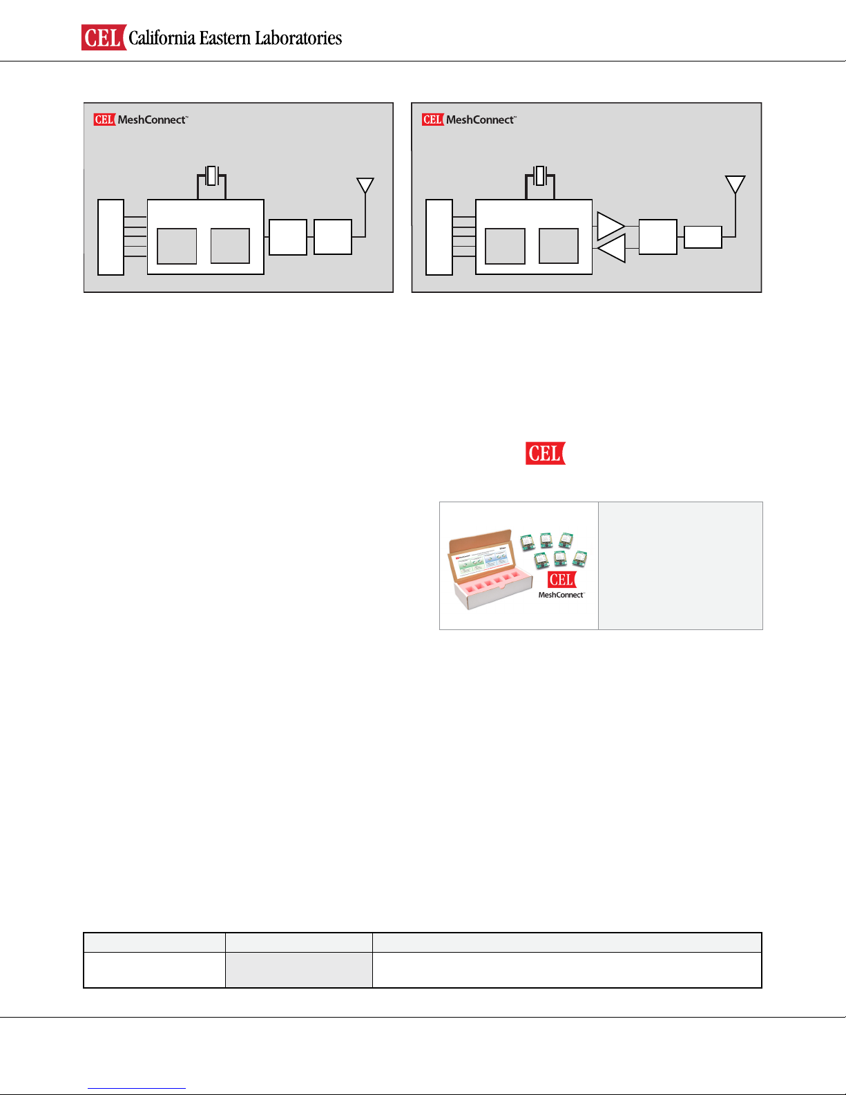
MODULE BLOCK DIAGRAMS
Radio
Micro
Balun
LPF
Castellation
Edge Connector
Ember EM357
24MHz
XTAL
Block Diagram
EM357 Mini Module (ZICM357SP0)
Radio
Micro
PA
LNA
LPF
TX/RX
Switch
Castellation
Edge Connector
Ember EM357
24MHz
XTAL
Block Diagram
EM357 Mini Module (ZICM357SP2)
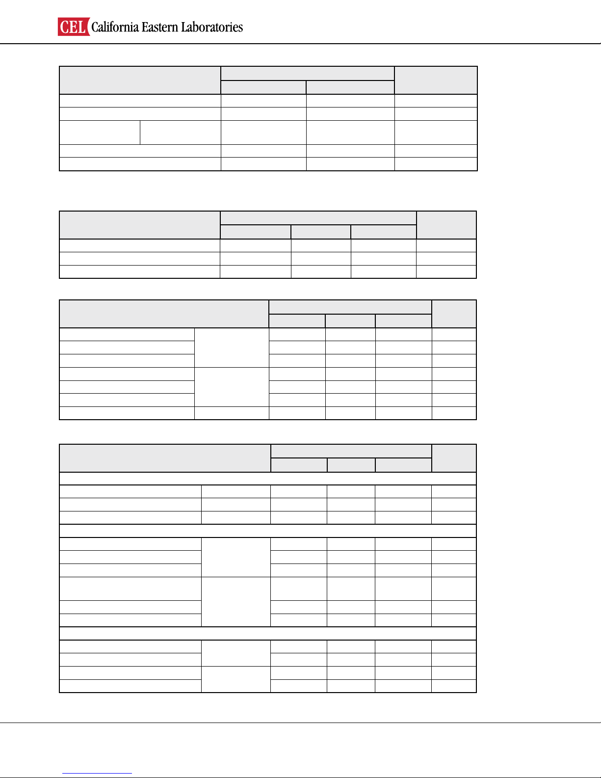
DEVELOPMENT KIT
CEL's Development Kit assist users in both evaluation and
development.
Ember Companion Kit:
CEL's MeshConnect EM35x Ember Companion Kit is
designed to work with the Ember development kit [EM35XDEV and EM35X-DEV-IAR]. Each module in this CEL kit is
soldered on a carrier board making it pin-for-pin compatible
with the Ember development board.
For more information regarding the MeshConnect
Development Kit, refer to the respective development
kit user guides documents. (Available at CEL’s website
www.cel.com/MeshConnect)
MeshConnect™ EM357 Mini Modules
™
MeshConnect
EM35x Ember Companion Kit
Kit Contents:
• ZICM357SP2-1 modules (2)
• ZICM357SP2-1C module (1)
• ZICM357SP0-1 modules (2)
• ZICM357SP0-1C module (1)
• Online Documentation
DEVELOPMENT KIT ORDERING INFORMATION
Part Number Order Number Description
MeshConnect™
EM35x Ember Companion Kit
ZICM-EM35X-DEV-KIT-2 MeshConnect EM35x Ember Companion Kit for Ember EM35x Dev Kits
Page 2

Introduction and Overview
Description..............................................................................................................................................................................................
1
Features
Applications
Ordering Information.............................................................................................................................................................................
1
Module Block Diagram...........................................................................................................................................................................
2
Development Kit
System Level Function
Transceiver IC
Antenna...................................................................................................................................................................................................
4
Power Amplier......................................................................................................................................................................................
4
Software/Firmware..................................................................................................................................................................................
4
Electrical Specication
Absolute Maximum Ratings...................................................................................................................................................................
4
Recommended (Operating Condition)..................................................................................................................................................
5
DC Characteristics
RF Characteristics
Pin Signal and Interfaces
Pin Signals I/O Conguration................................................................................................................................................................
6
I/O Pin Assignment
Module Dimensions
Module Footprint
Processing
Agency Certications
Shipment, Storage and Handling
Quality
Revision History
TABLE OF CONTENTS
.................................................................................................................................................................................................. 1
............................................................................................................................................................................................ 1
..................................................................................................................................................................................... 2
......................................................................................................................................................................................... 4
MeshConnect™ EM357 Mini Modules
.................................................................................................................................................................................. 5
.................................................................................................................................................................................. 5
................................................................................................................................................................................. 6
................................................................................................................................................................................ 8
.................................................................................................................................................................................... 9
.........................................................................................................................................................................................
...................................................................................................................................................................
.............................................................................................................................................
..................................................................................................................................................................................................
..............................................................................................................................................................................
10
11
14
14
15
Page 3

MeshConnect™ EM357 Mini Modules
TRANSCEIVER IC
CEL’s MeshConnect EM357 Mini Modules use the Ember EM357 transceiver IC. This IC incorporates the RF transceiver
with the baseband modem, a hardwired MAC, and an embedded ARM® Cortex™-M3 microcontroller, offering an excellent
low cost high performance solution for all IEEE 802.15.4 / ZigBee applications.
For more information about the Ember EM357 IC, visit www.ember.com
ANTENNA
CEL’s MeshConnect EM357 Mini Modules include an integrated Printed Circuit Board (PCB) trace antenna. An optional
conguration which uses a castellation pin on the module allows the user to connect an external antenna. The ZICM357SP0
has been certied with the PCB trace antenna only while the ZICM357SP2 has been certied with the PCB trace antenna and
a Nearson half-wave dipole antenna (part number: S181SA-2405S) on a 4 inch cable using the castellation pin of the module.
Please refer to the document "ZICM357SP2-1C External Antenna Implementation" for details describing the requirements that
must be followed to take advantage of the CEL certication. See Ordering Information on Page 1.
The PCB antenna employs a topology that is compact and highly efcient. To maximize range, an adequate ground plane
must be provided on the host PCB. Correctly positioned, the ground plane on the host PCB will contribute signicantly to the
antenna performance (it should not be directly under the module PCB Antenna). The position of the module on the host board
and overall design of the product enclosure contribute to antenna performance. Poor design affects radiation patterns and can
result in reection, diffraction and/or scattering of the transmitted signal.
For optimum antenna performance, the MeshConnect modules should be mounted with the PCB trace antenna overhanging the
edge of the host board. To further improve performance, a ground plane may be placed on the host board under the module, up
to the antenna (a minimum of 1.5" x 1.5" is recommended). The installation of an uninterrupted ground plane on a layer directly
beneath the module will also allow you to run traces under this layer. CEL can provide assistance with your PCB layout.
Here are some design guidelines to help ensure antenna performance:
• Never place the ground plane or route copper traces directly underneath the antenna portion of the module.
• Never place the antenna close to metallic objects.
• In the overall design, ensure that wiring and other components are not placed near the antenna.
• Do not place the antenna in a metallic or metalized plastic enclosure.
• Keep plastic enclosures 1cm or more from the antenna in any direction.
Under Industry Canada regulations, this radio transmitter may only operate using an antenna of a type and maximum (or
lesser) gain approved for the transmitter by Industry Canada. To reduce potential radio interference to other users, the antenna
type and its gain should be so chosen that the equivalent isotropically radiated power (e.i.r.p.) is not more than that necessary
for successful communication.
Conformément à la réglementation d'Industrie Canada, le présent émetteur radio peut fonctionner avec une antenne d'un type et
d'un gain maximal (ou inférieur) approuvé pour l'émetteur par Industrie Canada. Dans le but de réduire les risques de brouillage
radioélectrique à l'intention des autres utilisateurs, il faut choisir le type d'antenne et son gain de sorte que la puissance isotrope
rayonnée équivalente (p.i.r.e.) ne dépasse pas l'intensité nécessaire à l'établissement d'une communication satisfaisante.
POWER AMPLIFIER
CEL’s MeshConnect EM357 High Power Module (ZICM357SP2) includes a Power Amplier (PA). This PA delivers high
efciency, high gain, and high output power (Pout = +20.0 dBm TYP) to provide an extended range and reliable transmission
for fewer nodes in a network. For the ZICM357SP2, Power mode 2 with Power Setting "-2" is the maximum setting allowed for
FCC compliance. Operating in power mode 3 at higher power settings may damage the power amplier.
SOFTWARE/ FIRMWARE
CEL’s MeshConnect EM357 Mini Modules are ideal platforms for the EmberZNet PRO™, the industry’s most deployed and
eld proven ZigBee compliant stack supporting the ZigBee PRO feature Set. EmberZNET PRO is a complete ZigBee
protocol software package containing all the elements required for mesh networking applications. For more information
regarding the software development for this IC, visit www.ember.com
CEL provides reference software that runs multiple functions and executes various commands. The rmware allows the
execution of IEEE 802.15.4 communication, validation and manufacturing tests. For example, users can setup a simple
ZigBee Point-to-Point network to perform Range and Packet Error Rate (PER) tests. The software can also place the
module in various operating modes, which allows for setting and/or testing various parameters.
The ZICM357SP0 uses the transceiver's Primary RF ports for transmitting and should use power mode 1.
The ZICM357SP2 uses the transceiver's Alternate RF ports for transmitting and should use power mode 2.
Page 4
ABSOLUTE MAXIMUM RATINGS
MeshConnect™ EM357 Mini Modules
Description
Power Supply Voltage (V
Voltage on any I/O Line -0.3 V
RF Input Power
Storage Temperature Range -40 125 °C
Reow Soldering Temperature – 260 °C
Note: Exceeding the maximum ratings may cause permanent damage to the module or devices.
RECOMMENDED (OPERATING CONDITIONS)
Description
Power Supply Voltage (V
Input Frequency 2405 – 2480 MHz
Ambient Temperature Range -40 25 85 °C
DD) -0.3 3.6 VDC
ZICM357SP0
ZICM357SP2
DD) 2.1 3.3 3.6 VDC
MeshConnect™ ZICM357SPx Module
Min Max
DD + 0.3 VDC
–
–
MeshConnect™ ZICM357SPx Module
Min Typ Max
+15
+5
Unit
dBm
Unit
DC CHARACTERISTICS (@ 25⁰ C, VDD = 3.3V, ZICM357SP0 TX power mode 1, ZICM357SP2 TX power mode 2)
Description
Transmit Mode Current @ 8dBm
Transmit Mode Current @ 0dBm – 31 – mA
Receive Mode Current – 30 – mA
Transmit Mode Current @ 20dBm
Transmit Mode Current @ 0dBm – 58 – mA
Receive Mode Current – 34 – mA
Sleep Mode Current – 1 – µA
ZICM357SP0
ZICM357SP2
MeshConnect™ ZICM357SPx Module
Min Typ Max
– 44 – mA
– 150 – mA
Unit
RF CHARACTERISTICS (@ 25⁰ C, VDD = 3.3V, ZICM357SP0 TX power mode 1, ZICM357SP2 TX power mode 2)
Description
General Characteristics
RF Frequency Range 2405 – 2480 MHz
RF Channels 11 – 26 –
Frequency Error Tolerance -96.2 – 96.2 kHz
Transmitter
Maximum Output Power
Minimum Output Power – -40 – dBm
Offset Error Vector Magnitude – 5 35 %
Maximum Output Power
(using power mode 2, power setting -2)
Minimum Output Power – -40 – dBm
Offset Error Vector Magnitude – 5 35 %
Receiver
Sensitivity (1% PER, boost mode)
Saturation (maximum input level) 0 – – dBm
Sensitivity (1% PER, normal mode)
Saturation (maximum input level) -10 – – dBm
Note: For the ZICM357SP2, Power mode 2 with Power Setting "-2" is the maximum setting allowed for FCC compliance. Operating in power
mode 3 at higher power settings may damage the power amplier.
ZICM357SP0
ZICM357SP2
ZICM357SP0
ZICM357SP2
MeshConnect™ ZICM357SPx Module
Min Typ Max
– 8 – dBm
– 20 21 dBm
– -100 -94 dBm
– -103 -97 dBm
Unit
Page 5
 Loading...