

CEL JS02 User Manual
User
Manual
18V
POWERhandle
Jigsaw
JS02
POWERhandle Sold Separately
If you experience any problems with the product please contact
your supplier or nd your regional ofce via the website:
www.cel-global.com
No person should use this product without rst reading and
understanding all documentation and warning labels. Keep these
instructions safe and provide them to all users.
For use only as outlined in this document, any other use will be
considered as misuse.
© C Enterprise LTD 2013 Designed in UK Printed in China
Manual Version: 130624
www.cel-global.com • info@cel-global.com
UK • HK • USA • China • Europe • Australia • Japan
PRODUCT CODE
MOTOR TYPE/ RATED VOLTAGE
NO LOAD SPEED
TORQUE SETTINGS
CUTTING CAPACITY:
STEEL
WOOD
BLADE SHANK TYPE
WEIGHT WITH POWERHANDLE (PH12)
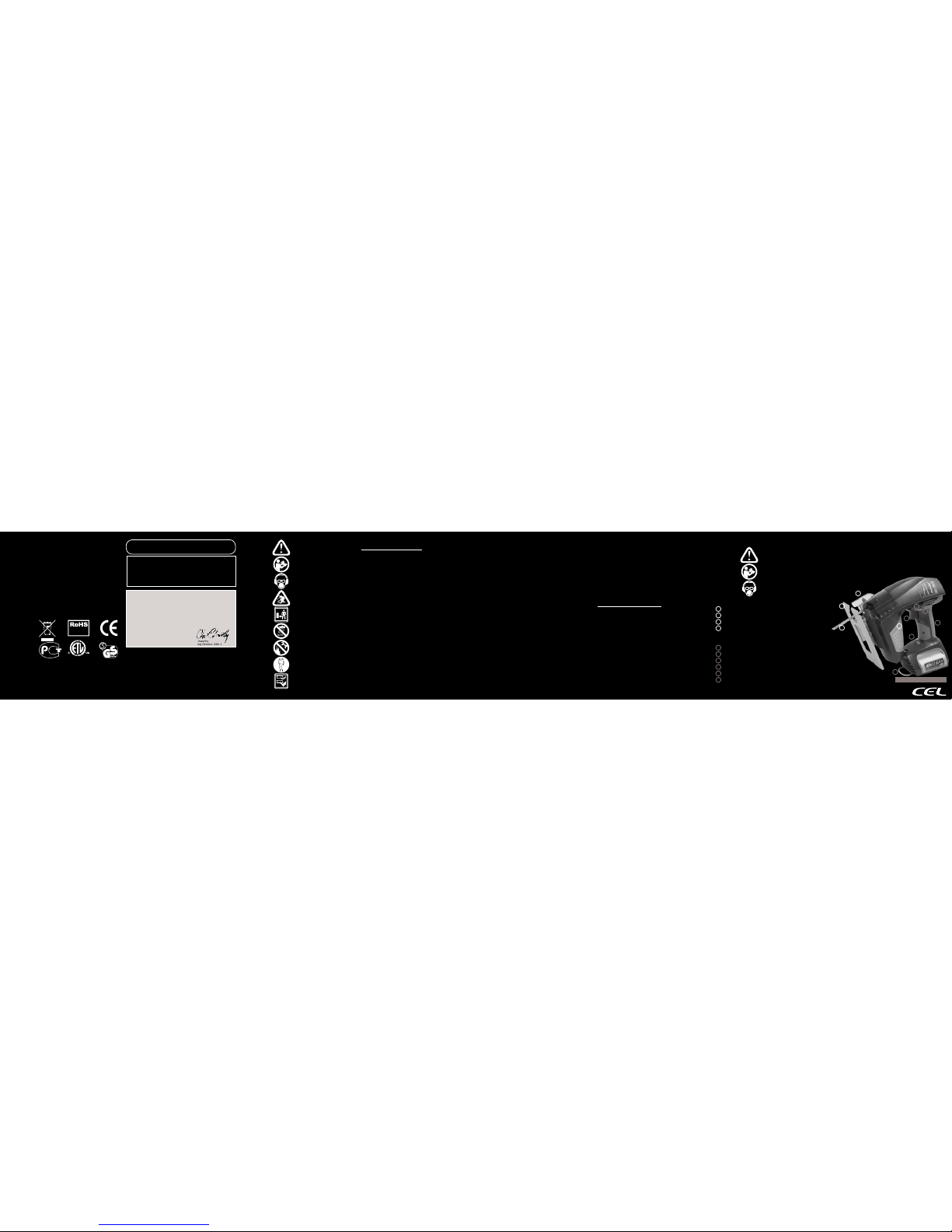
TECHNICAL SPECIFICATIONS GUARANTEE WARNING SYMBOLS IMPORTANT SAFETY NOTES
This product contains
materials that should
be recycled but can
not be disposed
of with regular
household waste.
For disposal options
contact your local
recycling centre,
council ofces
or your place of
purchase.
Guarantee
Normal wear and tear, including accessory wear, is not covered
under guarantee. Following successful registration, the product is
guaranteed for domestic use against manufacturing faults for a period
of 24 months. Proper care is required to maintain this product in
working condition. This product is not guaranteed for hire purposes.
If you have any questions, please contact us:
www.cel-global.com
Declaration of Conformity
We declare under our sole responsibility that the product described in
“Technical Specications” is in conformity with the following standards or
standardisation documents:
EN 60745-1:2006
EN 60745-2-11:2003+A11:07
Technical le can be provided by:
CEL-HK 1604 Nan Fung Commercial Centre, 19 Lam Lok Street,
Kowloon Bay, Hong Kong
C Enterprise (UK) LTD
Unit 4 Harbour Road Trading Estate
Portishead, BS20 7BL, UK
Chris Elsworthy
Managing Director- 24th June, 2013
WARNING! For AC tools and appliances; check that input voltages on
the rating plates and the plug types match your local mains supply. If it is
different contact your supplier immediately and follow their advice. Do not
modify the charger or plug in any way. For DC tools; only use batteries
supplied or manufacturer recommended replacements.
This product is sold in several congurations. The images and
descriptions in this user manual may differ from your product. For
features or accessories not covered by this manual or if you are unsure
about a feature or function contact your supplier or visit www.cel-global.
com where you can nd updated user manuals and compatible parts.
General Safety Rules for Power Tools
Read all warnings and all instructions.
Failure to follow the warnings and instructions may result in electric
shock, re and/or serious injury.
Save all warnings and instructions for future reference.
The term “power tool” in the warnings refers to your mains-operated
(corded) power tool or battery-operated (cordless) power tools plus
compatible chargers and accessories. POWERhandle refers to an
assembly containing a battery of cells, a trigger mechanism and other
controls. A POWERhandle contains no user serviceable parts.
1) Work area safety
a) Keep work area clean and well lit. Cluttered or dark areas invite
accidents.
b) Do not operate power tools in explosive atmospheres, such as in the
presence of ammable liquids, gases or dust. Power tools create sparks
which may ignite the dust or fumes.
c) Keep children and bystanders away while operating a power tool.
Distractions can cause you to lose control.
2) Electrical safety
a) Power tool plugs must match the outlet.
Never modify the plug in any way. Do not use any adapter plugs with
earthed (grounded) power tools. Unmodied plugs and matching outlets
will reduce risk of electric shock. Always fully uncoil cables to avoid heat
buildup.
b) Avoid body contact with earthed or grounded surfaces, such as pipes,
radiators, ranges and refrigerators. There is an increased risk of electric
shock if your body is earthed or grounded.
c) Do not expose power tools to rain or wet conditions. Water entering a
power tool will increase the risk of electric shock.
d) Do not abuse the cord. Never use the cord for carrying, pulling or
unplugging the power tool. Keep cord away from heat, oil, sharp edges
and moving parts.
Damaged or entangled cords increase the risk of electric shock.
e) When operating a power tool outdoors, use an extension cord suitable
for outdoor use. Use of a cord suitable for outdoor use reduces the risk of
electric shock. Fully uncoil all cords in use.
f) If operating a power tool in a damp location is unavoidable, use a
residual current device (RCD) protected supply. Use of an RCD reduces
the risk of electric shock.
3) Personal safety
a) Stay alert, watch what you are doing and use common sense when
operating a power tool. Do not use a power tool while you are tired
or under the inuence of drugs, alcohol or medication. A moment of
inattention while operating power tools may result in serious personal
injury.
b) Use personal protective equipment. Always wear eye protection.
Protective equipment such as dust mask, non-skid safety shoes, hard
hat, and/or hearing protection used for appropriate conditions will reduce
personal injuries. Be aware of dangerous conditions that can occur while
working on certain materials. Take appropriate measures to reduce
risk. For example; Oak and Beech can give off harmful dust. Use dust
extraction and respiratory protection along with other safety precautions.
c) Prevent unintentional starting. Ensure the switch is in the off-position
before connecting to power source and/or battery pack, picking up or
carrying the tool. Carrying power tools with your nger on the switch or
energising power tools that have the switch on invites accidents.
d) Remove any adjusting key or wrench before turning the power tool on.
A wrench or a key left attached to a rotating part of the power tool may
result in personal injury.
e) Do not overreach. Keep proper footing and balance at all times. This
enables better control of the power tool in unexpected situations.
f) Dress properly. Do not wear loose clothing or jewellery. Keep your hair,
clothing and gloves away from moving parts.
Loose clothes, jewellery or long hair can be caught in moving parts.
g) If devices are provided for the connection of dust extraction and
collection facilities, ensure these are connected and properly used. Use
of dust collection can reduce dust-related hazards.
4) Power tool use and care
a) Do not force the power tool. Use the correct power tool for your
application. The correct power tool will do the job better and safer at the
rate for which it was designed.
b) Do not use the power tool if the switch does not turn it on and off. Any
power tool that cannot be controlled with the switch is dangerous and
must be repaired.
c) Disconnect the plug from the power source and/or the battery
pack from the power tool before making any adjustments, changing
accessories, or storing power tools. Such preventive safety measures
reduce the risk of starting the power tool accidentally.
d) Store idle power tools out of the reach of children and do not allow
persons unfamiliar with the power tool or these instructions to operate
the power tool.
Power tools are dangerous in the hands of untrained users.
e) Maintain power tools. Check for misalignment or binding of moving
parts, breakage of parts and any other condition that may affect the
power tool’s operation.
If damaged, have the power tool repaired before use. Many accidents
are caused by poorly maintained power tools.
f) Keep cutting tools sharp and clean. Properly maintained cutting tools
with sharp cutting edges are less likely to bind and are easier to control.
g) Use the power tool, accessories and tool bits etc. in accordance with
these instructions, taking into account the working conditions and the
work to be performed. Use of the power tool for operations different from
those intended could result in a hazardous situation.
5) Battery tool use and care
a) Recharge only with the charger specied by the manufacturer. A
charger that is suitable for one type of battery pack may create a risk of
re when used with another battery pack.
b) Use power tools only with specically designated battery packs. Use
of any other battery packs may create a risk of injury and re.
c) When battery pack is not in use, keep it away from other metal objects,
like paper clips, coins, keys, nails, screws or other small metal objects,
that can make a connection from one terminal to another. Shorting the
battery terminals together may cause burns or a re.
d) Under abusive conditions, liquid may be ejected from the battery;
avoid contact. If contact accidentally occurs, ush with water. If liquid
contacts eyes, additionally seek medical help. Liquid ejected from the
battery may cause irritation or burns.
6) Service
Have your power tool serviced by a qualied and approved repair person
using only identical replacement parts. This will ensure that the safety of
the power tool is maintained.
Additional Safety Warnings for Jigsaws
• When operating the saw, use safety equipment including safety
goggles, ear protection, suitable dust mask and protective clothing
including safety gloves.
• Check the workpiece for any protruding nails, screw heads or anything
that could damage or obstruct the blade.
• Do not force the jigsaw, let the jigsaw do the work.
• Do not try and cut a curve that is too tight. This will put undue pressure
on the blade causing it to snap.
• Never use the saw near ammable liquids or gases.
• Allow the jigsaw to stop completely before removing it from the
workpiece.
• Keep hands away from cutting area and blade.
• Do not reach underneath the workpiece.
• If you are interrupted when operating the saw, complete the process
and switch off before looking up.
• Always hold the saw on parts that are insulated. If you accidentally cut
into hidden wiring or the saw’s own cable, the metal parts of the saw will
become “live”.
• Ensure the blade is held tightly by the quick release system but can run
freely in the blade guide. Adjust the blade guide as necessary for each
blade.
GENERAL
HAZARD
GENERAL
HAZARD
READ
INSTRUCTIONS
READ
INSTRUCTIONS
PROTECT VISION,
HEARING,
RESPIRATION
PROTECT VISION,
HEARING,
RESPIRATION
FLYING DEBRIS
BE AWARE OF
OTHERS
KEEP DRY
PROTECT FROM
OVERHEATING
WEAR
APPROPRIATE
CLOTHING
SHARP BLADES
3061583
JS02
#550 18V
0-2400 SPM
18+1+1
13mm (½”)
50mm (2”)
U or T
2kg
•
•
•
•
•
•
•
•
COMPLIANT
2011/95/EU
1
1
2
2
3
3
4
4
5
5
6
6
7
7
8
8
9
9
10
10
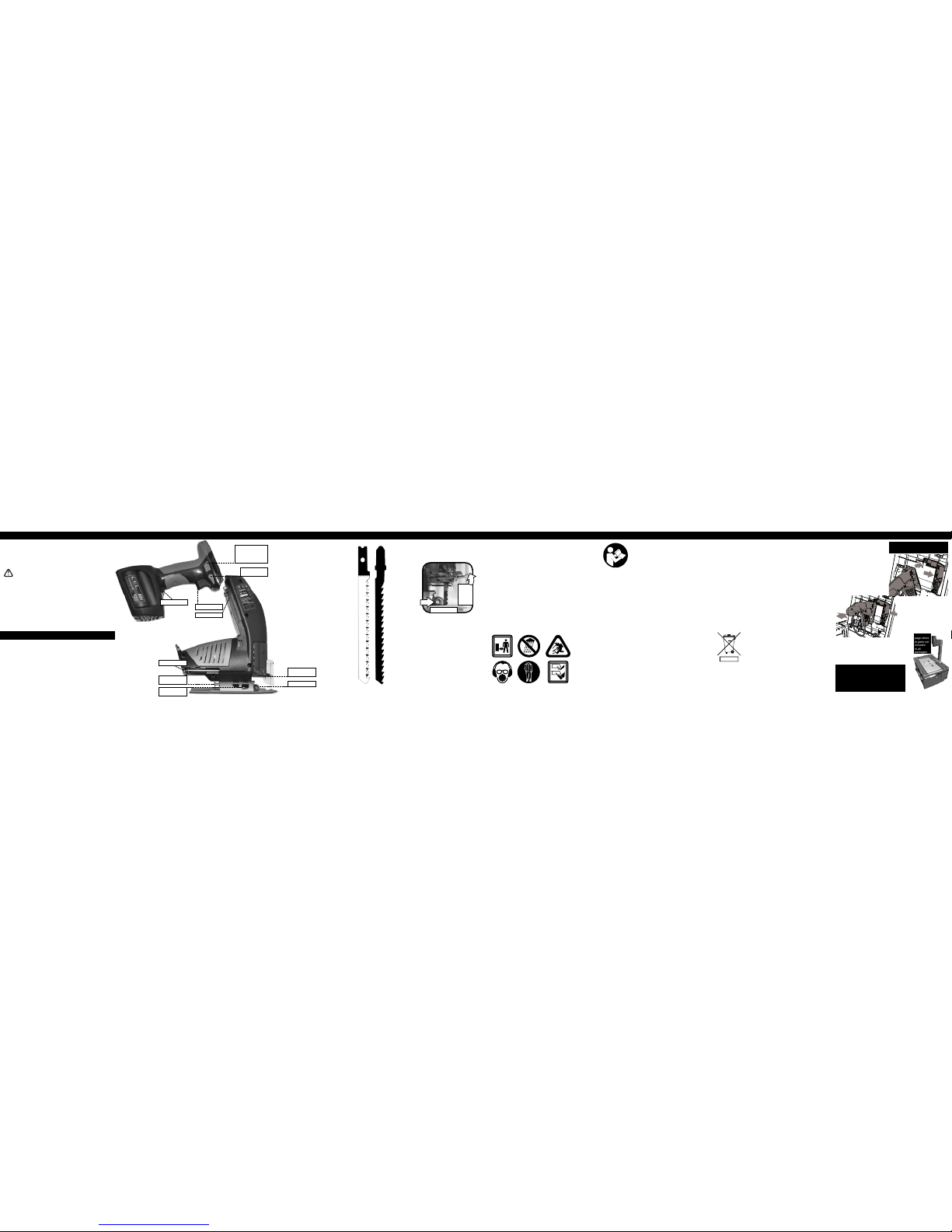
Quick Release Blade Holder
Adjustable Sole Plate
Blade (sold separately)
Motor Vents
POWERhandle (Sold Separately)
Direction Switch - Both Sides
POWERhandle Release Slider - Both Sides
Trigger
Soft Insulated Grip
Worklight
Belt Loop
NOTE! This
page refers
to parts not
included
in all
packages.
Fit the Jig Saw to the Case Lid
Open the case lid and remove any
tted tools.
Slide the Locking Slider out of the
way. Fit the rear of the Sole Plate
into the recess at the bottom of
the opening in the case lid and the
blade through the small slot in the
case lid. Rotate the saw into place
and release the Locking Slider,
ensure it slides back to hold the
saw in place securely.
Fit the Internal Power Coupling
onto the Rails on the saw in
where the POWERhandle
connects for handheld use.
Set Blade Angle then close and
latch the lid.
Insert the Post/Fence vertically
into the rear of the case with
the small
hook
toward the rear of the case. Push it down until it
locks into place, to adjust the height or remove the
post you can lift the Locking Lever. Fit the Work
Clamp into a pair of holes on the Post and tighten
down onto your workpiece.
NOTE! Before using briey activate the jigsaw to ensure the blade is
centred and secure. If there is any binding or unusual movement then
loosen and re-t.
To start the Jigsaw
Press the Safety Switch from either side and hold while pressing the
Variable Trigger. The safety switch can be released once the jigsaw is
running.
NOTE! Always secure your work in a way that allows the blade to move
freely below the cut material and so that the work piece does not jam the
blade between cut edges.
NOTE! Firm pressure keeping the sole plate on the work piece will
prevent the jigsaw from kicking back if the teeth on the blade suddenly
catches in the work piece.
WARNING! Take extra care to prevent ngers and other objects coming
into contact with the blade, especially on the other side of materials being
cut.
ALWAYS WEAR SAFETY EQUIPMENT WHEN OPERATING POWER
TOOLS
FITTING A POWERhandle
FITTING A POWERhandle
INTENDED USE FITTING/REMOVING A BLADE OPERATING THE TOOL CARE AND ENVIRONMENTOPERATION TIPSCHOOSE THE CORRECT TOOL
To Fit a jigsaw blade
•Select a sharp high quality blade suitable for your
work.
•Remove the POWERhandle to prevent accidental
starting.
•Using the Hex Key
loosen the Sole
Plate Locking Screw
and Blade Guide
Adjuster.
•Support the body of
the jigsaw and lift the
Blade Release Lever
as shown.
•Remove the
previous blade and
ensure there is no
debris which will jam the mechanism.
•Insert a new blade with the teeth facing the front of
the jigsaw and push rmly all the way into the Blade
Clamp.
•Release the lever and ensure it has locked the blade
into position. There should be no play in blade or
lever.
•Position the Blade Guide so the roller guides the
blade square to the Blade Clamp.
•Adjust the Sole Plate to a suitable angle, ensure the
teeth on the Sole Plate are pushed forward and have
locked in place.
•Tighten the Blade Guide Adjuster by hand.
Note, the Blade Guide should be able to turn freely
while preventing sideways blade movement.
•Lock the Sole Plate and Blade Guide Roller in place
with the Sole Plate Locking Screw.
Compatible Jigsaw blades
U (Universal Type) or T (T shank Type, or
Standard Bayonet) as shown on the right.
Choosing the right blade
TPI means Teeth Per Inch, also know as TOOTH
SPACING measured tip to tip. KERF is the
width of the cut. DRAFT indicates the blade is
thicker at the teeth edge than the back edge,
this helps to prevent jamming and allows the
blade to cut curves but will also make it harder
to cut a straight line. Blades described as THIN
indicate the distance from teeth edge to back
edge, a THICK blade will assist in a straight cut.
Tooth patterns: MILLED, longer lasting, good for
general use and hard woods, give a rougher cut
than; GROUND, sharper teeth that wear quickly
but give a clean nish and a faster cut; GROUND
TAPERED and GROUND SIDE give good
and excellent curve capabilities respectively;
REVERSE CUT, cut on the down stroke. These
reverse cut blades are ideal for laminated
surfaces such as kitchen work surfaces but make
the jigsaw much harder to control as they push
the sole plate away from the work piece.
•Measure and mark cuts allowing for the width of
the cut, KERF.
•Let the saw reach full speed before allowing
blade to contact work piece.
•Choose a sharp good quality blade that is
suitable for your material and type of cut, see
below.
•Keep sandpaper handy to nish cut surfaces.
•To reduce kickback make sure your blade is
long enough so that even at the top of the up stroke it is visible on the
other side of the material.
•Clamp your work so it cannot be moved by the stroke of the jigsaw, this
will make it safer and your cut will be cleaner and more efcient.
•Check both sides of the cut, blades can ex in the material and go off
line easily. Also check for objects in the path of the blade.
•Wood
For fast straight cuts with a rough nish use a THICK blade with large
~3mm~ TOOTH SPACING (~10TPI).
For a smooth nish use a blade with more teeth (20-30TPI)
•Metal
Soft metals can sometimes be cut with a wood blade.
Harder metals and pipes can require a specialized blade. Usually over
20TPI, with a MILLED WAVY tooth pattern for a good nish and long life.
Heat buildup may harden some metals, use oil or water to keep cool.
•Plastic, Perspex, Plexiglass
Cover the sole plate with masking tape or similar to prevent scratching.
Support with a plywood or similar to prevent sagging. Cover the cut
area with masking tape to prevent splitting and aid in marking up. Use
a GROUND tooth blade ~24TPI keep pressure and speed constant to
prevent melting, pausing with the motor running will cause heat buildup.
Use water to keep the blade and the material cool.
NOTE! Remove any debris from the area that joins the POWERhandle to
the tool. Damage to contacts or mechanical controls could occur if debris
is caught between them.
Align the rails on the tool so they will slide smoothly into the rails on the
POWERhandle. Once aligned, slide the two parts together rmly until
there is a “click” as the locking catch engages. Test the catch is secure
and the electrical contacts are engaged by selecting a direction and
briey pressing the trigger.
Removing the POWERhandle
Hold down the POWERhandle Lock Button while sliding the two
POWERhandle Release Switches to the rear of the handle and slide the
POWERhandle out of the tool from the rear.
NOTE! These pages refer to the PH12 POWERhandle (sold separately).
If your POWERhandle is different please refer to the relevant instructions for that model.
With an appropriate attachment tted in the chuck this tool is intended for
cutting wood, metal and plastic in straight lines or curves up to the ability
of the tted attachment and within the specication of the tool.
Sharp blades, heat buildup, harmful dust and ying debris are a
danger to user and bystanders. Use of suitable protective clothing,
gloves, footwear, lung, eye and ear protection as well as safe working
practices can reduce these risks. Always switch the tool off prior to any
adjustment.
Read and understand all safety warnings and all instructions before
operating this product.
Failure to follow the warnings and instructions may result in electric
shock, re and/or serious injury.
WARNING! When changing battery, bit or whenever the tool is not in
immediate use the direction switch must be in its central locked position to
prevent accidental starting. Ensure the tool will not be accidentally started
by pressing the trigger.
4mm Hex Key
Variable Trigger
Rails
Work Light
Safety Switch
(both Sides)
Release Catch
(both sides or
on rear of some
POWERhandles)
Blade Guide
Sole Plate
Locking Screw
Quick Release
Blade Clamp
Blade Guide
Adjuster
Blade Guide
Quick
Release
Blade
Clamp
Lever
U T
General inspection
Regularly check that all the xing screws are present and tight, they may
vibrate loose over time.
Keep the tool’s air vents unclogged and clean at all times.
Remove dust and dirt regularly.
Cleaning is best done with compressed air or a rag.
CAUTION, Do not use cleaning agents to clean the plastic parts of the
tool. A mild detergent on a damp cloth is recommended. Water must
never come into contact with the tool.
After each use, carefully clean the tool with a brush or rag.
Clear any debris from around the battery mount, moving parts and clips.
Lubrication
No internal lubrication is necessary, the bearing area is sealed.
A coating of machine oil on the metal parts will help prevent corrosion.
Storage
Store the tool, instruction manual and accessories in a secure, dry place.
In this way you will always have all the information and parts ready
to hand. Lithium ion batteries should ideally be stored with 40 to 80%
capacity between 10ºC and 20ºC (50ºF and 68ºF).
WARNING! Always charge Li-ion batteries before storage and at least
every 3 months to prevent permanent damage.
Environment
When the time comes to dispose of this product please
consider the environment and take it to a recognised
recycling facility instead of disposing with general
household waste.
Call your local council, civic amenity site, or recycling
centre for information on the recycling and disposal of
electrical products and batteries. If you do not have
access to suitable disposal facilities in your area please contact your
place of purchase, they will advise you on the best way to dispose of your
product.
Maintenance
All electrical parts should be regularly serviced by an approved engineer.
READ ALL
INSTRUCTIONS
ASSEMBLE A SCROLL SAW
These instructions should be read in
conjunction with those for the case
used.
START / STOP
Fit a POWERhandle into the Main Dock on
the case. Use the Green and Red Start / Stop
buttons to start and stop the tools tted to the
case. The backlight on the LCD Display will
glow green when the Start button is pressed.
 Loading...